Language selection

Search

Patent 2021168 Summary

Third-party information liability

Some of the information on this Web page has been provided by external sources. The Government of Canada is not responsible for the accuracy, reliability or currency of the information supplied by external sources. Users wishing to rely upon this information should consult directly with the source of the information. Content provided by external sources is not subject to official languages, privacy and accessibility requirements.

Claims and Abstract availability

Any discrepancies in the text and image of the Claims and Abstract are due to differing posting times. Text of the Claims and Abstract are posted:

  • At the time the application is open to public inspection;
  • At the time of issue of the patent (grant).
(12) Patent: (11) CA 2021168
(54) English Title: FASCIA ANGLE ADAPTER FOR AN EAVESTROUGH SYSTEM
(54) French Title: CORNIERE DE BORDURE DE TOIT POUR SYSTEMES DE GOUTTIERES
Status: Term Expired - Post Grant Beyond Limit
Bibliographic Data
(51) International Patent Classification (IPC):
  • E04D 13/04 (2006.01)
(72) Inventors :
  • BRANT, ANTHONY W. (Canada)
(73) Owners :
  • GSW INC.
  • EURAMAX CANADA, INC.
(71) Applicants :
  • GSW INC. (Canada)
  • EURAMAX CANADA, INC. (Canada)
(74) Agent: DENNISON ASSOCIATES
(74) Associate agent:
(45) Issued: 2002-02-12
(22) Filed Date: 1990-07-13
(41) Open to Public Inspection: 1992-01-14
Examination requested: 1997-06-19
Availability of licence: N/A
Dedicated to the Public: N/A
(25) Language of filing: English

Patent Cooperation Treaty (PCT): No

(30) Application Priority Data: None

Abstracts

English Abstract


The present invention relates to a fascia angle
adapter for an eavestroughing system wherein the fascia
angle adapter allows for supporting of an eavestrough
hanger or other support fitting at different angles
relative to a fascia board. The adapter is placed
intermediate the hanger and the fascia board. The adapter
has a base member having a fascia engaging surface, a top
port for securing of the adapter to a fascia board, and an
eccentric cam supported by the base member and movable with
respect thereto whereby the cam can be moved to various
positions such that the exterior surface of the cam is
spaced a different distance from the fascia engaging
surface. The cam member is preferably rotatably supported
within the base member and has a number of planar surfaces
about the periphery of the cam for defining, in cooperation
with the base member, predetermined angles for known angled
fascia. This arrangement provides a simple solution
whereby the installer can easily adjust the angle of the
eavestrough hook for optimum utility.


Claims

Note: Claims are shown in the official language in which they were submitted.

-5-
THE EMBODIMENTS OF THE INVENTION IN WHICH AN EXCLUSIVE
PROPERTY OR PRIVILEGE IS CLAIMED ARE DEFINED AS FOLLOWS:
1. A fascia angle adapter for an eavestrough
system comprising a base member having a fascia engaging
surface and a second. surface opposite said fascia
engaging surface adapted to support a mounting base of an
eavestrough hanger, said fascia engaging surface and said
second surface being angled to define a shallow wedge,
said adapter further including an eccentric cam rotatably
supported by said base member and projecting forwardly of
said second surface, said cam being rotatable within said
base member to define different eavestrough hanger
support positions.
2. A fascia angle adapter for an eavestrough
system comprising a base member having a fascia engaging
surface, a top port for securing of said adapter to a
fascia board, and an. eccentric cam supported by said base
member and movable with respect thereto whereby the cam
can be moved to various positions such that the exterior
surface of said cam is spaced a different distance from
said fascia engaging surface.
3. A fascia angle adapter as claimed in claim 2
wherein said cam has at least three planar surfaces about
the periphery of said cam for defining in cooperation
with said base member predetermined angles for known
angled fascia.
4. A fascia angle adapter as claimed in claim 2
wherein said cam has pans either side thereof which are
received in support arms of said base whereby said cam is
rotatable within said base.
5. A fascia angle adapter as claimed in claim 4
wherein said base has two side sections interconnected at

-6-
the top thereof by a bridging member having therein said
top port for securing of said adapter to a fascia board,
said side sections being interconnected at the bottom
thereof by a bottom member.
6. A fascia angle adapter as claimed in claim 4
wherein said base member is generally closed on the sides
and closed on the top and bottom to define a framework
having a wedge-like shape, said framework further
including an intermediate reinforcing strut extending
between said side sections.
7. A fascia angle adapter as claimed in claim 6
wherein said cam is located below the center plane of
said framework.
8. A fascia angle adapter as claimed in claim 7
wherein said support arms of said base are located on
said side sections and each arm includes a bifurcated
section for retaining of said pins of said cam.
9. A fascia angle adapter as claimed in claim 8
wherein each cam has at least three separate lobes each
of which is a planar face for supporting a eavestrough
hook.
10. A fascia angle adapter as claimed in claim 9
wherein said each planar face of said cam is a different
perpendicular distance from said pins which in
cooperation with said base define a different angle for
supporting of an eavestrough hook necessary for different
roof slopes where the fascia is perpendicular to the
slope of the roof.
11. A fascia angle adapter as claimed in claim 10
wherein said cam has three lobes and is generally
triangular.

-7-
12. A fascia angle adapter as claimed in claim 11
wherein said reinforcing strut has a front surface for
engaging an eavestrough fitting when properly received
within said adapter.
13. In combination an eavestrough fitting and a
fascia angle adapter, said fascia angle adapter and said
eavestrough fitting each having a similar mounting port
for receiving a common fastening member, said fascia
angle adapter including a displaceable member at a
forward edge thereof which cooperates with said adapter
adjacent said mounting port to control the angle of said
eavestrough fitting relative to said adapter when aligned
therewith in an operative position and said mounting
ports are aligned, said displaceable member being movable
to various positions altering the spacing between said
eavestrough fitting and said adapter whereby the angle of
said eavestrough fitting and said adapter whereby the
angle of said eavestrough fitting relative to said
adapter is varied.
14. In combination as claimed in claim 13 wherein
said displaceable member is removable from said adapter
whereby said adapter and eavestrough fitting define a
further angle of said eavestrough fitting relative to
said adapter.
15. In combination as claimed in claim 14 wherein
said displaceable member is a cam having different faces
thereon for appropriately positioning said eavestrough
fitting.
16. In combination as claimed in claim 15 wherein
said cam is rotatably supported by said adapter.

-8-
17. In combination as claimed in claim 16 wherein
said adapter has a base, said base comprising two side
portions interconnected at the top thereof by a bridging
member having therein a top port for securing of said
adapter to a fascia board, said side portions being
interconnected at the bottom thereof by a bottom member.
18. In combination as claimed in claim 17 wherein
said base member is generally closed on the sides and
closed on the top and bottom to define a framework having
a wedge-like shape, said framework further including an
intermediate reinforcing strut extending between said
side sections.
19. In combination as claimed in claim 18 wherein
said cam has at least three separate lobes each of which
is a planar face for supporting a eavestrough hook.
20. In combination as claimed in claim 19 wherein
said cam lobes accommodate roof slopes 4/12, 5/12, and
6/12 where the fascia board is generally perpendicular to
said roof.

Description

Note: Descriptions are shown in the official language in which they were submitted.


WH-8091-90 - 1 -
TITLE' FASCIA ANGLE ADAPTER FOR AN EAVESTROLTGH SYSTEM
FIELD OF THE INVENTION
The present invention relates to a fascia angle
adapter for an eavestrough system. In particular, the
invention relates to a fascia angle adapter having a
movable member which can be adjusted to various positions
to appropriately position an eavestrough hanger.
BACKGROUND OF THE INVENTION
In the installation of. an eavestrough system, it is
important that the eavestrough be secured in a manner such
that it is generally horizontal, whereby the full capacity
of the eavestrough can be realized. In some home
construction, the fascia board is mounted perpendicular to
the slope of the roof. and thus, the angle of the slope of
the roof must be corrected when eavestrough hangers are
mounted to the fascia board. Spacers have been used in the
past for appropriately spacing the eavestrough hanger from
the fascia board and other more complicated ratchet type
arrangements have been used for securing of the eavestrough
hook at the appropriate angle from the fascia board.
There remains a need to provide a simple mechanism
which can easily be mounted and cooperates with the
eavestrough hanger for ease of installation while
accommodating various angled fascia boards.
SLTMMARY OF THE I1VVENTION
A fascia angle adapter, according to the present
invention, comprises a base member having a fascia engaging
surface, a top port for securing of the adapter to the
fascia board, and an eccentric cam supported by said base
member and movable with respect thereto whereby the cam can
be moved to various positions, such that the exterior
surface of the cam is movable to various positions varying
the distance between the exterior surface of the cam and
the fascia engaging surface. This structure allows an

~6~~~68
WH-8041-90 - 2 -
eavestrough hanger to be supported by the fascia angle
adapter at various positions by merely adjusting of the cam
member to the appropriate position. Thus, the one adapter
is suitable for roof slopes of different angles, allowing
ease of stock keeping and ease of use by the end user.
BRIEF DESCRIPTION OF THE DRAWINGS
Preferred embodiments of the invention are shown in
the drawings, wherein:
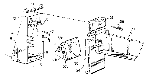
Figure 1 is an exploded perspective view of the
fascia angle adapter and an associated eavestrough hanger;
Figure 2 is a side elevation of the fascia angle
adapter and hanger mounted on an angled fascia board;
Figure 3 is a perspective view of the fascia angle
adapter;
Figure 4 is a side elevation of the base member of
the fascia angle adapter; and
Figures 5 through 7 are side elevations showing the
fascia angle adapter on angled fascia boards associated
with predetermined roof slopes.
DETAILED DESCRIPTION OF THE PREFERRED EMBODIMENTS
The fascia angle adapter 2 shown in Figure 1 is
designed far supporting the eavestrough hanger 50 at
predetermined angles. The fascia angle adapter is for use
where the fascia board is not vertical, but is
perpendicular to the roof slope or at some other angle
relative to the roof slope requiring correction. In order
to satisfactorily install the eavestrough system, the
eavestrough should be generally horizontal and thus, a
correction must be made for proper positioning of the
eavestrough hanger. The fascia angle adapter 2 has a base
member 4 with a fascia engaging surface 6. The base 4 also
includes a second surface collectively defined by the
surfaces identified as 8 in Figure 1 for supporting of a
mounting base, if required. This would be the case where
the eccentric cam, generally shown as 30, is not used and

2fl211~~
WH-8041-90 - 3 -
the support member of the eavestrough hanger is braced by
second surface 8. When the eccentric cam is inserted in
the base member 4, the eavestrough hanger 50 is supported
adjacent the top mount port 18 and by one of the planar
surfaces 32a through 32c of the eccentric cam shown in
Figure 1. The particular planar surface that is used will
depend upon the angular position of the eccentric cam 30.
The base member 4 has side sections 9 which include
bifurcated arms 10 for engaging the cam pins 34 provided
either side of the eccentric cam 30. The base member 4
also includes a bridging member 12 provided adjacent the
top of the base member 4, an intermediate strut 16
extending horizontally between the side sections ~, and a
bottom member 14 essentially defining a rectangular like
framework. The base member 4 has an overall wedge type
shape, as the support surface 8 and the fascia engaging
surface 6 are angled to define such a wedge configuration.
The rear and front of the base member are generally open.
The eccentric cam 30, in this case, is of a three
lobe type configuration and the surfaces of the lobe 32a
through 32c are spaced different perpendicular distances
from the cam pins 34.
To assist the end user in accurately positioning of
the eavestrough hanger 50 or other support fitting, the cam
pins on the flat surface thereof can include a recess, in
this case in the form of a cross, to allow adjustment by
means of a Phillips screwdriver.
The fascia angle adapter is shown mounted on a
fascia board in Figure 2 and is supporting the eavestrough
hanger 50. As can be seen, the mounting port 52 of the
eavestrough hanger and the top mounting port 18 of the
fascia angle adapter are aligned and a common screw 58 is
used for securing of the two components to the fascia
board. The cam member has been appropriately adjusted such
that the eavestrough hanger 50 extends generally
horizontally, as measured by the cantilevered arm 56 such

~fl2~~~~
WH-8041-90 - 4 -
that the eavestrough is generally horizontal. Thus, the
full capacity of the eavestrough can be realized.
Figures 5 through 6 show various positions of the
cam supporting the eavestrough hanger for different roof
slopes. There are basically four common roof slopes and
the fascia angle adapter has been configured such that
without the cam, the shallowest slope, a 3/12, is satisfied ,
and the cam and base member accommodate the other three
angles, namely, a 4/12, a 5/12 and a 6/12.
As can be seen from the above, the fascia angle
adapter provides a simple solution for satisfying the
common corrections required for roof slopes of 3/12, 4/12,
5/12 and 6/l2.where the fascia board is generally
perpendicular thereto. It can further be appreciated that,
if necessary, other cam members can be provided or the cam
member can be modified to have additional faces to position
the eavestrough hanger 50 or other support fitting at
different angles.
The cam 50 is basically forced into the bearings
provided at the base of the bifurcated arms 10 and is
maintained therein by means of a generally tight fit with
the cam pins. The cam does not move from the desired
position, as it is engaging the flat surface of the support
member 54 of the eavestrough hanger or other eavestrough
support fitting and the gravity exerted on the hanger, due
to its own weight and the weight of the eavestrough,
maintains the cam in this adjusted position. Eavestrough
hangers are the most commonly used fittings used to support
the eavestrough, however the fascia angle adapter is used
in combination with joiners and other fittings adapted to
provide a support connection with the fascia.
Although various preferred embodiments of the
present invention have been described herein in detail, it
will be appreciated by those skilled in the art, that
variations may be made thereto without departing from the
spirit of the invention or the scope of the appended
claims.

Representative Drawing
A single figure which represents the drawing illustrating the invention.
Administrative Status

2024-08-01:As part of the Next Generation Patents (NGP) transition, the Canadian Patents Database (CPD) now contains a more detailed Event History, which replicates the Event Log of our new back-office solution.

Please note that "Inactive:" events refers to events no longer in use in our new back-office solution.

For a clearer understanding of the status of the application/patent presented on this page, the site Disclaimer , as well as the definitions for Patent , Event History , Maintenance Fee  and Payment History  should be consulted.

Event History

Description Date
Inactive: Expired (new Act pat) 2010-07-13
Letter Sent 2009-05-28
Letter Sent 2007-10-26
Inactive: Office letter 2007-04-26
Inactive: Office letter 2007-04-13
Letter Sent 2006-09-22
Grant by Issuance 2002-02-12
Inactive: Cover page published 2002-02-11
Pre-grant 2001-11-13
Inactive: Final fee received 2001-11-13
Letter Sent 2001-05-11
Notice of Allowance is Issued 2001-05-11
Inactive: Approved for allowance (AFA) 2001-05-01
Amendment Received - Voluntary Amendment 2001-04-04
Inactive: S.30(2) Rules - Examiner requisition 2000-10-06
Letter Sent 1997-08-15
Inactive: Application prosecuted on TS as of Log entry date 1997-08-14
Inactive: Status info is complete as of Log entry date 1997-08-14
All Requirements for Examination Determined Compliant 1997-06-19
Request for Examination Requirements Determined Compliant 1997-06-19
Application Published (Open to Public Inspection) 1992-01-14

Abandonment History

There is no abandonment history.

Maintenance Fee

The last payment was received on 2001-07-13

Note : If the full payment has not been received on or before the date indicated, a further fee may be required which may be one of the following

  • the reinstatement fee;
  • the late payment fee; or
  • additional fee to reverse deemed expiry.

Patent fees are adjusted on the 1st of January every year. The amounts above are the current amounts if received by December 31 of the current year.
Please refer to the CIPO Patent Fees web page to see all current fee amounts.

Owners on Record

Note: Records showing the ownership history in alphabetical order.

Current Owners on Record
GSW INC.
EURAMAX CANADA, INC.
Past Owners on Record
ANTHONY W. BRANT
Past Owners that do not appear in the "Owners on Record" listing will appear in other documentation within the application.
Documents

To view selected files, please enter reCAPTCHA code :


To view images, click a link in the Document Description column. To download the documents, select one or more checkboxes in the first column and then click the "Download Selected in PDF format (Zip Archive)" or the "Download Selected as Single PDF" button.

List of published and non-published patent-specific documents on the CPD .

If you have any difficulty accessing content, you can call the Client Service Centre at 1-866-997-1936 or send them an e-mail at CIPO Client Service Centre.


Document
Description 
Date
(yyyy-mm-dd) 
Number of pages   Size of Image (KB) 
Claims 2001-04-03 4 152
Drawings 1994-03-31 4 91
Abstract 1994-03-31 1 23
Claims 1994-03-31 4 118
Description 1994-03-31 4 160
Representative drawing 1999-04-18 1 20
Representative drawing 2002-01-07 1 20
Acknowledgement of Request for Examination 1997-08-14 1 178
Commissioner's Notice - Application Found Allowable 2001-05-10 1 163
Correspondence 2001-11-12 1 38
Correspondence 2006-10-26 17 697
Correspondence 2007-04-12 1 15
Correspondence 2007-04-25 1 15
Fees 1996-05-22 1 38
Fees 1995-05-23 1 39
Fees 1994-05-01 1 40
Fees 1993-06-07 1 35
Fees 1992-07-08 1 29