Language selection

Search

Patent 2021205 Summary

Third-party information liability

Some of the information on this Web page has been provided by external sources. The Government of Canada is not responsible for the accuracy, reliability or currency of the information supplied by external sources. Users wishing to rely upon this information should consult directly with the source of the information. Content provided by external sources is not subject to official languages, privacy and accessibility requirements.

Claims and Abstract availability

Any discrepancies in the text and image of the Claims and Abstract are due to differing posting times. Text of the Claims and Abstract are posted:

  • At the time the application is open to public inspection;
  • At the time of issue of the patent (grant).
(12) Patent Application: (11) CA 2021205
(54) English Title: ANTI-THEFT STEERING COLUMN CUFF DEVICE FOR AUTOMOBILES AND THE LIKE
(54) French Title: SECURITE ANTI-VOL POUR COLONNE DE DIRECTION DE VEHICULE AUTOMOBILE OU POUR AUTRES ELEMENTS SEMBLABLES
Status: Deemed Abandoned and Beyond the Period of Reinstatement - Pending Response to Notice of Disregarded Communication
Bibliographic Data
(51) International Patent Classification (IPC):
  • B60R 25/023 (2013.01)
  • B60R 25/01 (2013.01)
  • E05B 13/00 (2006.01)
  • E05B 73/00 (2006.01)
(72) Inventors :
  • EREMITA, NUNZIO (United States of America)
  • EREMITA, NUNZIO (United States of America)
(73) Owners :
  • NUNZIO EREMITA
  • NUNZIO EREMITA
(71) Applicants :
(74) Agent:
(74) Associate agent:
(45) Issued:
(22) Filed Date: 1990-07-16
(41) Open to Public Inspection: 1992-01-17
Examination requested: 1991-12-13
Availability of licence: N/A
Dedicated to the Public: N/A
(25) Language of filing: English

Patent Cooperation Treaty (PCT): No

(30) Application Priority Data: None

Abstracts

English Abstract


ABSTRACT OF THE DISCLOSURE
An anti-theft steering column cuff device for
automobiles and the like is provided and consists of two box
shaped casing which are removable connected and locked to the
steering column in which one of the casings covers and
protects an ignition switch to prevent an unauthorized person
from operating the ignition switch.
-9-


Claims

Note: Claims are shown in the official language in which they were submitted.

CLAIMS
What is claimed is:
1. An anti-theft cuff device for a motor vehicle having
a steering wheel and a steering column with an ignition
switch, said device comprising:
a) a first box shaped casing having an open side to fit
against one side of a steering column;
b) a second box shaped casing having a curved open side
to fit against opposite side of the steering column so as to
cover and protect the ignition switch;
c) a hasp member extending between said first box shaped
casing and said second box shaped casing so as to removably
connect said first box shaped casing to said second box shaped
casing on the steering column; and
d) means extending between said first box shaped casing
and said second box shaped casing opposite said hasp member,
for locking said cuff device to the steering column to prevent
an unauthorized person from operating the ignition switch.
2. An anti-theft cuff device as recited in Claim 1,
wherein said first box shaped casing includes a base wall,
opposite said open side thereof, having two openings
therethrough, so that a tilt lever on the steering column can
extend through one of said openings while a signal lever on
the steering column can extend through other of said openings.
-7-

3. An anti-theft cuff device as recited in Claim 2,
wherein said hasp member includes:
a) a curved plate having a hooked projection thereon,
said curved plate being attached to and extending away from an
end wall at said open side of said first box shaped casing;
and
b) a curved strap having a slot therethrough and hinged
to an end wall at said open side of said second box shaped
casing so that said slot can fit over said hooked projection
to be removable connected thereto.
4. An anti-theft cuff device as recited in Claim 3,
wherein said locking means includes:
a) a first L-shaped bracket with a first straight arm
forming a continuance of an opposite end wall of said first
box shaped casing, while a second straight arm having an
aperture therethrough extends at an angle away from the
steering column; and
b) a second L-shaped bracket with a first straight arm
forming a continuance of an opposite end wall of said second
box shaped casing, while a second straight arm having an
aperture therethrough extends at an angle away from the
steering column so that a shackle of a padlock can extend
through both of said apertures and lock said L-shaped brackets
together about the steering column.
-8-

Description

Note: Descriptions are shown in the official language in which they were submitted.


-A--rI-THE~pT STEERING COLUMN CUFF
DE I Ox A MOBILE SAND THE LIKE
BACKGROUND OF THE INVENTION
The instant invention relates generally to security
shields for automobile ignition switches and more specifically
it relates to an anti-theft steering column cuff device for
automobiles and the like.
Numerous security shields for automobile ignition
switches have been provided in the prior art that are adapted
to prevent perspective thief from reaching the ignition
switches so as to start the engines and steal the automobiles.
For example, U.S. patents numbered 4,008,589 and 4,008,590
are illustrative of such prior art. While these units may be
suitable for the particular purpose to which they address,
they would not be as suitable for the purpose of the present
invention as hereafter described.

SUMMARY O_THE~INVENTION
A primary object of the present invention is to provide
an anti-theft steering column quaff device for automobile and
the like that will overcome the shortcomings of the prior art
devices.
Another object is to provide an anti-theft steering
column cuff device for automobiles end the like that will
cover and protect an ignition switch on the steering column so
as to prevent an unauthorized person from operating the
ignition switch.
An additional object is to provide an anti-theEt
steering column cuff device for automobiles and the like that
can be attached and removed from the steering column without
the use of special tools.
A further ox jet is to preread an anti-theft steering
column cuff device for automobiles and the Lowe that is that
is simple and easy to use.
A still further object is to provide an anti-theft
steering column cuff device for automobiles and the like that
is economical in cost to manufacture.
Further objects of the invention will appear as -the
description proceeds.
To the accomplishment o-f the above and related objects,
this invention may be embodied in the form illustrated in the
accompanying drawings, attention being galled to the fact,
however, that the drawings are illustrative only and that

I I. I I. I
changes may be made in the specific construction illustrated
and described within the scope of the appended claims.
ERIE DISCRETE ON OF THE DRAWING FIGURES
The figures in the drawings are briefly described as
follows:
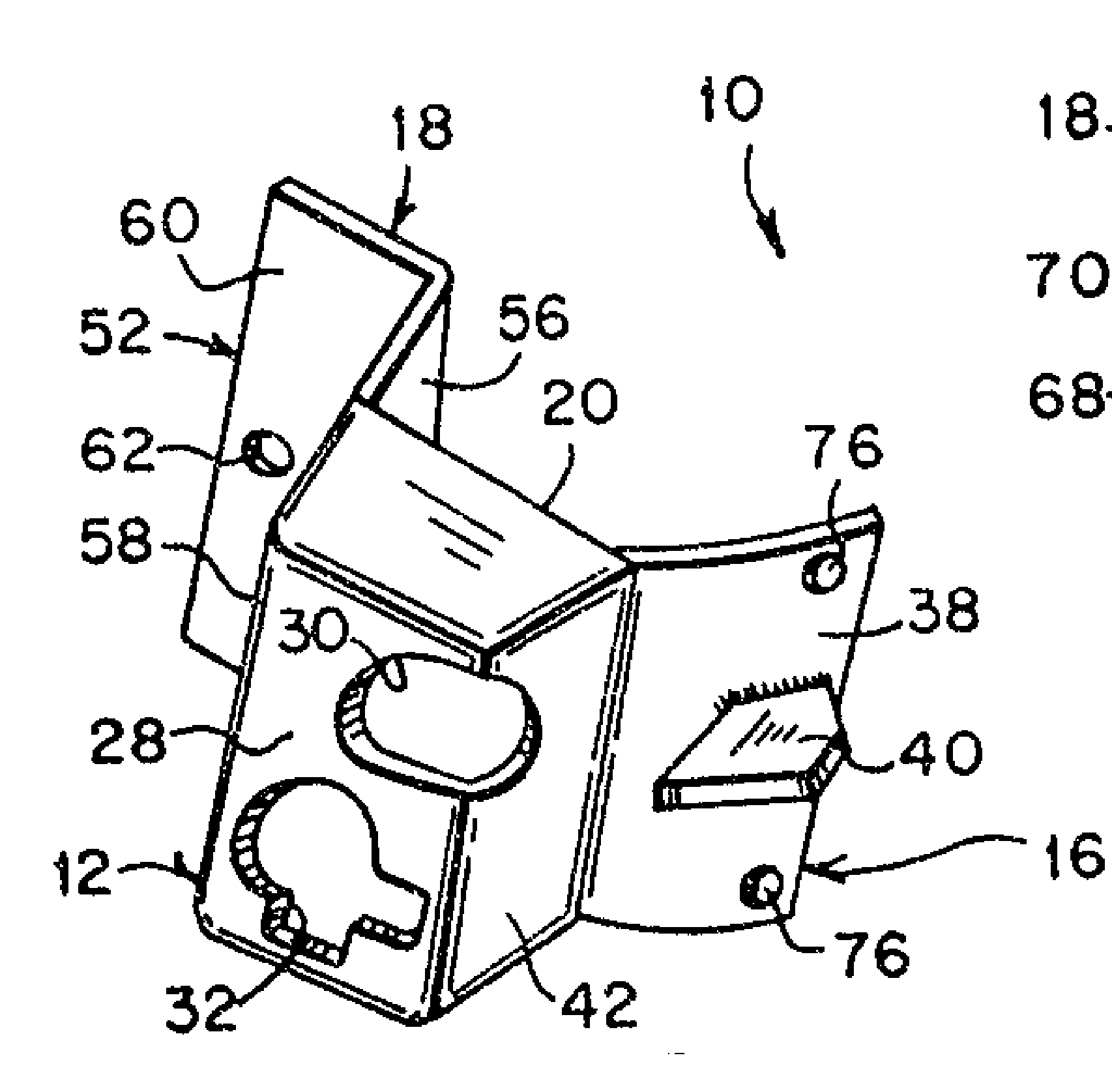
Figure 1 is a perspective view of tune instant invention
mounted and locked to a steering column of a motor vehicle
shown in phantom; and
Figure 2 is a perspective vie of the instant invention
per so removed from the steering column and separated into two
basic parts.
DETAILED DESCRIPTION OF THE EMBODIMENTS
Turning now descriptively to the drawings, in which like
reruns characters denote like elements throughout -the
several views, figure 1 and 2 illustrate an anti-theft
steering column cuff device 10 for automobiles and the like.
The device 10 contains a first box shaped casing 12, a second
box shaped casing 14, a hasp member 16 and a locking structure
lo.

S I! it J
The first box shaped casing 12 has an open side 20 to
fit against one side of a steering column 22 supporting a
steering wheel 23. The second box shaped casing 14 has a
curved open side 24 to fit against opposite side o-. the
steering column 22 as as to cover and protect an ignition
switch 26.
The hasp member 16 extends between the first box shaped
casing 12 and the second box shaped casing 14 so as to
removably connect the first box shaped casing 12 to the second
box shaped casillg 14 on the steering column 22.
The locking structure 18 extends between the first box
shaped casing 12 and the second box shaped casing 14 opposite
the hasp member 15 for locking the cuff device 10 to the
steering column 22 to prevent an unauthorized person from
operating the ignition switch 26.
The first box shaped casing 12 includes a base wall 28
opposite the open side 20 thereof, having two openings 30 and
32 there through, so that a tilt leerier 34 on the steering
column 22 can extend through opening 30 while a signal lever
36 on the steering column 22 can extend through other opening
32.
The hasp member 16 includes a curved plate 38 having a
hooked projection 40 thereon. The curved plate 38 is attached
to and extends away from an end wall 42 at the open side 20 of
the first box shaped casing 12. curved strap 44 having a
slot 46 t`nerethrolly'n is hinged at 48 to an end wall 50 at the
open side 24 of the second box shaped casing 14 so that the

Jo I f' )
slot 46 can Kit over the hooked projection 40 to be removably
connected thereto.
the locking structure 18 includes a first L-shaped
bracket 52 and a second L-shaped bracket 54. The first
L-shaped bracket 52 contains a first straight arm 56 forming a
continuance o-E an opposite end wall 58 of the firs-t box shaped
casing 12, while a second straight arm 60 having an aperture
62 there through extends at an angle away from the steering
column 22. Toe second L-shaped bracket 54 contains a first
straight arm 54 forming a continuance o-E an opposite end wall
66 of the second box shaped casing 14, while a second straight
arm 68 having an aperture there-through extends at an angle
away from the steering column 22 so that a shackle 72 of a
padlock 74 can extend through both of the apertures 62 and 70
and lock the L-shaped brackets 52 and 54 together about the
steering column 22~
In operative use, the first box shaped casing 12 is
fitted against the side of the steering column 22 with tilt
lever 34 the signal lever 36 extending through openings 30 and
32. The slot 46 is then placed over the hooked projection 40
so that the second box shaped casing 14 can swing down to
cover and protect the ignition switch 26. The shackle 72 of
the padlock 74 is then placed through the apertures 62 and 70
to lock the L-shaped brackets 52 and 54 together. To open the
cuff device 10 the padlock 74 is removed so that the second
box shaped casing 14 can be swung up and removed to expose the
ignition switch 26.

, Jo f ., Jo iffy I
The cuff device lo can be typically fabricated out of
durable stainless steel material. Rubber bumpers 76 can also
be provided on the curved plate 38 to properly position the
first box shaped casing 12 on the steering column 2 and
prevent damage thereto.
While certain novel features of this invention have been
shown and described and are pointed out in the annexed claims,
it will be understood that various omissions, substitutions
and changes in the forms and details of the device illustrated
and in its operation con be made by those killed in the art
without departing from the spirit of the invention.

Representative Drawing
A single figure which represents the drawing illustrating the invention.
Administrative Status

2024-08-01:As part of the Next Generation Patents (NGP) transition, the Canadian Patents Database (CPD) now contains a more detailed Event History, which replicates the Event Log of our new back-office solution.

Please note that "Inactive:" events refers to events no longer in use in our new back-office solution.

For a clearer understanding of the status of the application/patent presented on this page, the site Disclaimer , as well as the definitions for Patent , Event History , Maintenance Fee  and Payment History  should be consulted.

Event History

Description Date
Inactive: IPC expired 2014-01-01
Inactive: IPC removed 2013-12-31
Inactive: IPC assigned 2013-12-27
Inactive: IPC deactivated 2013-11-12
Inactive: IPC assigned 2013-01-14
Inactive: First IPC assigned 2013-01-14
Inactive: IPC assigned 2013-01-14
Inactive: IPC expired 2013-01-01
Application Not Reinstated by Deadline 1995-01-17
Time Limit for Reversal Expired 1995-01-17
Inactive: Adhoc Request Documented 1994-07-18
Deemed Abandoned - Failure to Respond to Maintenance Fee Notice 1994-07-18
Application Published (Open to Public Inspection) 1992-01-17
Request for Examination Requirements Determined Compliant 1991-12-13
All Requirements for Examination Determined Compliant 1991-12-13

Abandonment History

Abandonment Date Reason Reinstatement Date
1994-07-18
Owners on Record

Note: Records showing the ownership history in alphabetical order.

Current Owners on Record
NUNZIO EREMITA
NUNZIO EREMITA
Past Owners on Record
None
Past Owners that do not appear in the "Owners on Record" listing will appear in other documentation within the application.
Documents

To view selected files, please enter reCAPTCHA code :


To view images, click a link in the Document Description column (Temporarily unavailable). To download the documents, select one or more checkboxes in the first column and then click the "Download Selected in PDF format (Zip Archive)" or the "Download Selected as Single PDF" button.

List of published and non-published patent-specific documents on the CPD .

If you have any difficulty accessing content, you can call the Client Service Centre at 1-866-997-1936 or send them an e-mail at CIPO Client Service Centre.

({010=All Documents, 020=As Filed, 030=As Open to Public Inspection, 040=At Issuance, 050=Examination, 060=Incoming Correspondence, 070=Miscellaneous, 080=Outgoing Correspondence, 090=Payment})


Document
Description 
Date
(yyyy-mm-dd) 
Number of pages   Size of Image (KB) 
Abstract 1994-02-28 1 9
Claims 1994-02-28 2 55
Drawings 1994-02-28 1 25
Description 1994-02-28 6 151
Representative drawing 1999-06-28 1 33
Fees 1992-10-15 1 42
Fees 1991-09-15 1 36
Prosecution correspondence 1991-12-12 2 52
Examiner Requisition 1994-03-14 2 72
Courtesy - Office Letter 1992-02-13 1 45
Courtesy - Office Letter 1995-03-19 1 27
PCT Correspondence 1991-12-12 1 52