Note: Descriptions are shown in the official language in which they were submitted.
I
202124~
IMPROV~D SP8~RICAL ROTARY VALV~ ASSSM~LY POR AN
INT~RNAL COMBUSTION ~NGINE
FIELD O~ INVENTION
¦ This invention ~elates to an inte~nal combustion
engine of the piston and cylinder type and, more pa~ticulacly,
to a spherical fotary valve a~sembly foe the introduction
of the fuel and ai~ mixtuce to the cylindef and the evacuation
of exhaust gases. The improvement is di~ected to multi-port
;otary spheLical valves and an independent drip feed lubrica-
tion foc the valve shaft.
BACRGROUND O~ T~E INVENTION
In an intecnal combustion engine of a piston and
cylinder type, it is necessary to charge the cylindec with
a fuel and air mixture fo~ the combustion cycle and to vent
o~ evacuate the exhaust gases at the exhaust cycle of each
cylinder of the engine. In the conventional piston and cylinder
type engine, these events occuc thousands of times pef minute
pef cylindef. In the conventional internal combustion engine,
the cotation of a camshaft causes a ~priny-loaded valve to
open to enable the fuel and air mixtufe to flow from the cafbureto~
to the cylindef and the combustion chambef ducing the induction
stcoke. This camshaft closes thi~ intake valve ducing the
compression and eon~bustion ~tfoke of the cylinder and the
same camshaft opens another spring-loaded valve, the exhaust
valve, in ofdef to evacuate the cylindec afte~ compcession
and combustion have occucced. These exhaust gases exit the
cylindec and entec the exhaust Manifold.
The hacdwace associated with the efficient opecation
of conventional intecnal combustion engines having spring-loaded
valves includes items such as spfings, cotters, guides, cockec-
! shafts and the vaives themselves which a~e usually æositioned
i l
j ~
l 2021245
in the cylindec heads such that they normally opecate in a
substantially vertical positiorl, with their opening, descending
.. .
into the cylindec for the introduction oc venting or evacuation
of gases.
As the revolutions of the engine inccease, the valves
open and close more frequently and the timing and tolerarlces
become critical in order to prevent the inadvectent contact
of the piston with an open valve which can cause serious engine
damage. ~lith respect to the aforementioned hardwace and operation!,
it is rlormal pcactice for each cylindec to have one exhaust
valve ana one intake valve with the associated hardware mentioned -
heretofore; however, many internal combustion engines have
now progressed to multiple valve systems, each having the
~ ~- associated hardware and multiple camshafts.
~~ 15 In the standacd internal combustion engine, the
camshaft is rotated by the crankshaft by means of a timing
belt or chain. The operation of this camshaft and the as-
sociated valves operated by the camshaft presents the oppor-
tunity to decrease the engine efficiency to the friction as-
sociated with the operation of the various element3. Appli-
cant's invention is dicected towacds a novel valve means which
eliminates the need for spcing-loaded valves and the associated
hardware and in its simplest explanation, enlarges the camshaft
to provide for spherical rotary valves to feed each cylinder.
This decreases tha number of moving parts and hence the friction !
involved in the operation of the engine and increases engine
efficiency. It also eliminates the possibility of the piston
contacting an open valve and thus causing serious engine damage.
-- - Applicant's invention i9 applicable to utilization
of a single shaft containing a spherical cotary intake valve
and a spherical rotacy exhaust valve per cylinder. Applicant's
pending applications, Serial Nos. 270,027 and 409,037 ace
directed to a design in which the valve Mechanism operates
~x~
Ii ~
20212~5
at one-half the crankshaft speed. Applicant's pcesent dis-
- closuce is applicable to a multiple shaft arcangement wherein
the sphecical rotary intake valves are mounted on a first
shaft and the spherical rotary exhaust valves are mounted
on a second ~haft, the shafts being in substantial parallel
'alignment and geared between the ccankshaft and each valve
shaft to provide for normal half speed rotation with the
crankshaft or quarter speed cotation with the ccankshaft or
one-eighth speed rotation with the crankshaft depending upon
the portirlg of the rotacy spherical valves. The lubrication
of this system is accomplished by a drip feed to the spherical
rotary valve bearings through the support shaft.
I OBJ~CT OF THE INVENTION
15 1 An object of the pcesent inverltion is to pcovide
for a novel and unique valve mechanism for inter~nal com-
bustion engines which eliminates the need for spring-loaded
valves.
; Another object of the present invention i8 to pro-
vide a novel and unique valve mechism for internal combu~tion
engines which increases the efficiency of the engine.
Another object of the present invention is to provide
a novel and unique valve mechanism for i~iternal combu~tion
engines which decreases the friction generated by an internal
combustion engine and increases the efficiency of the engine.
A still fucthec object of the pcesent invention
is to provide foc a novel and unique valve mechanism foc an
internal coMbustion engine which has fewer moving parts and
I thus permits the engine to operate at higher revolutions per
minutes.
` ~ A still further object of the present invention
is to provide foc a novel and unique valve mechani~m for in-
ternal combustion engines which operates at substantially
I! i
202~2~5
lower revolutionR per minute than the crankshaft.
A still further object of the present invention
i9 to provide for a novel and unique valve mechanism for an
internal combustion engine which can be utilized with internal
~combustion enyines which are fuel-injected or carbureted.
A still fruther object of the present invention
is to provide for a novel and unique valve mechanism for in-
ternal combustion engines which does not eequire pressurized
lubrication.
A still further object of the present invention
is to provide for a novel and unique valve mechanism for ln-
ternal combustion engines in which the valve mechanism is
multi-shafted and the intake valves and exhaust valves afe
segregated.
15 ,
SUMMARY OF THE INVENTION
An imprQved rotary valve assembly for use in internal
combustion engines involving a two-piece cylinder head accom-
' modating rotary intake valves and rotary exhaust valves mounted
on independnet shafts, operatiny at one-quarter speed of tne
crankshaft rotatiorl with each of the rotary intake valves
and rotary exhaust valves having two passageways for the intro-
duction and interruption of fuel/air mixture into the cylinder
and the evacuation and interruption of evacuation of the spent
gases from the cylinder, respectively, the lubrication of
the rotary valve assembly beiny by a drip feed through a longi-
;tudinal conduit in each respective shaft and radial conduitsin each ~espective shaft in regi~tration with the bearlng
mean~ ~upportlllg the sha~t withil~ the cylinder head.
.~ i.
20212~ l
`:
BRIEF DBSCRIPTION OF T~E DRAWINGS
These and other advantages and improvements wili
be evident especially when taken with the following drawings
' wherein:
Figure 1 is an exploded view of the impcoved sphecical
cotary valve assembly;
Figure 2 is a top, pl-aner partial cutaway view,
of the intake valve and shaft assembly;
Figure 3 is a ~ide, cutaway view of the beacing
means for the spherical rotary valve assembly.
Fisufe 4 is an end view.
Figure S is an end view of the beacing means mounted
,-i-- on the shaft for the cotary valve asAembly.
Figure 6 is a front view of a spherical intake valve.
Figure 7 is a side cutaway view along plane 8-8
of Fisure 7 of a spherical intake valve.
Figure 8 is a perspective view of a spherical inta~e
valve.
Fiyure 9 is a side elevational view of a spherical
exhaust valve.
Figure 10 is a front cutaway view of a spherical
exhaust valve along plane 9-9 of Figure 9.
Figure 11 is a perspective view of a sphecical exhaust
valve.
25 ' Figure 12 is a schematic cutaway view of the gear
mechanism for the sphecical cotary valve assembly.
il ~
2021245
Figure 13 is a cross sectional end view of the spherical
valve assembly showing the relationship between the spherical
intake valve and the spherical exhau~t va]ve during the introduction
of the fuel/air mixture.
5 ,. Figure 14 is a cross sectional end view of the cotary
valve ass~mbly showing the celationship between the ~pherical
intake valve and the spherical exhaust valve duriny the évacuation~
of spent gases.
1.
20212~
, DETAIL~D DESCRIPTION O~ THE DRAWINGS
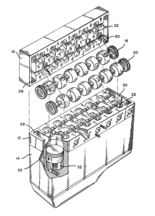
Referring tv Figure 1, there is shown an exploded
view of the spheLical rotary valve assembly. The assembly
comprises a split head comprising a lower section 12 secured
to engine block 14 and an upper split head section 16 which
is secufed to lower split head section 12. Split head assembly
sectionq i2 and 16 are designed to accommodate an intake spherical
rotaey valve assembly 18 and an exhaust spherical rotary valve
assembly 20 in drum accommodating cavities 22. As can best ~
~ be seen in Figure 1, lower split head assembly 12 contains
one-half of the drum accomrnodating cavities 22 for the intake
spherical valve assembly 18 and exhaust sphetical valve assembly
' 20 and upper split head assembly 16 contains the other half
~ of drum accommodating cavities 22 for the respective intake
spherical valve assembly 18 and exhaust spherical valve assembly
20 such that when lower split head section 12 and upper split
head section 16 are secured, the intake spherical drum assembly
18 and exhaust spherical drum assembly 20 are positioned such
that the intake spherical valves 24 and the exhaust spherical
20 I valves 26 are enclosed in the respective drum accommodating
cavities 22.
Additionally, the longitudinal ends of lower split
head assembly 12 and upper split head a~sembly 16 contain
cavities 28 and 30 for accommodation of the gearing mechanism
. .
,-~~ 25 for intake spherical drum assembly 18 and exhaust spherical
dcum asselnbly 20 as described hereafter. Cylinder 32 and
piston 23 contained within cylinder 34 are positioned in engine
block 14.
, Referring to Fiyure 2, there is shown a top planer
partially cutaway view of intake spherical drum assembly 18
positioned in lower split head section 12. There is one spheri-
cal intake valve 24 associated with each cylinder 32 in engine
202124~
block 14~ Intake spherical valves 24 ace mounted on shaft
means 34 with a bearing positioned on shaft 34 between ad-
! jacerlt sphecical intake valves 24. The beacing means 36 com-
pfi~es a cylindrical bearing housing 33 having circumfecential-
ly disposed thereirl, a plurality of needle roller beacings
40, in contact with shaft 34 which will rotate on needle collec
beacings 40. Baaring means 36 i9 positioned between drum
accommodating cavities 22 and lowec split head section 12
and upp^r split head section 16 in cylindcical cavities 42
which extend between adjacent drum accommodating cavities
22.
Intake spherical rotary valves 24 are secured
to shaft 34 so as to rotate with shaft 34. Figu~es 3, 4 and
, 5 a~e a side cross sectional, end view and end view on shaft
'.j 34 respectively of bearirlg means 36. Shaft 34 has defined
through its longitudinal axis, a conduit 46 fo~ the lubrication
of beacing means 36. In this configuration, thè oil sump
pump provides oil to conduit 46 at one longitudinal end of
shaft 34. The oil passes through conduit 46 which has ap-
pcopriately placed tfansverse conduits 48 positioned to coin-
cide with bearing means 36 thus directing oil from conduit46 through transverse conduit arm 48 to needle coller bearing
sucface 40. Excess oil passes through longitudinal conduit
46 and returns to the oil sump. In this configuration, oil
is provided to needle roller bearings 40 thcough a drip process
supplying oil as needed to needle ~oller bearings 40. Oil
is thus segregated frorn the inta~e spherical rotary valve
and exhaust spherical totary valve which do not require the
lubrication as a result of the sealing mechanism described
hereafter. A pair of qeals 50 are positioned at each end
of bearing rneans 36, one such seal 50 will be in proximate
contact with either an exhaust sphecical drum 26 or intake
spherical drum 24, respectively and the othec seal contacting
' ,
.,
Il
202~24~
a recess lip 52 thu~ maintainitlg the seal in position.
Referring to Figuce o, there is shown a front view
of intake spherical valve 24, Figure 7 is side cutaway view
of intake spherical valve 24 along plane 8-8 of Figure 7 and
S Figure 8 tepcesents a perspective view of intake spherical
valve 24. Intake spherical valve 24 is defined by an arcuate
sphecical circumferelltial uesiphery 60 and planer sidewalls
62 and 64. Intake spherical valve 24 has centrally disposed
apecture 66 for mounting intake the spherical valve 24 on
shaft 34 of intake s?hecical valve assembly 18. The centrally
disposed aperture 66 can be of a splined configuration to
interlock with a splined configucation on shaft 34 or may
be mounted by other conventional means. It will be recognized
by those skilled in the aft, however, that the mounting method
for intake spherical valve 24 may vacy and may in fact utilize
a locking key type mechanism to secuce intake spherical valve
24 to shaft 34.
Disposed inwardly from planec 4idewall 64 is a annular
U-shaped Of doughnut cavity 68 which extends from planee sidewall
64 to a depth approximate to planec sidewall 62.
Positioned on spherical circumferential psriphery
60 of intake spherical valve 24 are two apertures 70 positioned
180 apart, aperture 70, providing a pa~sageway from spherical
circumfetential peciphery 60 to annular U-Ahaped or doughnut
cavity 68. In thi~ configuration, intake spherical valve
24 is shown with two apertuces 70 on ciccumferential periphery
60 is designed to pcovide foc the intaks sphefical valve 24
. to opecate at 1/4 speed of that of the engine crankchaft.
A single apertuce 70 on intake spherical valve 24 would allow
the intake spherical drum 24 to operate at 1/2 the speed of
the engine crankshaft under proper gear ratioing as described
¦ heceafter. Aperture 70 on sphecical circumferential periphery
60 of intake sphecical valve 24 are designed to be placed
.,
!~ .
202124~
in sequential eotaey alignment with the inlet port to the
cylinder as described hereafter in order to pcovide a fuel/aie
charge to the cylindee.
' It should be noted that planer sidewall 62 of intake
spherical valve 24 would be in contact with seal 50 of bearing
means 36 which would be positioned on shaft 34 immediately
adjacent intake spherical valve 24. Such bearing means 34
would be positioned immediately adjacent planer sidewall 62
of each of intake spherical valves 24 along shaft 34 as shown
in Fiyuce 1.
Referring to Eigures 9, 10 and 11, there is shown
a side elevational view of exhaust spherical valve 26, a front
cutaway view of exhaust sphericai valve 26 and a perspective
view of exhaust ~pherical valve 26, respectively. Exhaust
spherical valve 26 has an arcuate spherical circumferential
periphery 80 having irltersecting planer sidewalls 82 and 84.
Centrally-disposed through exhaust spherical valve 26 is an
aperture a6 foe the mounting of exhaust spherical valve 26
on shaft 34. Again, aperture 86 may be of a splined con-
figuration, however, other configurations would be acceptablein order to ensure that exhaust spherical valve 26 would rotate
with shaft 34.
Exhaust spherical valve 26 ha~ defined therethrough,
two exhaust conduits 88 and 88A. Exhaust conduit 88 and 88A
ace defined by an aperture 90 and 90A on the spherical pe-
riphery 80 of exhaust spheeical valve 26. Second aperture~
92 and 92A are po~itioned on planer sidewall 84 of exhaust
spherical valve 26. Apertures 90 and 90a are designed to
come into sequential rotary alignment with the exhaust port
; 30 of the cylinder for the evacuation of exhaust gases. As such,
apertues 90 and 90A are positioned approximately 180 apart
on exhaust spherical valve 26 in order that exhaust spherical
valve 26 can rotate at 1/4 the speed of the engine crarlkshaft
under the yearing ratios desceibed hereafter.
20212~
Refecring to Figure 12, there is shown a schematic
of the drive and gear mechanism for the ~pherical rotacy valve
as~embiy in operation at 1/4 speed in relationship to the
crank-shaft. The crankshaft driving gear 100 would be in
communicatiotl by belt drive or chain drive with idler gear
, 102. Idler year 102 is mounted on intake spherical valve
1 assembly 18 and, in particular, on shaft 34 which supports
--~ intake spherical valves 24. However, idler geac 102 does
not drive or rotate shaft 34. Idler gear 102 is in communi-
cation with drive gear 104 mounted orl the same longitudinal
end of shaft 34 of intake spherical valve assembly 18. Gear
104 is in communication with drive gear 106 mounted on shaft
34 of exhaust spherical valve assembly 20. Drive gear 106
j is secured to shaft 34 of the exhaust spherical valve assembly
15 1 20 ana drives shaft 34 or rotates shaft 34 causing the exhaust
spherical valves to rotate. Mounted on the opposite longi-
tudina] end of shaft 34 of exhaust spherical drive assembly
20 is drive gear 108 which is in communication with an identical
drive gear 110 Mounted on the opposite longitudinal end of
intake spherical drive assembly 18. Drive gear 108 com-
municates with drive gear 110 and causes shaft 34 of the intake
spherical valve assembly 18 to rotate thus driving or rotating
the intake spherical valves 24.
The drive assembly thus follows the following path,
25 I crankshaft gear 100 communicates with idler gear 102 which
drives drive gear 104 which in turn drives gear 106 rotating
shaft 34 of the exhaust rotary valve assembly, gear 108 of
the exhaust spherical valve assembly drivin~ gear 110 on the
intake spherical valve assembly 18 causing shaft 34 of the
intake Rpherical valve assembly to rotate thus causing the
rotation of the intake spherical valves 24.
/~
202124
The gearing catio for this quarter speed assembly
is as follows: dcive gear 100 to idler gear 102, 1:2; idler
gear 102 to drive gear 104, 2:1; drive gear 104 to drive gear
106, 1:2 and drive gear 108 to drive geac llO, 1:1.
In this quarter speed embodiment, the intake spherical
valves 24 would have two apertures on the sphecical periphery
of the valve for registration with the inlet port to the cylinder
The exhaust spherical valve 26 would have two passageways
thecethrough, each having an aperture on the periphery of
the exhaust spherical valve 26 for registration with the outlet
port cf the cylinder for the evacuation of gases.
- Figure 13 is an end view of the rotary valve assembly
showing the relationship of the intake spherical valve 24
and exhaust spherical valve 26 during the introduction of
the fuel/air mixture into cylinder 32. Intake spherical valve
24 and exhaust spherical valve 26 are shown positioned in
drum accommodating cavities 22 mounted on shafts 34. Doughnut
or U-shaped cavity 68 in intake spheeical valve 24 is in com-
munication with the engine inlet port 120 which introduces
fuel/aic mixture into U-shaped or doughnut cavity 68 con-
tinuously. The fuel/air mixture would be mixed prior to in-
troduction by means of a carburetor or the positioning of
a fuel injector means immediately before intake spherical
valve 24. In this configuration, U-shaped or doughnut cavity
68 is continually charged with a fuel/air mixture. In ~igure
13, engine inlet port 120 is shown as being positioned in
the lower portion of the split head a~sembly. The positioning
of engine inlet port 120 is a matter of choice depending upon
the manner in which the fuel/air mixture is mixed, i.e., car-
buretoc or fuel injection. The engine inlet port 120 couldbe positioned in the upper poction of split head assembly
wihout departing from the spirit of the invention. As can
- 20212~
be seen in Figure 13, intake spherical valve 24 cotates about
shaft 34 within drum accommodating cavities 22 and contacts
a sealing ring 122 positioned annularly circumferentially
about cylinder inlet port 124.
Exhaust spherical valve 26 is similarly mounted
on a shaft 34 in contact with a sealing eing means 124 which
is circumferentially positioned about cylinder exhaust port
126. As shown in Figure 13, exhaust spherical valve 26 is
in a closed position with exhaust poet 126 sealed by the outer
periphery 80 of exhaust spherical valve 26. Intake spherical
valve 24 is in the open position with one of its two periph-
erally located apertures 70 in registration with inlet port
124 to cylinder 32. The fuel/air mixture is therefoee being
introduced into cylinder 32 by means of engine inlet port
120 into the split head, and the doughnut or U-shaped cavity
68 within intake spherical valve 24 and peripheral aperture
70 on intake spherical valve 24. Cylinder 32 would be charged
with a fuel/air mixture during aperture 7018 registration
with inlet port 124. Piston 33 would be at its lowermost
position within cylinder 32 when the cylinder was fully charged.
At that point in time, aperture 70 on intake spherical valve
24 would have moved out of registration with inlet port 124
thus sealing inlet port 124. While inlet port 124 and outlet
port 126 were respectively sealed, piston 33 would begin its
- 25 upward movement compressing the fuel/air mixture and ignition
would occur by means of spark plug 130 positioned in the ex-
haust port 126. Piston 33 would be driven downwardly within
cylinder 32 and then commence an upward stroke for the evacu-
ation of the exhaust gases.
Figure 14 shows that intake spherical valve 24 still
maintains inlet port 124 in a closed position, but exhaust
spherical valve 26 has now moved such that peripheral aper-
ture 90 is in registration with cylinder exhaust port 126
202124~
permitting the evacuation of the exhaust gases by means of
exhaust conduit 88 to exhaust port 132. Upon the complete
evaluation of the gases, exhaust conduit 88 would move out
of eegistration with exhaust port 126 and the second inlet
port 70 on the periphery 60 of intake spherical valve 24 would
move into registration with inlet poct 124 for the reintro-
duction of the fuel/air mixture.
In this configuration, the intake spherical valve
- 24 and exhaust spherical valve 26 would move at one-quarter
of the speed of the crankshaft as a result of having two inlet
apertures and two exhaust conduits contained within each valve
respectively. The gearing foc such a quarter speed mechanism
is as disclosed in Figure 12.
The ability to operate the engine with the valve
assembly operating at one-quarter speed allows for less wear
on the valve mechanism, cooler operating temperatures, and
less maintenance problems.
The intake spherical valve 24 and exhaust spherical
valves 26 eotate with shaft 34, shaft 34 being supported by
bearing means 36. The bearing means are lubricated by the
drip feed system previously described. Intake spherical
valves 24 and exhaust spherical valves 26 within drum accom-
modating cavities 22 contact sealing rings 122, sealing rings
122 being annularly positioned about the cylinder inlet port
and inlet cylinder exhaust port. Sealing eings 122 have an
arcuate surface which conforms to the peripheral surface 60
and 80, respectively of intake spherical vaIve 24 and ex-
haust spherical valve 26. Sealing rings 122 as described
in the prior identified applications by applicant, provide
a seal with the respective valves during the compcession or
power stroke.
202124~
In the configuration as disclosed herein, Appli-
cant has achieved a one-quartec speed valve mechanism in re-
lationship to the rotation of the crankshaft by utilizing
two intake conduits on each of the cotacy exhaust valve and
rotary intake valve and by establishing the rotary intake
valve and the rotary exhaust valve on separate shafts. One
shaft would be driven by communication with the crankshaft.
This shaft in turn, through an idler drive gear, would rotate
the opposing shaft which in turn would rotate the first shaft
from the opposing longitudinal end.
Applicant's rotary intake valve and cotary exhaust
valve are in gas tight sealing contact with seals 122 in drum
accommodating cavities. The lubrication required is that
of the bearing surfaces which support the rotary intake valves,
rotary exhaust valves and the shaft. These bearing surfaces
are positioned adjacent to the rotary intake valve and rotary
exhaust valve, respectively and are qealed at their ends.
The lubrication for these bearing surfaces is by means of
a drip feed system in which the oil from the sump passes down
a longitudinal conduit within shaft 34 and directed by tcans-
verse conduits in shaft 34 to the needle bearings within the
bearing means. Excess lubcication passes through the longi-
tudinal conduit in shaft 34 and returns to the oil sump.
It will be recognized by those skilled in the art
that depending upon engine size, increasing the dimensions
of the rotary intake valve and the rotary exhaust valve would
pecmit the utilization of additional conduits for the intro-
duction of fuel/air mixture or the evacuation of the fuel/air
mixture, thus permitting the valves to rotate at an even lesser
speed relative to the crankshaft.
It will be recognized by those skilled in the art
that the apparatus has been described in connection with the
exemplary embodiments thefeof and it will be understood that
- 20212~r
many modifications will be apparent to those of ordinacy skill
in the art and this application is intended to cover any adapta-
tions or variations thereof. $herefoee, it is manifestly
intended that this invention be only limited by the claims
and equivalents thereof.