Note: Descriptions are shown in the official language in which they were submitted.
2021~6~
COv~ FOR AIR BAG UNIT
BACKGROUND OF THE lNV~N'l'ION
1. Field of the Invention
The present invention relates to a cover for an air bag
unit which is attached to a motor vehicle so as to house an air
S bag, which is inflated on a prescribed occasion.
2. Description of the Related Art
A conventional cover for an air bag unit is disclosed in
the Japanese Utility Model Application (OPI) No. 44861/89 (the
term "OPI" as used herein means an "unex~mined published
lo application"). The conventional cover is made of a
softsynthetic resin, and includes an upper portion and a side
portion. The upper portion covers an air bag, which is
inflated on a prescribed occasion, and is broken when the air
bag is inflated. The side portion extends downwardly from the
peripheral edge of the upper portion. The cover has an insert
embedded therein which includes a flexible net and a flexible
reinforcing band assembly of high tensile strength.
The net includes a nearly-oblong annular side portion
em.bedded in the side portion of the cover, upper portions
embedded in the upper portion of the cover except in the
breakable part of the upper portion of the cover, and coupling
portions which couple the side portion of the net to the upper
portion thereof. The net is embedded in the cover so that the
-- 1 --
2021~6~
upper portions of the net do not separate from the side portion
thereof when the upper portion of the cover is broken due to
inflation of the air bag.
The reinforcing band assembly includes a horizontal band
secured to the side portion of the net along the entire
perimeter of the side portion, and vertical bands secured to
the side edge parts of the coupling portions of the net and to
the horizontal band. The horizontal band is provided to
prevent the side portion of the cover from expanding outward
lo when the air bag is inflated. The vertical bands are provided
to reinforce the coupling portions of the net and the side
portions thereof under the coupling portions, because the
coupling portions are forcefully pulled upwardly when the upper
portion of the cover is broken and spreads due to the inflation
of the air bag. To enhance the tensile strength of the
coupling portions of the net and of the side portion thereof
under the coupling portions, the vertical bands are long enough
to extend down from the side edge parts of the coupling
portions of the net to locations under the side portion of the
net along the horizontal band and be secured at the lower ends
of the vertical bands to the body of a steering wheel. Since
the vertical bands, which are expensive are long, the cost of
the material for the cover is high which presents a problem.
In addition, the vertical bands need to be secured to the body
of the steering wheel, and the area of the portions of the
vertical bands which are sewn to the side portion of the net is
20Z126~:
large due to the large length of the vertical bands.
Therefore, the number of manufacturing steps for the cover and
the cost of manufacturing are high which is also a problem.
S~lMMARY OF THE INVENTION
The present invention has the object of solving the above-
mentioned problems with the conventional cover.
Accordingly, it is an object of the present invention to
provide a cover for an air bag unit in which vertical bands and
sewn portions are shortened without reducing the tensile
o strength of the coupling portions of a net and of the side
portion under the coupling portions, which enable the coupling
portions and the side portion to withstand stress well at the
time of the inflation of an air bag, so that the cost of the
material for the cover, the number of the steps for
manufacturing the cover and the cost of manufacturing are
minimized.
The cover of the invention is made of a soft synthetic
resin, and includes an upper portion and a side portion
extending downwardly from the peripheral edge of the upper
portion. The upper portion of the cover covers the air bag,
which is inflated on a prescribed occasion, and is broken when
the air bag is inflated. An insert including the flexible net
and a flexible reinforcing band assembly of high tensile
strength is embedded in the cover, the net incudes an annular
2s side portion embedded in the side portion of the cover, upper
-- 3 --
20Z1~6~
portions embedded in the upper portion of the cover except for
the breakable part of the upper portion and the coupling
portions coupling the side portion of the net to the upper
portions thereof. The reinforcing band assembly includes a
s horizontal band sewn to the side portion of the net along the
entire perimeter of the side portion of the net, and vertical
bands sewn to the side edge parts of the coupling portions of
the net and to the horizontal band. The cover is characterized
in that the vertical bands of the reinforcing band assembly are
lo bent back at the lower portions thereof so that the lower
portions surround the horizontal band of the assembly; and the
vertical bands, the horizontal band and the net are sewn to
each other including the bent-back lower portions of the
vertical bands.
When the air bag is inflated so that the upper portion of
the cover is broken, the coupling portions of the net of the
cover are pulled so that the vertical bands of the reinforcing
band assembly are pulled upwardly and the horizontal band is
pulled by the bent-back lower portions of the vertical bands.
At that time, since the horizontal band is sewn to the side
portion of the net along the entire perimeter of the side
portion, the tensile forces which act to the vertical bands are
distributed to the horizontal band so that the strength of the
cover is great enough to withstand the tensile forces which act
on the coupling portions of the net. For that reason, the
vertical bands do not need to be made so long as to extend down
20Z126~
from the side portion of the net and be secured to the body of
a steering wheel as in the conventional cover. Rather, the
vertical bands can have such a small length that the vertical
bands simply have bent-back lower portions extending around the
horizontal band. Since only the horizontal and the vertical
bands and the side portion of the net are sewn to each other
including the bent-back lower portions of the vertical bands,
the sewing of the cover is minimized. The manufacturing steps
and the cost of manufacturing are thus reduced.
lo Although the vertical bands of the conventional cover are
sewn together with the net thereof to the horizontal band of
the cover, the vertical bands do not surround the horizontal
band but are only sewn thereto by sewing thread. When the
conventional cover is broken due to the inflation of the air
bag, the sewing thread is elongated so that the tensile forces
which act on the vertical bands cannot be distributed to the
horizontal band. In contrast, the vertical bands of the cover
provided in accordance with the present invention are shortened
without reducing the tensile strength of the coupling portions
of the net and the side portion, which enables the coupling
portions and the side portion to withstand the tensile forces
which act to them when the air bag is inflated. In addition
the vertical bands of the cover do not need to be secured to
the body of the steering wheel. As a result, the cost of the
2s material for the cover, the number of manufacturing steps and
the cost of manufacturing are reduced.
~o~ 6~
In one aspect, the present invention provides an insert
for a cover for an air bag unit comprising: a flexible net
including first and second upper portions, having edges
adjacent to a side portion; and a flexible reinforcing band
assembly coupled to said flexible net, said reinforcing band
assembly including a horizontal band element coupled to and
extending along and about the entire side portion of said
flexible net and plurality of vertical band elements, each
said vertical band element having a first longitudinal end
and a second longitudinal end, said first longitudinal end
of each said vertical band being coupled to an edge of one
of said first and second upper portions adjacent to said
side portion, said second longitudinal end of each said
vertical band being bent back so as to surround said
horizontal band, said horizontal band, said side portion of
said net and said bent back portions of said vertical bands
being coupled together.
In another aspect, the present invention provides a
cover for an air bag unit comprising: a cover upper portion
for covering an air bag of said air bag unit and formed ~o
as to be broken when the air bag is inflated; a cover side
portion extending downwardly from a peripheral edge of said
upper portion, and an insert embedded in said cover said
insert including a flexible net including first and second
upper portions having edges adjacent to a side portion; and
a flexible reinforcing band assembly coupled to said
flexible net, said reinforcing band assembly including a
horizontal band element coupled to and extending along and
- 5a -
202 1 26~
about the entire side portion of said flexible net and
plurality of vertical band elements, each said vertical band
element having a first longitudinal end and a second
longitudinal end, said first longitudinal end of each said
vertical band being coupled to an edge of one of said first
and second upper portions adjacent to said side portion,
said second longitudinal end of each said vertical band
being bent back so as to surround said horizontal band, said
horizontal band, said side portion of said net and said bent
10 back portions of said vertical bands being coupled together.
- 5b -
20~1~6~
Other objects, features, and characteristics of the present
invention, as well as the method of operation and functions of
the related elements of the structure, and the combination of
parts and economies of manufacture, will become more apparent
upon consideration of the following description and the
appended claims with reference to the accompanying drawings,
all of which form a part of this specification, wherein like
reference numerals designate corresponding parts in the various
figures.
10DESCRIPTION OF THE DRAWINGS
Fig. 1 is a sectional view of a cover provided in
accordance with the present invention;
Fig. 2 is a perspective view of the cover; and
Fig. 3 is a perspective view of the insert for the cover.
15DETAILED DESCRIPTION OF EXEMPLARY EMBODIMENT
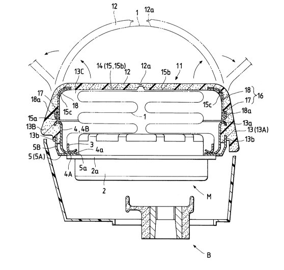
Figs. 1 and 2 show a cover ll provided in accordance with
the invention and which is for an air bag 1. The cover 11 is
made of a soft synthetic resin such as urethane, and has an
insert 14 embedded in the resin. The cover 11 is shaped like
a box so as to cover the folded air bag 1, and includes an
oblong upper portion 12 and a side portion 13 extending
downwardly from the peripheral edge of the upper portion. The
cover ll is disposed over the boss B of a steering wheel. On
a prescribed occasion, the air bag 1 is substantially
2021~6~
spherically inflated by a gas supplied from an inflator 2. An
annual metal fastener 3 is provided at the bottom of the air
bag l, and secured together with a support base 4 and a holder
5 to the flange 2a of the inflator 2 by bolts, rivets or the
like (not shown).
The upper portion 12 of the cover 11 has breakable part 12a
which is substantially I-shaped when viewed from above. As a
result, the upper portion 12 can be easily broken when the air
bag 1 is inflated. The side portion 13 of the cover 11 has an
o engagement groove 13a which is defined in the inside and along
the entire perimeter thereof and has an arc-shaped cross
section. The side portion 13 is composed of side parts 13A,
13B, 13C and 13D, each of which also has an engagement groove
13b extending vertically in the central portion of the side
part from the bottom of the central portion. The support plate
4 and the holder 5 are fitted in the engagement grooves 13a and
13b, respectively, so that each of the side parts 13A, 13B, 13C
and 13D of the side portion 13 is pinched between the support
plate 4 and the holder 5. As a result, the cover 11 is
fastened to the support plate 4.
The holder 5 is a metal plate to firmly hold the cover 11
on the support plate 4. The holder 5 includes a lower portion
5a which is substantially cross shaped when viewed from above,
and four side portions 5B extending upwardly from the four
outer edges of the lower portion and fitted in the engagement
grooves 13b of the side parts 13A, 13B, 13C and 13D. Finally,
20~6~
the central part of the lower portion SA has an insertion hole
5a into which the inflator 2 is inserted.
The support plate 4 is a metal plate, and is substantially
oblong dish-shaped. The support plate 4 includes a lower
portion 4A which is oblong shaped when viewed from above, and
four side portions 4B extending upwardly from the entire
peripheral edge of the lower portion and fitted in the
engagement grooves 13a of the side parts 13A, 13B, 13C and 13D.
The central part of the lower portion 4A has a circular
insertion hole 4a into which the inflat-or 2 is inserted. The
peripheral part of the lower portion 4A of the support plate 4
is provided with a securing means such as puts (not shown) so
that an air bag unit M including the air bag 1, the inflator 2,
the metal fastener 3, the support plate 4, the holder 5 and the
cover 11 are secured by the means over the boss ~ of the
steering wheel.
The insert 14, which is embedded in the cover 11, is
composed of a net 15 woven from a spun yarn such as a nylon
yarn, a polyester yarn and a cotton yarn, and a reinforcing
band assembly 16 woven from aramid fibers or the like which are
higher in tensile strength than the spun yarn. The net 15 is
about 3 mm in the length of every side of each mesh thereof,
and includes an oblong side portion 15a embedded in the entire
side portion 13 of the cover 11, two upper portions 15b
embedded in the upper portion 12 of the cover except in the
breakable part 12a thereof, and coupling portions 15c which
202~6~
couple the sideportion 15a and the upper portions 15b, as shown
in Figs. 1, 2 and 3. The reinforcing band assembly 16 includes
a horizontal band 17 sewn to the side portion 15a of the net 15
along the entire perimeter thereof by a sewing thread 19, such
as a nylon thread, and vertical bands 18 sewn to the side edge
parts of the coupling portions 15c of the net by sewing threads
19, such as nylon threads. Each of the vertical bands 18 is
bent on the upper portion 15b of the net 15 at the upper
portion of the vertical band and bent back around the
o horizontal band 17 at the lower portion of the vertical band.
The vertical bands 18, the horizontal band 17 and the side
portion 15a of the net 15 are sewn to each other, including the
vent-back lower portions 18a of the vertical bands, with sewing
threads 19.
When the cover 11 is to be manufactured, the vertical and
the horizontal bands 18 and 17 of the reinforcing band assembly
16 are secured in prescribed positions to the net 15, the
insert 14 thus composed of the net and the reinforcing band
assembly is set in a prescribed die, and a prescribed molding
material is poured into the die. The cover 11 is thus
manufactured through molding.
The folded air bag 1 is secured to the inflator 2 and the
support plate 4 by the metal fastener 3. The cover 11 is
fastened to the support plate 4 by using the engagement groove
13a of the side portion 13 of the cover. The holder 5 is
fitted in the engagement groove 13b of the side portion 13 of
_ g _
202126~
the cover 11 and secured to the support plate 4. The air bag
unit M thus assembled is disposed with the securing means on
the support plate 4 over the boss B of the steering wheel.
On the prescribed occasion after the disposition of the air
bag unit M, the air bag 1 is inflated and the breakable part
12a of the upper portion 12 of the cover 11 is broken. As a
result, the coupling portions 15c of the net 15 are pulled so
that the vertical bands 18 of the reinforcing band assembly 16
are pulled upwardly. At that time, the horiæontal band 17 of
the band assembly 16 is pulled by the bent-back lower portions
18a of the vertical bands 18. Since the horizonal band 17 is
sewn to the side portion lSa of the net 15 along the entire
perimeter thereof, the tensile forces which act to the vertical
bands 18 are distributed to the horizontal band so that the
strength of the cover 11 is great enough to withstand the
tensile forces which act on the coupling portions 15c of the
net. For that reason, the vertical bands 18 do not need to be
made so long as to extend down from the side portion 15a of the
net 15 and be secured to the body of the steering wheel as in
the conventional cover, but may be of such a small length that
the vertical bands have the bent-back lower portions 18a simply
extending around the horizontal band 17. Since only the
horizontal and the vertical bands 17 and 18 and the side
portion 15a of the net 15 are sewn to each other, including the
bent-back lower portions 18a of the vertical bands, the sewing
of the cover 11 is minimized. In addition, the vertical bands
-- 10 --
20~1~6~
18 do not need to be secured to the body of the steering wheel.
The number of manufacturing steps for the cover 11 and the cost
of manufacturing are thus reduced. If the reinforcing band
assembly 16 is made of aramid fibers, the cost of the assembly
is relatively high. However, the amount of aramid fibers
required for the vertical bands 18 of the invention will be
about 20% less than that required for the vertical bands of the
reinforcing band assembly of the conventional cover, and the
cost of the material for the insert 14 will be about 18% less
lo than that for the insert of the conventional cover.
While the invention has been described in connection with
what is presently considered to be the most practical and
preferred embodiment, it is to be understood that the invention
is not to be limited to the disclosed embodiment, but on the
contrary is intended to cover various modifications and
equivalent arrangements included within the spirit and scope of
the appended claims.
For example, while in the illustrated embodiment each upper
portion 15b of the net 15 is larger in length than each
coupling portion 15c thereof, the upper portion may be equal in
length to the coupling portion.
-- 11 --