Language selection

Search

Patent 2021288 Summary

Third-party information liability

Some of the information on this Web page has been provided by external sources. The Government of Canada is not responsible for the accuracy, reliability or currency of the information supplied by external sources. Users wishing to rely upon this information should consult directly with the source of the information. Content provided by external sources is not subject to official languages, privacy and accessibility requirements.

Claims and Abstract availability

Any discrepancies in the text and image of the Claims and Abstract are due to differing posting times. Text of the Claims and Abstract are posted:

  • At the time the application is open to public inspection;
  • At the time of issue of the patent (grant).
(12) Patent Application: (11) CA 2021288
(54) English Title: DEVICE FOR CONVEYING A GASEOUS MEDIUM
(54) French Title: DISPOSITIF DE TRANSPORT D'UN GAZ
Status: Deemed Abandoned and Beyond the Period of Reinstatement - Pending Response to Notice of Disregarded Communication
Bibliographic Data
(51) International Patent Classification (IPC):
  • F04D 17/00 (2006.01)
(72) Inventors :
  • HOPFENSPERGER, REINHOLD (Germany)
  • TUNGL, RUDOLF (Germany)
(73) Owners :
  • STANDARD ELEKTRIK LORENZ AKTIENGESELLSCHAFT
(71) Applicants :
  • STANDARD ELEKTRIK LORENZ AKTIENGESELLSCHAFT (Germany)
(74) Agent: SMART & BIGGAR LP
(74) Associate agent:
(45) Issued:
(22) Filed Date: 1990-07-16
(41) Open to Public Inspection: 1991-01-23
Availability of licence: N/A
Dedicated to the Public: N/A
(25) Language of filing: English

Patent Cooperation Treaty (PCT): No

(30) Application Priority Data:
Application No. Country/Territory Date
39 24 281.1 (Germany) 1989-07-22

Abstracts

English Abstract


Abstract
Device for Conveying a Gaseous Medium
A radial-flow fan is disclosed which is especially
suited for use in gas boilers employing ceramic area
burners. This radial-flow fan has a spiral-shaped inner
contour and a closed, backward bladed impeller. It takes
up little space and produces little noise.
(Fig. 1)


Claims

Note: Claims are shown in the official language in which they were submitted.

P 39 24 281.1
Claims
1. Device for conveying a gaseous medium in a device
having a high flow resistance,
c h a r a c t e r i z e d b y a radial-flow fan
whose casing (1) has a spiral-shaped inner contour (12)
and which has a closed impeller (6) whose blades (8)
are curved backward and whose diameter is very much
greater than its outlet width.
2. A radial-flow fan as claimed in claim 1, charac-
terized in that the diameter of the impeller (6) is
more than ten times its outlet width.
3. A radial-flow fan as claimed in claims 1 and 2, charac-
terized in that the curvature of each of the blades (8) of the im-
peller (6) corresponds essentially to the arc of a circle.
4. A radial-flow fan as claimed in claims 1 to 3,
characterized in that the blades (8) are so disposed
in the impeller (6) that their inlet angle B1 and
their outlet angle B2 have approximately the same
value.

- 2 -
5. A radial-flow fan as claimed in claims 1 to 4, charac-
terized in that the inlet and outlet angles preferably
have a value between 45 and 50 degrees.
6. A radial-flow fan as claimed in claims 1 to 5, charac-
terized in that the gap between the impeller (6) and
the inner contour (12) of the casing, i.e., the tongue
region (15), is wedge-shaped.
7. A radial-flow fan as claimed in claims 1 to 6, charac-
terized in that the point of the shortest distance be-
tween the impeller (6) and the inner contour (12) of
the casing (1) is shifted from the tongue region (15)
in the direction of rotation of the impeller (6).
8. A radial-flow fan as claimed in claims 1 to 7,
characterized in that the shortest distance between the
circumference of the impeller (6) and the inner contour
(12) of the casing (1) is equal to between 4 and 8% of
the impeller radius.
9. A radial-flow fan as claimed in claims 1 to 8,
characterized in that the impeller is driven by a
direct-current motor (4).

Description

Note: Descriptions are shown in the official language in which they were submitted.


2 ~ ~
P 39 24 281.1
3escription
Device for Conveying a Gaseous Medium
Thepresent invention re(a~es to a device for conveying
a gaseous medium in a device having a high flow resis-
tance.
The device with a high flow resistance may be, for example,
a ceramic area burner as has lately been used in gas
boilers~ Such gas boilers with ceramic area burners are
known (journal "HLH, Heizung, Luftung/Klima, Haustechnik;
Zeitschrift des Vereins deutscher Ingenieure fur tech-
nische Geb3udeausrustung", June 1989, page 308). They
have a relatively high flow resistance which is of the
order of Z00 pascals and more. The medium to be conveyed
may be either air or a combustible gas mixture.
Accordingly~ the technical problem to be solved by the
invention is to provide a device for conveying a gaseous
medium in a device having a high flow resistance wherein~
on the one hand, the conveyed medium has a relatively high
ZPL-Bnd Ke/Lo R. Hopfensperger - R. Tungl 18-6
,

2~
- z
back pressure and which, on the other hand, has a steep
pressure/volume characteristic, i.e., large changes in
pressure are to be accompanied by only smalL changes
in volume rate of flow. The high back pressure is to be
about 400 to 450 pascals, and the volume rate of flow
is to be ab~ut 7 to 10 l/s if the gaseous medium has a
density of p = 1.2 kg/m3. As the apparatus in which the
device is used must not take up too much space, the base
occupied by the device (height multiplied by breadth)
must not exceed a given size, e.g., 180 by 180 mm.
In addition, the self-noise of the device should not
exceed the self-noise of prior art devices for conveying
a gaseous medium.
According to the invention, this technical problem is
solved by a radial-flow fan whose casing has a spiral-
shaped inner contour and which has a closed impeller
whose blades are curved backward and whose diameter is
very much greater than its outlet width~
In the radial-flow fan according to the invention, one
version of which is smaller than 170 mm2 (he;ght multi-
plied by breadth), the conveyed gaseous medium has a
pressure of 415 pascals and a volume rate of flow of
6.9 lts at the intended working point. The speed of the
impeller was about 3800 revolutions per minute.
Further advantageous features of the inuention are de~ined
in claims 2 to 9. The invention will now be explained with
R. Hopfensperger - R. Tungl 18-6

~ 3 ~ 2~J~2~8
reference to the accompanying drawings, in which:
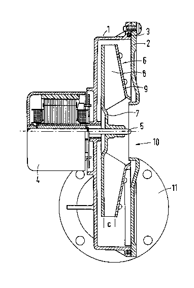
Fig. 1 is a longitudinal section of an embodiment
of the radial-flow fan in accordance with
the invention;
Fig. 2 is a side view showing the basic design of
the radial-flow fan of Fig. 1;
Fig. 3 is a front view of the impeller, and
Fig. 4 shows the basic design of the impeller
of Fig. 3.
As can be seen in Fig. 1, the casing 1 of the radial-
flow fan is closed with the cover 2. In the embodiment
shown, the casing 1 and the cover 2 are aluminum die
castings. They are screwed to-
gether at the edge, with a seal 3 inserted between them.
Flanged to the rear of the casing 1 is the drive motor
4, whose output shaft 5 extends into the casing 1. The
drive motor shown is an electronically commutated
direct-current motor. It is also possibLe to use an al-
ternating-current motor. The impeller 6 is nonpositively
and/or positively fixed to the end of the output shaft 5
projecting into the casing 1. The outlet width of the
impeller 6 is designated c. The impelLer 6 cons;sts of
the rear part 7, having the blades ~ formed integrally
thereon, and the cover 9. In the embodiment shown, the
length of the blade8 at the rear end, i.e., at the rear part
7, is greater than that at the front end, i.e., near the
R. Hopfensperger - R. Tungl 18-6

2~2~
-- 4
cover . The impeller 6 may be of metal or plastic.
In the radial-flow fan shown, the gaseous medium is
sucked in axia.ly, i.e., through an opening 10 in the
cover 2, and blown off radially (into the picture plane
of Fig. 1). The blow-off opening is a rectangular outlet
in the circular flange 11O
Fig. 2 illustrates the effective shape of the radial-
flow fan in accordance with the invention. The casing 1
has a spiral-shaped inner contour 12. Within this inner
contour, the impeller 6 with the blades 8 is arranged in
such a way that the shortest and a nearly uniform distance
between inner contour 12 and ;mpeller 6 ;s obtained between
the points A and ~. In the embod;ment shown, this distance
is equal to 6% of the impeller radius (= 65 mm), and the
dimens;ons a and b are 156 mm. The blades 8 are curved
backward, as follows from a compar;son w;th the direc-
tion of rotat;on of-the ;mpeller 6 ind;cated by the
arrow 13.
The curvature of each of the blades 8 corresponds essen-
tially to the arc of a circle. The blades are arranged
on the rear part 7 in such a way that the inlet angle ~1
has nearly the same value as the outlet angle ~2. In
the embodiment shown, the angles have a value of 47 degrees.
In radial-fLow fans of this type, the gap between the ;m-
peller 6 and the ;nner contour 12 of the cas;ng near the
blow-off open;ng 14 ;s called the "tongue reg;on",
R. Hopfensperger - R. Tungl 18-6

2~?~2~(3
- s
denoted 15. Unlike in conventional radial-fLow fans,
the tongue region in the present embodiment is wedge-
shaped.
Fig. 3 shows the ;mpeller 6 as seen from the suction side.
Through the opening 10 in the cover 2, the blades 8 on
the rear part 7 can be seen.
Fig. 4 again illustra-tes that the curvatures of the
blades 8 are arcs of circles. The centers of all these
circles are located on the circle 16. In the case of an
impeller 6 with an outside diameter of 130 mm, the dia-
meter of the circle 16 is 98 mm.
R. Hopenfensperger - R. Tungl 18-6

Representative Drawing
A single figure which represents the drawing illustrating the invention.
Administrative Status

2024-08-01:As part of the Next Generation Patents (NGP) transition, the Canadian Patents Database (CPD) now contains a more detailed Event History, which replicates the Event Log of our new back-office solution.

Please note that "Inactive:" events refers to events no longer in use in our new back-office solution.

For a clearer understanding of the status of the application/patent presented on this page, the site Disclaimer , as well as the definitions for Patent , Event History , Maintenance Fee  and Payment History  should be consulted.

Event History

Description Date
Time Limit for Reversal Expired 1994-01-18
Application Not Reinstated by Deadline 1994-01-18
Deemed Abandoned - Failure to Respond to Maintenance Fee Notice 1993-07-16
Inactive: Adhoc Request Documented 1993-07-16
Application Published (Open to Public Inspection) 1991-01-23

Abandonment History

Abandonment Date Reason Reinstatement Date
1993-07-16
Owners on Record

Note: Records showing the ownership history in alphabetical order.

Current Owners on Record
STANDARD ELEKTRIK LORENZ AKTIENGESELLSCHAFT
Past Owners on Record
REINHOLD HOPFENSPERGER
RUDOLF TUNGL
Past Owners that do not appear in the "Owners on Record" listing will appear in other documentation within the application.
Documents

To view selected files, please enter reCAPTCHA code :


To view images, click a link in the Document Description column. To download the documents, select one or more checkboxes in the first column and then click the "Download Selected in PDF format (Zip Archive)" or the "Download Selected as Single PDF" button.

List of published and non-published patent-specific documents on the CPD .

If you have any difficulty accessing content, you can call the Client Service Centre at 1-866-997-1936 or send them an e-mail at CIPO Client Service Centre.


Document
Description 
Date
(yyyy-mm-dd) 
Number of pages   Size of Image (KB) 
Drawings 1991-01-22 3 55
Abstract 1991-01-22 1 9
Claims 1991-01-22 2 37
Descriptions 1991-01-22 5 102
Representative drawing 1999-07-14 1 24
Fees 1992-07-02 1 24