Sélection de la langue

Search

Sommaire du brevet 2021288 

Énoncé de désistement de responsabilité concernant l'information provenant de tiers

Une partie des informations de ce site Web a été fournie par des sources externes. Le gouvernement du Canada n'assume aucune responsabilité concernant la précision, l'actualité ou la fiabilité des informations fournies par les sources externes. Les utilisateurs qui désirent employer cette information devraient consulter directement la source des informations. Le contenu fourni par les sources externes n'est pas assujetti aux exigences sur les langues officielles, la protection des renseignements personnels et l'accessibilité.

Disponibilité de l'Abrégé et des Revendications

L'apparition de différences dans le texte et l'image des Revendications et de l'Abrégé dépend du moment auquel le document est publié. Les textes des Revendications et de l'Abrégé sont affichés :

  • lorsque la demande peut être examinée par le public;
  • lorsque le brevet est émis (délivrance).
(12) Demande de brevet: (11) CA 2021288
(54) Titre français: DISPOSITIF DE TRANSPORT D'UN GAZ
(54) Titre anglais: DEVICE FOR CONVEYING A GASEOUS MEDIUM
Statut: Réputée abandonnée et au-delà du délai pour le rétablissement - en attente de la réponse à l’avis de communication rejetée
Données bibliographiques
(51) Classification internationale des brevets (CIB):
  • F04D 17/00 (2006.01)
(72) Inventeurs :
  • HOPFENSPERGER, REINHOLD (Allemagne)
  • TUNGL, RUDOLF (Allemagne)
(73) Titulaires :
  • STANDARD ELEKTRIK LORENZ AKTIENGESELLSCHAFT
(71) Demandeurs :
  • STANDARD ELEKTRIK LORENZ AKTIENGESELLSCHAFT (Allemagne)
(74) Agent: SMART & BIGGAR LP
(74) Co-agent:
(45) Délivré:
(22) Date de dépôt: 1990-07-16
(41) Mise à la disponibilité du public: 1991-01-23
Licence disponible: S.O.
Cédé au domaine public: S.O.
(25) Langue des documents déposés: Anglais

Traité de coopération en matière de brevets (PCT): Non

(30) Données de priorité de la demande:
Numéro de la demande Pays / territoire Date
39 24 281.1 (Allemagne) 1989-07-22

Abrégés

Abrégé anglais


Abstract
Device for Conveying a Gaseous Medium
A radial-flow fan is disclosed which is especially
suited for use in gas boilers employing ceramic area
burners. This radial-flow fan has a spiral-shaped inner
contour and a closed, backward bladed impeller. It takes
up little space and produces little noise.
(Fig. 1)

Revendications

Note : Les revendications sont présentées dans la langue officielle dans laquelle elles ont été soumises.


P 39 24 281.1
Claims
1. Device for conveying a gaseous medium in a device
having a high flow resistance,
c h a r a c t e r i z e d b y a radial-flow fan
whose casing (1) has a spiral-shaped inner contour (12)
and which has a closed impeller (6) whose blades (8)
are curved backward and whose diameter is very much
greater than its outlet width.
2. A radial-flow fan as claimed in claim 1, charac-
terized in that the diameter of the impeller (6) is
more than ten times its outlet width.
3. A radial-flow fan as claimed in claims 1 and 2, charac-
terized in that the curvature of each of the blades (8) of the im-
peller (6) corresponds essentially to the arc of a circle.
4. A radial-flow fan as claimed in claims 1 to 3,
characterized in that the blades (8) are so disposed
in the impeller (6) that their inlet angle B1 and
their outlet angle B2 have approximately the same
value.

- 2 -
5. A radial-flow fan as claimed in claims 1 to 4, charac-
terized in that the inlet and outlet angles preferably
have a value between 45 and 50 degrees.
6. A radial-flow fan as claimed in claims 1 to 5, charac-
terized in that the gap between the impeller (6) and
the inner contour (12) of the casing, i.e., the tongue
region (15), is wedge-shaped.
7. A radial-flow fan as claimed in claims 1 to 6, charac-
terized in that the point of the shortest distance be-
tween the impeller (6) and the inner contour (12) of
the casing (1) is shifted from the tongue region (15)
in the direction of rotation of the impeller (6).
8. A radial-flow fan as claimed in claims 1 to 7,
characterized in that the shortest distance between the
circumference of the impeller (6) and the inner contour
(12) of the casing (1) is equal to between 4 and 8% of
the impeller radius.
9. A radial-flow fan as claimed in claims 1 to 8,
characterized in that the impeller is driven by a
direct-current motor (4).

Description

Note : Les descriptions sont présentées dans la langue officielle dans laquelle elles ont été soumises.

2 ~ ~
P 39 24 281.1
3escription
Device for Conveying a Gaseous Medium
Thepresent invention re(a~es to a device for conveying
a gaseous medium in a device having a high flow resis-
tance.
The device with a high flow resistance may be, for example,
a ceramic area burner as has lately been used in gas
boilers~ Such gas boilers with ceramic area burners are
known (journal "HLH, Heizung, Luftung/Klima, Haustechnik;
Zeitschrift des Vereins deutscher Ingenieure fur tech-
nische Geb3udeausrustung", June 1989, page 308). They
have a relatively high flow resistance which is of the
order of Z00 pascals and more. The medium to be conveyed
may be either air or a combustible gas mixture.
Accordingly~ the technical problem to be solved by the
invention is to provide a device for conveying a gaseous
medium in a device having a high flow resistance wherein~
on the one hand, the conveyed medium has a relatively high
ZPL-Bnd Ke/Lo R. Hopfensperger - R. Tungl 18-6
,

2~
- z
back pressure and which, on the other hand, has a steep
pressure/volume characteristic, i.e., large changes in
pressure are to be accompanied by only smalL changes
in volume rate of flow. The high back pressure is to be
about 400 to 450 pascals, and the volume rate of flow
is to be ab~ut 7 to 10 l/s if the gaseous medium has a
density of p = 1.2 kg/m3. As the apparatus in which the
device is used must not take up too much space, the base
occupied by the device (height multiplied by breadth)
must not exceed a given size, e.g., 180 by 180 mm.
In addition, the self-noise of the device should not
exceed the self-noise of prior art devices for conveying
a gaseous medium.
According to the invention, this technical problem is
solved by a radial-flow fan whose casing has a spiral-
shaped inner contour and which has a closed impeller
whose blades are curved backward and whose diameter is
very much greater than its outlet width~
In the radial-flow fan according to the invention, one
version of which is smaller than 170 mm2 (he;ght multi-
plied by breadth), the conveyed gaseous medium has a
pressure of 415 pascals and a volume rate of flow of
6.9 lts at the intended working point. The speed of the
impeller was about 3800 revolutions per minute.
Further advantageous features of the inuention are de~ined
in claims 2 to 9. The invention will now be explained with
R. Hopfensperger - R. Tungl 18-6

~ 3 ~ 2~J~2~8
reference to the accompanying drawings, in which:
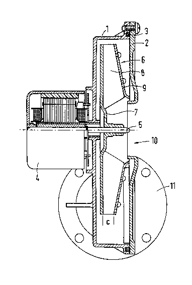
Fig. 1 is a longitudinal section of an embodiment
of the radial-flow fan in accordance with
the invention;
Fig. 2 is a side view showing the basic design of
the radial-flow fan of Fig. 1;
Fig. 3 is a front view of the impeller, and
Fig. 4 shows the basic design of the impeller
of Fig. 3.
As can be seen in Fig. 1, the casing 1 of the radial-
flow fan is closed with the cover 2. In the embodiment
shown, the casing 1 and the cover 2 are aluminum die
castings. They are screwed to-
gether at the edge, with a seal 3 inserted between them.
Flanged to the rear of the casing 1 is the drive motor
4, whose output shaft 5 extends into the casing 1. The
drive motor shown is an electronically commutated
direct-current motor. It is also possibLe to use an al-
ternating-current motor. The impeller 6 is nonpositively
and/or positively fixed to the end of the output shaft 5
projecting into the casing 1. The outlet width of the
impeller 6 is designated c. The impelLer 6 cons;sts of
the rear part 7, having the blades ~ formed integrally
thereon, and the cover 9. In the embodiment shown, the
length of the blade8 at the rear end, i.e., at the rear part
7, is greater than that at the front end, i.e., near the
R. Hopfensperger - R. Tungl 18-6

2~2~
-- 4
cover . The impeller 6 may be of metal or plastic.
In the radial-flow fan shown, the gaseous medium is
sucked in axia.ly, i.e., through an opening 10 in the
cover 2, and blown off radially (into the picture plane
of Fig. 1). The blow-off opening is a rectangular outlet
in the circular flange 11O
Fig. 2 illustrates the effective shape of the radial-
flow fan in accordance with the invention. The casing 1
has a spiral-shaped inner contour 12. Within this inner
contour, the impeller 6 with the blades 8 is arranged in
such a way that the shortest and a nearly uniform distance
between inner contour 12 and ;mpeller 6 ;s obtained between
the points A and ~. In the embod;ment shown, this distance
is equal to 6% of the impeller radius (= 65 mm), and the
dimens;ons a and b are 156 mm. The blades 8 are curved
backward, as follows from a compar;son w;th the direc-
tion of rotat;on of-the ;mpeller 6 ind;cated by the
arrow 13.
The curvature of each of the blades 8 corresponds essen-
tially to the arc of a circle. The blades are arranged
on the rear part 7 in such a way that the inlet angle ~1
has nearly the same value as the outlet angle ~2. In
the embodiment shown, the angles have a value of 47 degrees.
In radial-fLow fans of this type, the gap between the ;m-
peller 6 and the ;nner contour 12 of the cas;ng near the
blow-off open;ng 14 ;s called the "tongue reg;on",
R. Hopfensperger - R. Tungl 18-6

2~?~2~(3
- s
denoted 15. Unlike in conventional radial-fLow fans,
the tongue region in the present embodiment is wedge-
shaped.
Fig. 3 shows the ;mpeller 6 as seen from the suction side.
Through the opening 10 in the cover 2, the blades 8 on
the rear part 7 can be seen.
Fig. 4 again illustra-tes that the curvatures of the
blades 8 are arcs of circles. The centers of all these
circles are located on the circle 16. In the case of an
impeller 6 with an outside diameter of 130 mm, the dia-
meter of the circle 16 is 98 mm.
R. Hopenfensperger - R. Tungl 18-6

Dessin représentatif
Une figure unique qui représente un dessin illustrant l'invention.
États administratifs

2024-08-01 : Dans le cadre de la transition vers les Brevets de nouvelle génération (BNG), la base de données sur les brevets canadiens (BDBC) contient désormais un Historique d'événement plus détaillé, qui reproduit le Journal des événements de notre nouvelle solution interne.

Veuillez noter que les événements débutant par « Inactive : » se réfèrent à des événements qui ne sont plus utilisés dans notre nouvelle solution interne.

Pour une meilleure compréhension de l'état de la demande ou brevet qui figure sur cette page, la rubrique Mise en garde , et les descriptions de Brevet , Historique d'événement , Taxes périodiques et Historique des paiements devraient être consultées.

Historique d'événement

Description Date
Le délai pour l'annulation est expiré 1994-01-18
Demande non rétablie avant l'échéance 1994-01-18
Réputée abandonnée - omission de répondre à un avis sur les taxes pour le maintien en état 1993-07-16
Inactive : Demande ad hoc documentée 1993-07-16
Demande publiée (accessible au public) 1991-01-23

Historique d'abandonnement

Date d'abandonnement Raison Date de rétablissement
1993-07-16
Titulaires au dossier

Les titulaires actuels et antérieures au dossier sont affichés en ordre alphabétique.

Titulaires actuels au dossier
STANDARD ELEKTRIK LORENZ AKTIENGESELLSCHAFT
Titulaires antérieures au dossier
REINHOLD HOPFENSPERGER
RUDOLF TUNGL
Les propriétaires antérieurs qui ne figurent pas dans la liste des « Propriétaires au dossier » apparaîtront dans d'autres documents au dossier.
Documents

Pour visionner les fichiers sélectionnés, entrer le code reCAPTCHA :


Pour visualiser une image, cliquer sur un lien dans la colonne description du document. Pour télécharger l'image (les images), cliquer l'une ou plusieurs cases à cocher dans la première colonne et ensuite cliquer sur le bouton "Télécharger sélection en format PDF (archive Zip)" ou le bouton "Télécharger sélection (en un fichier PDF fusionné)".

Liste des documents de brevet publiés et non publiés sur la BDBC .

Si vous avez des difficultés à accéder au contenu, veuillez communiquer avec le Centre de services à la clientèle au 1-866-997-1936, ou envoyer un courriel au Centre de service à la clientèle de l'OPIC.


Description du
Document 
Date
(aaaa-mm-jj) 
Nombre de pages   Taille de l'image (Ko) 
Dessins 1991-01-22 3 55
Abrégé 1991-01-22 1 9
Revendications 1991-01-22 2 37
Description 1991-01-22 5 102
Dessin représentatif 1999-07-14 1 24
Taxes 1992-07-02 1 24