Language selection

Search

Patent 2021924 Summary

Third-party information liability

Some of the information on this Web page has been provided by external sources. The Government of Canada is not responsible for the accuracy, reliability or currency of the information supplied by external sources. Users wishing to rely upon this information should consult directly with the source of the information. Content provided by external sources is not subject to official languages, privacy and accessibility requirements.

Claims and Abstract availability

Any discrepancies in the text and image of the Claims and Abstract are due to differing posting times. Text of the Claims and Abstract are posted:

  • At the time the application is open to public inspection;
  • At the time of issue of the patent (grant).
(12) Patent: (11) CA 2021924
(54) English Title: ELECTRICAL PROBE
(54) French Title: SONDE ELECTRIQUE
Status: Expired and beyond the Period of Reversal
Bibliographic Data
(51) International Patent Classification (IPC):
  • G1R 1/06 (2006.01)
  • G1R 19/165 (2006.01)
(72) Inventors :
  • KALISHMAN, CALVIN (United States of America)
(73) Owners :
  • CALVIN KALISHMAN
(71) Applicants :
(74) Agent: SWABEY OGILVY RENAULT
(74) Associate agent:
(45) Issued: 1994-09-20
(22) Filed Date: 1990-07-25
(41) Open to Public Inspection: 1991-05-23
Examination requested: 1993-04-23
Availability of licence: N/A
Dedicated to the Public: N/A
(25) Language of filing: English

Patent Cooperation Treaty (PCT): No

(30) Application Priority Data:
Application No. Country/Territory Date
07/440,989 (United States of America) 1989-11-22

Abstracts

English Abstract


A hand-held probing device is adapted for use in testing
the existence and amount of electrical potential in an
automobile engine block or other object under investigation.
The device has a specially formed housing from which extends a
probe and a ground lead at opposite ends. The housing also
includes a voltmeter and an electric bulb connected in parallel
between the probe and ground lead. The housing also includes a
switch which enables the device to be operated while held in
one hand thus enabling the other of the user's hand to be free
and usable for other functions.


Claims

Note: Claims are shown in the official language in which they were submitted.


The embodiments of the invention in which an
exclusive property or privilege is claimed are defined
as follows:
1. An elongated electrical probe comprising:
an elongated hollow handle;
a hollow housing secured to the forward end
of said handle;
an electrically conductive housing secured
to and extending forwardly from said housing, the rear
end of said probe being disposed within said housing;
said handle and said housing having
cylindrical cross-sectional configurations, said
housing, handle and probe being arranged on a common
longitudinal axis, said housing being of a larger
cross-sectional diameter than that of said handle;
a voltmeter mounted within said housing and
having a scale thereof, said housing including a window
to enable said scale to be read through;
a lamp means mounted to the rear of said
handle;
said lamp means includes a lamp;
said lamp means including a socket secured
to the rear end of said handle and opening rearwardly
therefrom;
wire means connecting said rear end of said
probe to said voltmeter and said lamp means, said
voltmeter and said lamp means being connected in
parallel;
said probe has a first concentric fastener
disposed on the forward side thereof, said first
concentric fastener contacting said housing for
securing said probe to said housing;
said probe having a set of concentric
fasteners axially spaced apart on the rear side
thereof, said wire means sandwiched therebetween for
physically securing and electrically connecting said
probe to said wire means;
- 7 -

said wire means including an isolated wire
having a segment thereof that is exposed for contact
with the lamp socket;
a ground lead wire connected to said lamp,
the free end of said ground wire including a ground
clip attached thereto;
a normally open switch secured to a side
wall of said housing at a relatively close position to
said handle and being operable for outside of said
housing, said switch being connected in series between
said rear end of said probe and said voltmeter for
enabling closing of the circuit between said probe and
said voltmeter for enabling detection of a voltage;
means securing said normally open switch to
said housing at a position within finger distance of
the end of said handle that attaches to said housing;
a transparent plastic cap connectable to the
rear end of said handle and defining a lamp chamber to
protect said lamp and enable operation of said lamp to
be viewed, said cap having a hole therein to enable
said ground wire to pass rearward therethrough;
two inwardly directed flanges defining
shoulders located within said hollow handle in the rear
side thereof;
said shoulders for receiving said socket and
supporting said plastic cap; and
said handle being at least as long as the
combined length of said housing and said electrically
conductive probe.
- 8 -

Description

Note: Descriptions are shown in the official language in which they were submitted.


- 2021324
,.
M0330/7002
DMDJdpv
11-7-89
9862d
ELECTRICAL PROBE
BACKGROUND OF THE INVENTION
The present invention relates to electrical testing probes
and pertains, m~re particularly, to an improved probe which
enables the user to detect easily the existence of any
electrical potential, particularly for automotive applications
in testing electrical components of an automobile.
SUMMARY OF THE INVENTION
Although the invention is intended for use primarily to
determine the existence of an electrical potential in an
automotive application, it may be used similarly to test the
existence of a voltage or potential in other applications. The
probe includes a non-metallic housing, preferably plastic,
which is adapted to be held easily in and operated by one
hand. Unlike other probes employed for this purpose,
particularly in automotive maintenance, all of the necessary
elements are contained within th~ hand-held probing device
itself. There is no need to connect leads from the probe to
external measuring or detecting equipment. The user can
determine the existence and amount of electrical potential
without referring to the remote instruments.

20~192~
.
The device includes an elongated probe at one end and a
ground clip at the other end. The device has an enlarged
housing at its forward probe end which contains a voltmeter and
a'normally open switch connected in series. Extendlng
rearwardly from the enlarged housing is a narrowed handle
having a lamp at the rear end, the lamp being exposed through a
clear plastic cover at the end of the handle. The lamp is
connected in parallel with the switch and volt meter by means
of wires passing through the housing and the handle. When
using the device to test the potential in an automobile engine,
the ground clip may be attached to the chassis of the vehicle
and the probe is contacted with the engine block or other
elements under investigation. The switch then is closed. If
any electrical potential exists between the two points being
tested, namely the probe and the ground clip, then the electric
lamp will light and the voltmeter will read the voltage level.
The device is operated with one hand which frees the user's
other hand for other functions.
~ It is among the primary objects of the invention to
provide a simple probe to enable one to detect the exis.ence of
an electrical potential in a member such as an automobile
engine block.

2~2:~924
Another object of the invention is to provide a probe
which may be gripped and operated easily by one hand and which
contains both an indicator light and a voltmeter which enables
t~e voltage to be detected without reference to any external
measuring or testing devices.
DESCRIPTION OF THE DRAWINGS
These and other objects and advantages of the invention
will be understood more fully from the following detailed
description thereof with reference to the accompanying drawing
which shows the device in longitudinal section.
DESCRIPTION OF THE PREFERRED EMBODIMENT
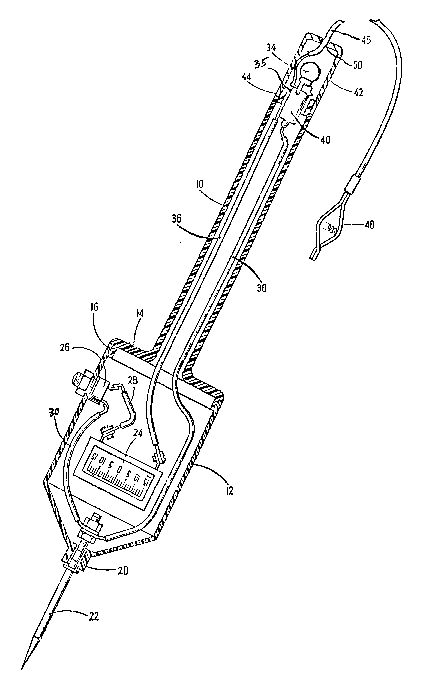
As shown in the drawing, the device is of elongated
configuration having a slim easily gripped handle 10 at its
rear and an enlarged cylindrical housing 12 at its forward
end. The handle 10 and housing 12 are formed from an
insulative material such as an appropriate plastic. In the
preferred construction, the forward end of the handle 10
includes an enlarged flange 14 having a rim 16 formed forwardly
about is periphery. The rim 16 preferably engages the rear end
of the housing 12 in a snap-fit to enable these parts to be
detachably secured to each other. The forward end of the
housing 12 has an opening 20 formed therein through which a
conductive probe 22 extends forwardly. The rear end of the
probe 22 is disposed within the housing and is connected to a

20-2I92A
voltmeter 24 through a switch 26 by the wireS 28, 30
respectively. Switch 26 is secured to the housing 12 and is
e~posed through the housing so that it may be operated
conveniently by the user's finger or thumb. The switch 26 is
of normally open configuration and requires actuation when the
probe is being used. The voltmeter 24 is securely mounted
within the housing. The housing 12 includes a clear plastic
window to expose the voltmeter scale and enable it to be read
easily. The voltmeter is connected in parallel with a
conventional resistance lamp 34 located at the rearward end of
the handle 10 by means of wires 36, 38. The rear end of the
handle 10 includes a bayonet type socket 40 to which the wires
36, 38 are connected. The socket may be press-fitted into the
handle and receives the lamp 34. This entire assembly is
enclosed in a clear plastic cover 42 which may be threaded on
to a reduced portion 44 at the end of the handle. A ground
lead 46 is connected to one of the socket terminals and has a
clip 48 at its outer end. The ground lead 46-passes through a
hole 50 formed in the end of the cover 42.
The device is very simple to use in that the ground clip
need only be attached to a suita-ble ground or reference voltage
member such as an automobile chassis. With the device held in
one hand, the probe is brought firmly into contact with the
electrical component being tested which may be an engine block

2021924
and the switch is depressed by the user's finger or thumb. The
existence of a potential will be indicated immediately by
lighting of the lamp 34. The user may determine the magnitude
of the potential simply by reading the exposed voltmeter scale
on the side of the housing 12. There is no need to refer to or
manipulate any external electrical apparatus and the test may
be completed s~ply and rapidly. Because the complete device
is self-contained and is easily operable it may be used to test
the existence and magnitude of electric potentials in a variety
of adjacent-locations.
It is furthermore noted, with regard to the socket 40,
that the wire 36, 46, although covered along a substantial
portion of its length has the actual metal wire 35 exposed
along a segment thereof. This is then in contact with the
socket 40 to complete the circuit. The other wire 38 has its
conductor connected to the center electrode of the socket
associated with the center electrode of-the lamp 34.
In the drawing, the voltmeter 24 is illustrated having a
scale primarily adapted for automotive applications. However,
this scale may also be in different voltage ranges such as one
in a range of 0 to 150 volts. This could be used for household
applications. Also, the lamp 34 may be replaced by some type
of a neon illuminating means.

2021 ~
It should be understood that the foregoing description of
the invention is intended merely to be illustrative thereof and
that other embodiments and modifications may be apparent to
t~ose skilled in the art-without departing from its spirit.

Representative Drawing
A single figure which represents the drawing illustrating the invention.
Administrative Status

2024-08-01:As part of the Next Generation Patents (NGP) transition, the Canadian Patents Database (CPD) now contains a more detailed Event History, which replicates the Event Log of our new back-office solution.

Please note that "Inactive:" events refers to events no longer in use in our new back-office solution.

For a clearer understanding of the status of the application/patent presented on this page, the site Disclaimer , as well as the definitions for Patent , Event History , Maintenance Fee  and Payment History  should be consulted.

Event History

Description Date
Inactive: IPC from MCD 2006-03-11
Time Limit for Reversal Expired 2000-07-25
Letter Sent 1999-07-26
Grant by Issuance 1994-09-20
Request for Examination Requirements Determined Compliant 1993-04-23
All Requirements for Examination Determined Compliant 1993-04-23
Application Published (Open to Public Inspection) 1991-05-23

Abandonment History

There is no abandonment history.

Fee History

Fee Type Anniversary Year Due Date Paid Date
MF (patent, 7th anniv.) - small 1997-07-25 1997-06-16
MF (patent, 8th anniv.) - small 1998-07-27 1998-06-15
Owners on Record

Note: Records showing the ownership history in alphabetical order.

Current Owners on Record
CALVIN KALISHMAN
Past Owners on Record
None
Past Owners that do not appear in the "Owners on Record" listing will appear in other documentation within the application.
Documents

To view selected files, please enter reCAPTCHA code :


To view images, click a link in the Document Description column (Temporarily unavailable). To download the documents, select one or more checkboxes in the first column and then click the "Download Selected in PDF format (Zip Archive)" or the "Download Selected as Single PDF" button.

List of published and non-published patent-specific documents on the CPD .

If you have any difficulty accessing content, you can call the Client Service Centre at 1-866-997-1936 or send them an e-mail at CIPO Client Service Centre.

({010=All Documents, 020=As Filed, 030=As Open to Public Inspection, 040=At Issuance, 050=Examination, 060=Incoming Correspondence, 070=Miscellaneous, 080=Outgoing Correspondence, 090=Payment})


Document
Description 
Date
(yyyy-mm-dd) 
Number of pages   Size of Image (KB) 
Abstract 1994-09-19 1 17
Description 1994-09-19 6 177
Claims 1994-09-19 2 74
Drawings 1994-09-19 1 24
Abstract 1994-04-15 1 16
Description 1994-04-15 6 161
Claims 1994-04-15 2 50
Drawings 1994-04-15 1 25
Representative drawing 1999-07-14 1 21
Maintenance Fee Notice 1999-08-22 1 179
Fees 1996-06-11 1 50
Fees 1995-06-13 1 57
Fees 1994-06-29 1 78
Fees 1993-06-17 1 54
Fees 1992-06-17 1 59
Prosecution correspondence 1993-04-22 2 47
Courtesy - Office Letter 1993-05-11 1 32
PCT Correspondence 1994-07-05 1 40
Prosecution correspondence 1993-11-29 2 55
Examiner Requisition 1993-08-29 2 80
Prosecution correspondence 1993-08-08 1 51