Sélection de la langue

Search

Sommaire du brevet 2021924 

Énoncé de désistement de responsabilité concernant l'information provenant de tiers

Une partie des informations de ce site Web a été fournie par des sources externes. Le gouvernement du Canada n'assume aucune responsabilité concernant la précision, l'actualité ou la fiabilité des informations fournies par les sources externes. Les utilisateurs qui désirent employer cette information devraient consulter directement la source des informations. Le contenu fourni par les sources externes n'est pas assujetti aux exigences sur les langues officielles, la protection des renseignements personnels et l'accessibilité.

Disponibilité de l'Abrégé et des Revendications

L'apparition de différences dans le texte et l'image des Revendications et de l'Abrégé dépend du moment auquel le document est publié. Les textes des Revendications et de l'Abrégé sont affichés :

  • lorsque la demande peut être examinée par le public;
  • lorsque le brevet est émis (délivrance).
(12) Brevet: (11) CA 2021924
(54) Titre français: SONDE ELECTRIQUE
(54) Titre anglais: ELECTRICAL PROBE
Statut: Périmé et au-delà du délai pour l’annulation
Données bibliographiques
(51) Classification internationale des brevets (CIB):
  • G1R 1/06 (2006.01)
  • G1R 19/165 (2006.01)
(72) Inventeurs :
  • KALISHMAN, CALVIN (Etats-Unis d'Amérique)
(73) Titulaires :
  • CALVIN KALISHMAN
(71) Demandeurs :
(74) Agent: SWABEY OGILVY RENAULT
(74) Co-agent:
(45) Délivré: 1994-09-20
(22) Date de dépôt: 1990-07-25
(41) Mise à la disponibilité du public: 1991-05-23
Requête d'examen: 1993-04-23
Licence disponible: S.O.
Cédé au domaine public: S.O.
(25) Langue des documents déposés: Anglais

Traité de coopération en matière de brevets (PCT): Non

(30) Données de priorité de la demande:
Numéro de la demande Pays / territoire Date
07/440,989 (Etats-Unis d'Amérique) 1989-11-22

Abrégés

Abrégé anglais


A hand-held probing device is adapted for use in testing
the existence and amount of electrical potential in an
automobile engine block or other object under investigation.
The device has a specially formed housing from which extends a
probe and a ground lead at opposite ends. The housing also
includes a voltmeter and an electric bulb connected in parallel
between the probe and ground lead. The housing also includes a
switch which enables the device to be operated while held in
one hand thus enabling the other of the user's hand to be free
and usable for other functions.

Revendications

Note : Les revendications sont présentées dans la langue officielle dans laquelle elles ont été soumises.


The embodiments of the invention in which an
exclusive property or privilege is claimed are defined
as follows:
1. An elongated electrical probe comprising:
an elongated hollow handle;
a hollow housing secured to the forward end
of said handle;
an electrically conductive housing secured
to and extending forwardly from said housing, the rear
end of said probe being disposed within said housing;
said handle and said housing having
cylindrical cross-sectional configurations, said
housing, handle and probe being arranged on a common
longitudinal axis, said housing being of a larger
cross-sectional diameter than that of said handle;
a voltmeter mounted within said housing and
having a scale thereof, said housing including a window
to enable said scale to be read through;
a lamp means mounted to the rear of said
handle;
said lamp means includes a lamp;
said lamp means including a socket secured
to the rear end of said handle and opening rearwardly
therefrom;
wire means connecting said rear end of said
probe to said voltmeter and said lamp means, said
voltmeter and said lamp means being connected in
parallel;
said probe has a first concentric fastener
disposed on the forward side thereof, said first
concentric fastener contacting said housing for
securing said probe to said housing;
said probe having a set of concentric
fasteners axially spaced apart on the rear side
thereof, said wire means sandwiched therebetween for
physically securing and electrically connecting said
probe to said wire means;
- 7 -

said wire means including an isolated wire
having a segment thereof that is exposed for contact
with the lamp socket;
a ground lead wire connected to said lamp,
the free end of said ground wire including a ground
clip attached thereto;
a normally open switch secured to a side
wall of said housing at a relatively close position to
said handle and being operable for outside of said
housing, said switch being connected in series between
said rear end of said probe and said voltmeter for
enabling closing of the circuit between said probe and
said voltmeter for enabling detection of a voltage;
means securing said normally open switch to
said housing at a position within finger distance of
the end of said handle that attaches to said housing;
a transparent plastic cap connectable to the
rear end of said handle and defining a lamp chamber to
protect said lamp and enable operation of said lamp to
be viewed, said cap having a hole therein to enable
said ground wire to pass rearward therethrough;
two inwardly directed flanges defining
shoulders located within said hollow handle in the rear
side thereof;
said shoulders for receiving said socket and
supporting said plastic cap; and
said handle being at least as long as the
combined length of said housing and said electrically
conductive probe.
- 8 -

Description

Note : Les descriptions sont présentées dans la langue officielle dans laquelle elles ont été soumises.

- 2021324
,.
M0330/7002
DMDJdpv
11-7-89
9862d
ELECTRICAL PROBE
BACKGROUND OF THE INVENTION
The present invention relates to electrical testing probes
and pertains, m~re particularly, to an improved probe which
enables the user to detect easily the existence of any
electrical potential, particularly for automotive applications
in testing electrical components of an automobile.
SUMMARY OF THE INVENTION
Although the invention is intended for use primarily to
determine the existence of an electrical potential in an
automotive application, it may be used similarly to test the
existence of a voltage or potential in other applications. The
probe includes a non-metallic housing, preferably plastic,
which is adapted to be held easily in and operated by one
hand. Unlike other probes employed for this purpose,
particularly in automotive maintenance, all of the necessary
elements are contained within th~ hand-held probing device
itself. There is no need to connect leads from the probe to
external measuring or detecting equipment. The user can
determine the existence and amount of electrical potential
without referring to the remote instruments.

20~192~
.
The device includes an elongated probe at one end and a
ground clip at the other end. The device has an enlarged
housing at its forward probe end which contains a voltmeter and
a'normally open switch connected in series. Extendlng
rearwardly from the enlarged housing is a narrowed handle
having a lamp at the rear end, the lamp being exposed through a
clear plastic cover at the end of the handle. The lamp is
connected in parallel with the switch and volt meter by means
of wires passing through the housing and the handle. When
using the device to test the potential in an automobile engine,
the ground clip may be attached to the chassis of the vehicle
and the probe is contacted with the engine block or other
elements under investigation. The switch then is closed. If
any electrical potential exists between the two points being
tested, namely the probe and the ground clip, then the electric
lamp will light and the voltmeter will read the voltage level.
The device is operated with one hand which frees the user's
other hand for other functions.
~ It is among the primary objects of the invention to
provide a simple probe to enable one to detect the exis.ence of
an electrical potential in a member such as an automobile
engine block.

2~2:~924
Another object of the invention is to provide a probe
which may be gripped and operated easily by one hand and which
contains both an indicator light and a voltmeter which enables
t~e voltage to be detected without reference to any external
measuring or testing devices.
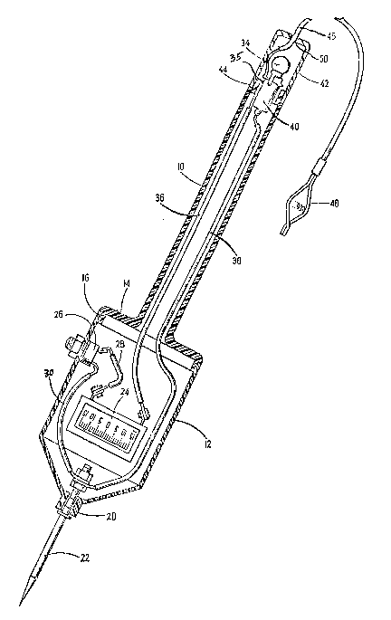
DESCRIPTION OF THE DRAWINGS
These and other objects and advantages of the invention
will be understood more fully from the following detailed
description thereof with reference to the accompanying drawing
which shows the device in longitudinal section.
DESCRIPTION OF THE PREFERRED EMBODIMENT
As shown in the drawing, the device is of elongated
configuration having a slim easily gripped handle 10 at its
rear and an enlarged cylindrical housing 12 at its forward
end. The handle 10 and housing 12 are formed from an
insulative material such as an appropriate plastic. In the
preferred construction, the forward end of the handle 10
includes an enlarged flange 14 having a rim 16 formed forwardly
about is periphery. The rim 16 preferably engages the rear end
of the housing 12 in a snap-fit to enable these parts to be
detachably secured to each other. The forward end of the
housing 12 has an opening 20 formed therein through which a
conductive probe 22 extends forwardly. The rear end of the
probe 22 is disposed within the housing and is connected to a

20-2I92A
voltmeter 24 through a switch 26 by the wireS 28, 30
respectively. Switch 26 is secured to the housing 12 and is
e~posed through the housing so that it may be operated
conveniently by the user's finger or thumb. The switch 26 is
of normally open configuration and requires actuation when the
probe is being used. The voltmeter 24 is securely mounted
within the housing. The housing 12 includes a clear plastic
window to expose the voltmeter scale and enable it to be read
easily. The voltmeter is connected in parallel with a
conventional resistance lamp 34 located at the rearward end of
the handle 10 by means of wires 36, 38. The rear end of the
handle 10 includes a bayonet type socket 40 to which the wires
36, 38 are connected. The socket may be press-fitted into the
handle and receives the lamp 34. This entire assembly is
enclosed in a clear plastic cover 42 which may be threaded on
to a reduced portion 44 at the end of the handle. A ground
lead 46 is connected to one of the socket terminals and has a
clip 48 at its outer end. The ground lead 46-passes through a
hole 50 formed in the end of the cover 42.
The device is very simple to use in that the ground clip
need only be attached to a suita-ble ground or reference voltage
member such as an automobile chassis. With the device held in
one hand, the probe is brought firmly into contact with the
electrical component being tested which may be an engine block

2021924
and the switch is depressed by the user's finger or thumb. The
existence of a potential will be indicated immediately by
lighting of the lamp 34. The user may determine the magnitude
of the potential simply by reading the exposed voltmeter scale
on the side of the housing 12. There is no need to refer to or
manipulate any external electrical apparatus and the test may
be completed s~ply and rapidly. Because the complete device
is self-contained and is easily operable it may be used to test
the existence and magnitude of electric potentials in a variety
of adjacent-locations.
It is furthermore noted, with regard to the socket 40,
that the wire 36, 46, although covered along a substantial
portion of its length has the actual metal wire 35 exposed
along a segment thereof. This is then in contact with the
socket 40 to complete the circuit. The other wire 38 has its
conductor connected to the center electrode of the socket
associated with the center electrode of-the lamp 34.
In the drawing, the voltmeter 24 is illustrated having a
scale primarily adapted for automotive applications. However,
this scale may also be in different voltage ranges such as one
in a range of 0 to 150 volts. This could be used for household
applications. Also, the lamp 34 may be replaced by some type
of a neon illuminating means.

2021 ~
It should be understood that the foregoing description of
the invention is intended merely to be illustrative thereof and
that other embodiments and modifications may be apparent to
t~ose skilled in the art-without departing from its spirit.

Dessin représentatif
Une figure unique qui représente un dessin illustrant l'invention.
États administratifs

2024-08-01 : Dans le cadre de la transition vers les Brevets de nouvelle génération (BNG), la base de données sur les brevets canadiens (BDBC) contient désormais un Historique d'événement plus détaillé, qui reproduit le Journal des événements de notre nouvelle solution interne.

Veuillez noter que les événements débutant par « Inactive : » se réfèrent à des événements qui ne sont plus utilisés dans notre nouvelle solution interne.

Pour une meilleure compréhension de l'état de la demande ou brevet qui figure sur cette page, la rubrique Mise en garde , et les descriptions de Brevet , Historique d'événement , Taxes périodiques et Historique des paiements devraient être consultées.

Historique d'événement

Description Date
Inactive : CIB de MCD 2006-03-11
Le délai pour l'annulation est expiré 2000-07-25
Lettre envoyée 1999-07-26
Accordé par délivrance 1994-09-20
Exigences pour une requête d'examen - jugée conforme 1993-04-23
Toutes les exigences pour l'examen - jugée conforme 1993-04-23
Demande publiée (accessible au public) 1991-05-23

Historique d'abandonnement

Il n'y a pas d'historique d'abandonnement

Historique des taxes

Type de taxes Anniversaire Échéance Date payée
TM (brevet, 7e anniv.) - petite 1997-07-25 1997-06-16
TM (brevet, 8e anniv.) - petite 1998-07-27 1998-06-15
Titulaires au dossier

Les titulaires actuels et antérieures au dossier sont affichés en ordre alphabétique.

Titulaires actuels au dossier
CALVIN KALISHMAN
Titulaires antérieures au dossier
S.O.
Les propriétaires antérieurs qui ne figurent pas dans la liste des « Propriétaires au dossier » apparaîtront dans d'autres documents au dossier.
Documents

Pour visionner les fichiers sélectionnés, entrer le code reCAPTCHA :


Pour visualiser une image, cliquer sur un lien dans la colonne description du document (Temporairement non-disponible). Pour télécharger l'image (les images), cliquer l'une ou plusieurs cases à cocher dans la première colonne et ensuite cliquer sur le bouton "Télécharger sélection en format PDF (archive Zip)" ou le bouton "Télécharger sélection (en un fichier PDF fusionné)".

Liste des documents de brevet publiés et non publiés sur la BDBC .

Si vous avez des difficultés à accéder au contenu, veuillez communiquer avec le Centre de services à la clientèle au 1-866-997-1936, ou envoyer un courriel au Centre de service à la clientèle de l'OPIC.

({010=Tous les documents, 020=Au moment du dépôt, 030=Au moment de la mise à la disponibilité du public, 040=À la délivrance, 050=Examen, 060=Correspondance reçue, 070=Divers, 080=Correspondance envoyée, 090=Paiement})


Description du
Document 
Date
(aaaa-mm-jj) 
Nombre de pages   Taille de l'image (Ko) 
Abrégé 1994-09-19 1 17
Description 1994-09-19 6 177
Revendications 1994-09-19 2 74
Dessins 1994-09-19 1 24
Abrégé 1994-04-15 1 16
Description 1994-04-15 6 161
Revendications 1994-04-15 2 50
Dessins 1994-04-15 1 25
Dessin représentatif 1999-07-14 1 21
Avis concernant la taxe de maintien 1999-08-22 1 179
Taxes 1996-06-11 1 50
Taxes 1995-06-13 1 57
Taxes 1994-06-29 1 78
Taxes 1993-06-17 1 54
Taxes 1992-06-17 1 59
Correspondance de la poursuite 1993-04-22 2 47
Courtoisie - Lettre du bureau 1993-05-11 1 32
Correspondance reliée au PCT 1994-07-05 1 40
Correspondance de la poursuite 1993-11-29 2 55
Demande de l'examinateur 1993-08-29 2 80
Correspondance de la poursuite 1993-08-08 1 51