Note: Descriptions are shown in the official language in which they were submitted.
D-4505
ENGINE VALVE COVER GASKET DdITH ELECTRICAL BRIDGE
BACKGROUND OF THE INVENTION
The present invention relates to a gasket assembly
incorporating structure which provides an electrical bridge
or feedthrough through which electrical signals may be
passed and, more specifically, to a gasket assembly of the
type used to seal the oily environment within a valve cover
on an engine cylinder head comprising a nonconductive gasket
integrally incorporating an electrical conductor by means of
which engine control circuitry, which is disposed externally
of the valve cover, can be electrically coupled to devices,
such as fuel injectors and glow plugs disposed within the
valve cover without jeopardizing the integrity of the seal
or the continuity and insulation of the electrical circuits.
THE PRIOR ART
Heretofore, electrical communication between devices,
such as electrically Controlled fuel injectors or glow
plugs, disposed within an engine valve cover and their
externally located control circuitry has been provided by
creating holes in the valve cover to pass the wire
therethrough and the provision of complex sealing components
disposed about the holes to provide an oil tight seal
thereat as shown, for example, in Figure 1. Tn this regard,
the engine art has progressed, primarily due to
environmental considerations, from a time wherein a simile
grommet might have been used to seal a single wise to
substantially more complicated strudtures to maintain
enhanced sealing integrity of multiple circuits: Tn
additions to their cost, these structures result not only'in
a more costly, time consuming assembly process but may also
increase the difficulty of accessing the interior of the
valve cover for maintenance and repair.
SUP9P~lARY OF THE INVENTIOI~7
Accordingly, it is a primary object of the invention
described and claimed herein to provide an engine valve
cover gasket with an inexpensive and easily assemlaled
electrical bridge to carry signals from outside the valve
cover to circuit components, ,such as electrically controlled
fuel injectors and glow plugs, located within the valve
1
electrical bridge to carry signals from outside the valve
cover to circuit components, such as electrically controlled
fuel injectors and glow plugs, located within the valve
cover.
According to the invention, there is provided a plastic
gasket assembly of substantially increased thickness,
compared to present day elastomeric or metal composite
gaskets, fox use in sealing an engine valve cover to a
cylinder head thereof, the gasket including a portion
incorporating an electrical conductor for creating an
electrical bridge through the sealing area between the
cylinder head and valve cover by means of which exterior
control circuitry can be electrically coupled to electrical
or electronic devices disposed internally of the valve
25 cover. In a first embodiment, the wires connecting the
devices to the control unit are simply molded into the
gasket whereas in a second embodiment, the gasket is drilled
or molded to provide holes far inserting the wires, sealing '
of the wires being accomplished by clamping of the gasket
and/or sealant disposed on the wire. In another embodiment,
a plastic carrier is provided having transversely extending
spacing ribs in which the wires may be laid and covered with
a room temperature vulcanizing compound as a sealant.
In still further embodiments, electrically connected
integral male cable connectors are farmed on the exterior
edges of the gasket, and the interior edge in some cases, to
permit quick detachment of the control circuitry therefrom
to permit removal of the valve cover fox servicing the
engine while yet another and preferred embodiment provides
the connector body portion of the gasket with a slot which
properly positions the connector on the top edge of the head
during assembly and prevents the connector partion of the
gasket from being inadvertently pulled out from between the
valve cover and cylinder head, thereby preventing a possible
leakage source during subsequent operation of the engine.
BRIEF DESCRIFTION L~F THE DgtAi~IINGS
Other objects and advantages of the invention will
become more apparent upon reading the detailed description
thereof and upon reference to the drawings in which:
Figure 1 is a diagrammatlC Cr08S-section of an engine
cylinder head and valve cover assembly illustrating a
2
prior art electrical connector system used to
electrically couple devices within the valve cover to
control circuitry located outside of the valve cover;
Figure 2 is a diagrammatic cross-section of an engine
cylinder head and valve cover assembly illustrating a
first embodiment of the valve cover gasket assembly of
the present invention;
Figure 3 is an enlarged cross-section of a portion of
the gasket assembly of Figure 2, taken along the line
3-3 thereof, but illustrating a second embodiment of
the gasket assembly;
Figure 4 is a cross-section of an engine cylinder head
and valve cover assembly illustrating a third
embodiment of the gasket assembly of the present
invention;
Figure 5 is a cross-section through a portion of the
gasket assembly of Figure 4;
Figure 6 is a cross-section similar to Figure 5 but
illustrating another embodiment of the gasket assembly;
Figures 7 and 8 are cross-sections similar to Figure 4
but illustrating further embodiment s of the gasket
assembly of the present invention;
Figure 9 is an enlarged cross-section similar to Figure
4 but illustrating a preferred embodiment of the valve
cover gasket assembly of the present invention;
Figure 10 is a plan view of a portion of a cylinder
head having the gasket assembly of Figure 9 maunted
thereon prior to installation of the valve cover; and
Figure 11 is sectional view similar to Figure 9 but
illustrating yet a further embodiment of the invention.
DETAILED DESCRIPTION OF TIE INVENTION
Referring now to the drawings in greater detail, there
is illustrated in Figure l a typical prior art system for
making connections to an electrically controlled fuel
injector and a glow plug disposed within an engine valve
cover to emphasize what can easily be accomplished by the
provision of the gasket assembly of the present invention<
As illustrated, with the engine shown being a diesel engine,
a valve cover gasket that is presently used consists of a
thin piece of rubber stock which is blanked to have the
appropriate configuration and, as such, is incapable of
CA 02022334 2001-O1-OS
including any type of electrical bridge therein due to the
gasket being too thin. Even if formed of other nonconductive
gasket materials, such as cork, the gasket would not have
sufficient thickness to permit electrical conductors to be
incorporated therein.
In previous designs, electrical communication to
devices under the valve cover has been accomplished either
by going through the valve cover, as shown, or perhaps
through a portion of the cylinder head. In the design of
Figure 1, it has been necessary, in order to provide
adequate sealing and permit breaking the circuit when
removing the valve cover for service, to provide two mating
electrical connectors with mating seals to pass circuitry
from outside of the valve cover into the lube oil
environment under the valve cover to provide electrical
communication with glow plugs and injectors within the valve
cover. The electrical connectors necessitate the provision
of mating gaskets and screws which may create oil leak paths
and complicate the assembly process. Several molded plastic
wire guides have been provided within the valve cover to
route the circuit wires around the valve train parts to the
cylinder head face for unobstructed routing to the injectors
and glow plugs. Typically, three circuit wires per cylinder
are needed, two of which communicate with the injector and
one of which communicates with the glow plug of the diesel
engine. Since the circuit wiring within the valve cover
travels a circuitous path in order to avoid the valve train,
a significant amount of wire is required, all of which must
be coated with a coating, such as polytetraflouroethylene
(PTFE) or Teflon M that will tolerate the oil environment,
increasing the cost of the system significantly.
Turning now to Figure 2, it will be seen that a first
embodiment of the gasket assembly 10 includes a gasket body
12 which has a substantially increased thickness relative to
the thickness of ordinary gaskets. The gasket assembly 10
is molded from a nonconductive plastic material, such as
glass filled nylon. The plastic gasket assembly 10, most
notably, will eliminate the need to use the complex
structures described above to bring the electrical circuitry
into the oil environment within the valve cover.
In this respect, inasmuch as the gasket body 12 of the
gasket assembly 10 shown is molded from a plastic,
4
electrical bridges 19, comprising one or several electrical
wires or conductors 20, may be integrally molded within the
thickness of. the molded gasket body 12. Such an electrical
bridge 19, could be placed at any location along the gasket
body 12 which would be compatible with the location of a
fuel injector 22 and glow plug 24 to be electrically
controlled or operated. This simple design of the gasket
assembly 10 provides cost saving features over the prior art
systems including a decrease in the amount of wiring to be
utilized, with the amount of wiring within the valve cover
to be insulated from the oil also being decreased. Further,
the need for connectors, support structures, and seals, such
as described above, is eliminated.
AS will be defined in greater detail hereinafter, 'the
various embodiments set forth below for the gasket assembly
10 provide an inexpensive means of creating an electrical
bridge 19 comprising the electrical conductors 20 extending
transversely across the gasket body 12 to carry electrical
impulses from control circuitry wiring 25 on the owtside of
a valve cover 27 through the molded plastic gasket assembly
10 to electrical component wiring 26 engaged to the injector
22 and glow plug 24 secured to a cylinder head 28, within
the valve cover 27.
In Figure 2, one such bridge 19 is shown .to be provided
in the form of an insulated wire 30 which is simply molded
within the gasket body 12. Alternatively, an insulated wire
with the insulation stripped therefrom in the area where
the wire crosses through the molded gasket 12 may be
provided to provide better bonding of the wires to the
30 gasket material,
In Figure 3, which is an enlarged seotion o.f an area 32
of the gasket assembly 10 incorporating the electrical
bridge 19, yet another alternative is praposed, wherein
openings 34 may be drilled through the area 32 of the gasket
body 12 following molding of the gasket body 12.
Alternatively, the openings 34 may be molded in the gasket
body. Wiring (not shown) may be fed hrough such openings 34
from one side of the gasket body 12 to the other with
sealing being provided by the clamping of the gasket 12
against the wiring and preferably also by a sealant being,
applied to the appropriate section of the wiring prior to
insertion in the gasket.
In the embodiment of Figures 4 and 5, electrical
5
conductors 20 are incorporated in the gasket assembly 10 by
the provision of an elastomerically sealed element 50 molded
to provide a plastic carrier 52, which may be a separate
member mechanically interlocked with the rest of the gasket
body or molded with the gasket body, having a molded pocket
60 formed therewithin by a peripheral grommet 66. The gasket
carrier 52 includes guide ribs 76 as spacing elements for
the conductors 20 crossing therethrough within the molded
pocket 60. After the conductors have been placed between
the guide ribs 76, an oil resistant two-part, fast, room-
temperature vulcanizing (RTV) elastomeric compound, which '
does not require conventional hot molding operations, may be
used to fill the pocket 60 and form a seal around the
conductors 20. Thus, repair of the grommet 66, if required,
can .be done with a material found at most automotive and
hardware stores, decreasing the field repair time tar
repairing same.
As shown in Figure 6, a variation of the plastic
carrier 52 incorporates a thin penetrable elastomeric
membrane 70 molded in a vertical plane in the center of the
carrier perpendicular to the conductors 20, suitable
apertures 72 being molded in the carrier body 52 to provided
passages to the membrane.
In the embodiments of Figures 7 and 8, the ends of
bridge 19 are in the form of molded male cable connectors 40
of the multiple pin socket type integrally formed with the
gasket assembly 10 at each end of the conductor 20.
Alternate, but not exclusive, conformations for the body of
electrical bridge 19 are illustrated, the bridge 19 in
Figure 7 being shown to be L-shaped and in Figure 8 to be U-
shaped.
In forming such a gasket assembly 10 with one or more
electrical bridges 19, the predominant concern is to provide
the conductors 20 within the material of the gasket body 12
in a manner wherein the wiring 25 or 26 is not capable of
being pulled from either direction to cause disconnection
between the wiring and the conductors 20 within 'the gasket
body 12, or to cause breakage or shorting of the conductors
20 within the material of the gasket body l2. A r, o t h a r
requirement is that the gasket body 12 forms an insulation
layer to keep the conductors 20 from touching the rne~tal of
the valve cover and cylinder head 28. Yet another concern is
that, in order to maintain sealing integrity betweexi the
6
2~~~~3~~~
valve cover and cylinder head to prevent leakage, the gasket
10, with its bridge 19 coupled at least to the circuitry 26
within the valve cover, must remain in its proper position
on the cylinder head 28 during assembly of the valve cover
thereon and must stay in position thereafter despite any
pulling on the external wiring 25 connected thereto.
With these considerations in mind, in the preferred
embodiment of the invention illustrated in Figures 9 and 10,
the gasket 10 includes two bridges 80 (one being shown),
each being integrally molded with the gasket body 12 and
having a plurality of conductors 82 molded therewithin, each
conductor 82 extending between an integrally molded male
multiple circuit cable connector 84 exterior of the engine
valve cover 27 disposed on 'the cylinder head 28 to an
integrally molded male multiple circuit cable connector 86
inside the valve cover 27. The surface of the electrical
bridge 80 further inoludes a positioning means for engacling
the adjacent engine structure to locate the gasket 10
between the cylinder head 28 and valve cover 27 which here
takes the form of spaced depending walls 88 and 90 which
form an inverted U-shaped slot 92 in bridge 80 in which an
upper flange portion 94 of cylinder head 28 is loosely
received, sufficient clearance being allowed be~cween the
slot 92 and flange portion 94 for manufacturing tolerances.
Alternatively, the slot 92 could be disposed to engage 'the
valve cover if desired.
It will be understood that the gasket body 12 of the
gasket assembly 10 will be rather stiff due to the thickness
of the gasket body and a need to limit flexibility in the
areas incorporating the electrical bridges 80 to permit
assembly of the electrica l connectors. ACCOT°di~ngly, to
enhance the sealing of the gasket, shallow t~~shaped grooves
96 are formed in the top of the gasket body 12 and in the
bottom of the body 12 within the slot 92. Within the
grooves 96, which extend around the entire gasket bady 12,
elastomeria sealing beads 98 are bonded, thb sealing beads
being of a soft material, such as silicone rubber; hawing a
greater thickness than the depth of grooves 96 to provide a
compression seal when the valve cover is bolted down to the
cylinder head.
Within the valve cover 27, a female multiple pin
connector 100 may be connected to the male connectar 86; the
female connecto r having electrical leads 101 attached
7
'~~~Cf~~~~~~
thereto extending through a clip 102 integrally molded in
the gasket body to connectors 104, 106 for the injector and
glow plug of the end cylinder of the engine. Similar leads
(partially shown) will extend from connector 100 to the
adjacent cylinder.
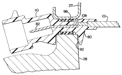
The embodiment of Figure 11 may be considered to be
identical to that of Figures 9 and 10 except that in this
embodiment the electrical Leads 101 within the valve cover
axe permanently connected to the conductors 82 as at 108 and
integrally molded therewith in the bridge 80 of the gasket
body while the exterior male multiple pin connector 110 has
a slightly different configuration and is angled slightly.
Although the various embodiments of the valve cover
gasket assembly with an electrical bridge are described in
connection with a diesel engine, it is to be understood that
the concepts disclosed herein are applicable to gasoline
engines as well, for example, to optimize electronic
injector placement under the engine valve cover. The gasket
assembly with an electrical bridge has a number of
advantages, some of which have been described and others of
which are inherent in the invention. Also, it is apparent
that modifications may be made to the invention without
departing from the teachings 'thereof. For example, the only
limitation on positioning of the electrical bridge 19 along
the gasket periphery is that it not come into contact with
the bolts for securing the valve cover to the cylinder head.
Accordingly, the invention is only to be limited as
necessitated by the accompanying claims.