Note: Descriptions are shown in the official language in which they were submitted.
134Q688
-18-
sensible. Dans ce sens, toute opération de compression longitudinale est
favorable puisque pour une même masse volumique finale, la vitesse du
convoyeur de réception peut être accrue.
Dans les deux cas considérés, les vitesses des convoyeurs
intermédiaires 9 et 10 d'une part et 11 et 12 d'autre part, s'établissent de
la
façon suivante: pour une opération de compression simple, la vitesse des
convoyeurs 9 et 10 est inchangée à 35 mlmin, celle des convoyeurs 11 et 12
et de l'étuve est comprise entre 7 et 10 m/min; pour une double compression
la vitesse de 9 et 10 est comprise entre 18 et 23 m/min et celle de 11 et 12
entre 7 et 10 m/min.
La hauteur à l'introduction du feutre entre les convoyeurs 7 et
8 est réglée légèrement supérieure à celle du feutre. La distance séparant
les convoyeurs 9 et 10 au point où ils sont proches l'un de l'autre est deux
fois l'épaisseur du produit final soit 100 mm. La même distance sépare les
convoyeurs 11 et 12.
Les mesures de résistance à la compression sont effectuées
selon la norme britannique BS 2972. Selon cette norme, un échantillon de
316 x 316 mm d'une épaisseur de 100 mm est soumis à une pression de
10%. La vitesse de déplacement des plateaux de compression est de 1
mm/min.
La figure 6 sur laquelle les résultats sont reportés sous forme
de graphique, montrent que pour une même résistance à la compression,
l'échantillon obtenu sans compression longitudinale lors de la formation du
feutre est celui qui requiert la masse volumique la plus importante. L'écart
avec l'échantillon du feutre ayant subi une compression longitudinale est de
l'ordre de 15%,ce qui est considérable.
II est encore plus remarquable de constater qu'un écart
d'environ 10% de masse volumique apparaît entre l'échantillon ayant subi
une seule compression et celui ayant subi deux compressions longitudinales.
Les tests effectués sur les mêmes produits pour déterminer la
résistance à l'arrachement sont de même nature. Les feutres ayant subi
x
2Q~25~~
1
SLACKLESS ROTARY DRAWBAR ASSEMBLY
BACKGROUND OF THE INVENTION
1. Field of the Invention: This invention
relates to a drawbar assembly for connecting together
5 railroad cars, in general, and, more particularly, to a
drawbar arrangement embodying a simplified construction
and arrangement of parts that includes a drawbar with a
truncated convex spherical end contained between a
front draft bearing surface formed integrally with a
10 drawbar support housing which is secured to a center
sill and a rear support block which is supported
against the housing by a gravity-activated wedge.
2. Description of the Prior Art:
As is known, most prior art railroad coupler
15 assemblies are relatively complicated and include a
draft sill, draft gear, yoke, follower block, striker,
pin or coupler connection and the coupler itself and
its associated components. Such conventional coupler
arrangements have a degree of free and cushioned slack.
20 That is, there is a certain amount of free "play"
between the coupler components when the load changes
from a draft to a buff load, and vice versa. At the
same time, the draft gear acts as a spring mechanism to
cushion impacts between adjacent cars. Research has
25 indicated that eliminating and free and cushioned slack
within a train can eliminate over the road train action
forces due to "run-ins" and "run-outs". The magnitudes
of these forces are large and cause significant wear
2
and tear on the rolling stock and in some instances are severe enough to cause
derailments.
Furthermore, in conventional coupler assemblies, the key or pin
connection of the coupler to the yoke is at a relatively long distance from
the
kingpin about which the wheel truck rotates. In negotiating curves,
particularly
under buff loading conditions, this gives rise to relatively large lateral
forces
which can cause derailments. The same is true when jackknifing occurs under
buff loads with lateral forces attempting to rotate the cars about their
centers.
An improvement to the aforesaid conventional coupler assemblies was
disclosed in United States Patent No. 4,580,686. While not limited thereto,
that
patent, as well as the present invention, was particularly adapted for use in
unit
train applications where cars are coupled and uncoupled for periodic
maintenance
and repair only. Such cars are not subjected daily to impact forces
associated
with bumping encountered in classification yards and, therefore, do not
require
cushioning devices such as draft gears.
Specifically, that patent provided a drawbar arrangement for coupling
railroad cars each having a center sill and trucks at its opposite ends, the
trucks
being pivotal about vertical kingpins. The arrangement
wa. 2022~~
3
included a drawbar having an enlarged spherical butt
end portion defining essentially convex spherical buff
and draft load surface, a rear support block having a
tapered rear surface and concave substantially
hemispherical buff load bearing surface adapted to
engage with the convex buff load bearing surface of the
butt portion, a slack adjusting wedge for engaging the
tapered surface of the rear support block, means for
transferring buff loads from the slack adjusting wedge
to the center sill, a front draft block having a
concave and substantially hemispherical draft load
surface adapted to engage with the convex draft load
surface of the enlarged spherical butt end portion, the
front draft block including an annular draft load
surface opposite the hemispherical draft load surface
thereof, a wear block having an annular draft load
surface adapted to engage the annular draft load
surface of the front draft block, and means supported
by the center sill for transferring a draft load from
the wear block to the center sill.
Preferably, the drawbar arrangement of U.S.
Patent No. 4,580,686 provided that the draft block and
the wear block each have an opening wherein the shank
of the drawbar extended in a direction which was
generally opposite the kingpin. The aforesaid means
supported by the center sill included a plurality of
draft stop lugs supported by the center sill. A sill
bottom plate was preferably secured to the center sill
2022J8~
4
for supporting one of the plurality of draft stop lugs.
The center sill included spaced-apart sill side walls
extending along opposite sides of a sill roof wall.
The drawbar arrangement preferably further included a
carrier plate supported by the center sill opposite the
roof wall thereof for supporting the rear support
block, front draft block and the wear block between the
side walls of the center sill. The tapered surface of
the slack adjusting wedge was preferably arranged to
extend in a vertical direction along the height of the
side walls of the outer sill. The tapered thickness of
the wedge was greater at the top thereof than at the
bottom for movement under the force of gravity between
the rear support block and the lugs supporting the
wedge on the center sill. An opening in the front
draft block was preferably longer in the vertical
direction than in the horizontal direction, whereby the
draft front block rotated with the drawbar shank
portion in a horizontal plane but not in a vertical
plane. Moreover, the rear support block and front
draft block rotated in an endless manner about an axis
extending substantially along a central longitudinal
axis of the shank relative to the convex spherical buff
and draft load surfaces. The pivotal action at the end
connections facilitated rotation, and permitted
360°rotation for negation of horizontal and vertical
track curves as well as rotary car dumping.
20~~~~
With an arrangement of that sort, free and
cushioned slack was eliminated form the interconnection
between cars, thus eliminating undesirable longitudinal
train action forces and reducing the risk of
5 derailment. The slackless connection between cars
provided thereby eliminated run-in and run-out of slack
between cars in reversals of draft and buff train
actions. That also eliminated the generation of large
forces due to relative accelerations between cars, thus
reducing wear and damage to car components, lading and
locomotives, thereby reducing maintenance cost. The
design of the drawbar reduced an estimated 650 pounds
from the tare weight of the car and eliminated
couplers, yokes, cushioning devices and strikers. At
the same time, the structure forming the pivotal
connection at each end of the drawbar could be
incorporated into existing center sills without
modification of the center sills. Moreover, the site
at which the structure used to interconnect the end of
the drawbar with the center sill could be located at
any desired location but preferably rearwardly of the
car to reduce lateral wheel force components. By
moving the pivot point of the drawbar toward the center
line of the bolster, car tracking through tight radius
curves was enhanced while reducing the potential for
track overturn plus wheel wear. That invention further
utilized a gravity-activated wedge which was arranged
to move vertically to compensate for wear and maintain
2022~~0
6
a slackless relationship of parts that interconnected
the drawbar with the car.
While the structure disclosed in U.S. Patent
No. 4,580,686 represented an improvement over prior
conventional coupler assemblies, it required rather
difficult assembly and disassembly and was subject to
significant wear caused by friction.
For example, if either the front load bearing
block or the wear block needed repair or replacement, a
l0 weld or other connecting means joining oppositely-
directed shanks which formed the drawbar had to first
be destroyed or otherwise removed to release the shanks
from one another. The drawbar could then be removed
from the center sill by removing the sill bottom cover
plate which held the front and rear load bearing blocks
about the enlarged spherical end portion of the
drawbar. Once the drawbar was removed from the sill,
the front block and/or the wear block were then
slidably removed from the shank. Then, a repaired or a
replacement front block and/or wear block was slid back
onto the shank of the drawbar. Upon completion of the
maintenance, the drawbar assembly was reassembled and
the oppositely-directed shanks were then rewelded or
otherwise connected to form a continuous drawbar.
Also, the large area of surface contact between
the spherical butt end portion of the drawbar and
mating spherical portions of the front draft block and
rear buff block led to the creation of significant
20~~~~~
friction between and, consequently, premature wearing
and failure of those contacting parts.
An advantage exists, therefore, for a slackless
rotary drawbar assembly which is easily assembled and
disassembled and which has a high degree of
reliability.
SUMMARY OF THE INVENTION
The present invention provides a slackless
rotary drawbar assembly for a railway car having a
center sill, the assembly comprising, a drawbar having
a shank portion extending to an enlarged truncated
spherical butt end portion defining essentially convex
spherical buff and draft load bearing surfaces, the
shank portion projecting from the convex spherical
draft load bearing surface, housing means secured to
the center sill for supporting the butt end portion
therein, the housing means having a top wall, a rear
wall and spaced side walls, the housing means further
having an essentially entirely open bottom portion,
concave surface means formed on the housing means and
bearing against the convex spherical draft load bearing
surface for transferring draft loads therefrom to the
center sill, a rear support block having a tapered rear
surface and a truncated concave substantially spherical
buff load bearing surface adapted to engage with the
convex buff load bearing surface of the butt end
portion, a gravity activated slack adjusting wedge for
engaging the tapered surface of the rear support block,
~~2~~
a detachable bottom support casting mounted to the center sill for retaining
the
butt end portion within the housing means, the bottom support casting having
concave surface means formed thereon which are alignable with the concave
surface means formed on the housing means in order to provide a continuous
concave surface which bears against the convex spherical draft load bearing
surface for transfernng draft loads from the convex spherical draft load
bearing
surface to the center sill; and means for detachably securing the bottom
support
casting to the center sill.
In another aspect of the invention, there is provided a slackless rotary
drawbar coupler assembly for use in combination with a railway car having a
center sill, the assembly comprising a drawbar having a shank portion
extending
to an enlarged truncated spherical butt end portion defining essentially
convex
spherical buff and draft load bearing surfaces, the shank portion projecting
from
the convex spherical draft load bearing surface, housing means securable to
such
center sill for supporting the butt end portion therein, the housing means
having a
top wall, a rear wall and spaced side walls, the housing means further having
an
essentially open bottom portion, concave surface means within the housing
means
adapted to bear against the convex spherical draft load bearing surface for
transferring draft loads therebetween, a rear support block having a tapered
rear
surface and a truncated concave substantially spherical buff load bearing
surface
adapted to engage with the convex buff load bearing surface of the butt end
portion, a gravity activated slack adjusting wedge for engaging the tapered
surface of the rear support block, a bottom support member detachably secured
to
the open bottom portion of the housing means for retaining the butt end
portion
.:_
8a
within the housing means, the bottom support member having a concave surface
means which is alignable with the concave surface means within the housing
means in order to provide a continuous concave surface adapted to bear against
the convex spherical load bearing surface for transferring loads therebetween.
In a further embodiment of the invention, there is provided a slackless
rotary drawbar coupler assembly for use in combination with a railway car
having a center sill, the assembly comprising a drawbar having a shank portion
extending to an enlarged truncated spherical butt end portion defining
essentially
convex spherical buff and draft load bearing surfaces, the shank portion
projecting from the convex spherical draft load bearing surface, the butt end
portion having upper and lower planar surfaces, housing means securable to
such
center sill for supporting the butt end portion therein, the housing means
having a
top wall, a rear wall and spaced side walls, the housing means further having
an
essentially open bottom portion; concave surface means within the housing
means adapted to bear against the convex spherical draft load bearing surface
for
transferring draft loads therebetween, a rear support block having a tapered
rear
surface and a truncated concave substantially spherical buff load bearing
surface
adapted to engage with the convex buff load bearing surface of the butt end
portion, a gravity activated slack adjusting wedge for engaging the tapered
surface of the rear support block, a bottom support member detachably secured
to
the open bottom portion of the housing means for retaining the butt end
portion
within the housing means, the bottom support member having a concave surface
means alignable with the concave surface means within the housing means
sufficient to provide a continuous concave surface adapted to bear against the
;t
sb ~0~~5 ~~
convex spherical draft load bearing surface on the drawbar for transferring
draft
loads therebetween, and a through-bore passing through the butt end portion
between the upper and lower planar surfaces adapted to permit air circulation
therethrough and reduce friction related heat within the assembly.
BRIEF DESCRIPTION OF THE DRAWINGS
Figure 1 is a schematic illustration of a prior art railroad coupler
arrangement showing the lateral forces which result under buff loads during
negotiation of a curve;
Figure 2 illustrates jackknifing motions and resultant forces exerted on
railroad cars during buff loads;
Figure 3 is a schematic illustration of a typical prior art slackless rotary
drawbar arrangement;
Figure 4 is an enlarged side view of the drawbar coupler arrangement of
Figure 3;
Figure 5 is a still further enlarged plan view of a prior art drawbar
coupling arrangement;
Figure 6 is an elevational view, in section, taken along line VI-VI of
Figure 5;
.r
9
Figure 7 is a front elevational view of the
prior art drawbar coupler arrangement shown in Figure
5;
Figure 8 is an elevational view, in section, of
the slackless rotary drawbar assembly of the present
invention as seen along the central longitudinal axis
thereof;
Figure 9 is an end view of the assembly as seen
along line IX-IX of Figure 8;
Figure 10 is an end view of the rotary drawbar
of the present invention as viewed axially along its
shank portion:
Figure 11 is a plan view, in partial section,
of the rotary drawbar support housing of the present
invention:
Figure 11A is an elevational view, in section,
of the rotary drawbar support housing of the present
invention;
Figure 12 a view of only the bottom support
casting of the present invention as seen in the
direction of the end view depicted in Figure 10;
Figure 12A is a plan view of the bottom support
casting as seen along line A-A of Figure 12;
Figure 12B is an elevational view of the bottom
support casting as seen along line B-B of Figure 12;
Figure 13 is a plan view of the slack
adjustment wedge of the present invention; and
10
Figure 13A is a view as seen along line A-A of
Figure 13.
DESCRIPTION OF THE PREFERRED EMBODIMENT
With reference now to the drawings, and
particularly to Figure 1, there is shown adjacent
railway cars 10 and 12, the car 12 being on a curved
track section 14. Each car 10 and 12 includes a center
sill 16 having a center plate 18 which reacts on the
bolster 20 of a wheel truck 22. Extending through the
center plate 18 is a kingpin, not shown, whose axis is
indicated generally by the reference numeral 24 and
about which the truck 22 can pivot in a horizontal
plane. Interconnecting the two cars 10 and 12 are
conventional couplers 26 and 28 which conventionally
include a draft gear, a yoke, a follower block, and a
pin or key coupler connection, the axis of the pin
being indicated by the reference numeral 30. Each
coupler can rotate in a horizontal plane about its
associated pin connection 30.
With the cars 10 and 12 under a buff load with
car 10 pushing the car 12, forces are imparted to the
couplers 26 and 28. As can be seen in Figure 1, the
longitudinal force F~ on the couplers is broken into a
lateral force FZ and a force F3 which extends along the
axis of the car. The lateral force F2 exerts a
sideways force on the truck 22 which is taken by the
wheel flanges. The force F2 also produces a moment
about the kingpin 18 tending to twist the car about its
20~2~80
11
center point. This lateral force produces relatively
severe stresses in the car and in some cases can cause
a derailment.
In Figure 2, a condition is illustrated wherein
three cars 32, 34 and 36 are undergoing jackknifing
motions under a buff load. Again, lateral forces FZ
are exerted on the cars at the connection of couplers
26 and 28 thereto, these forces tending to twist the
cars about their center points or centers of gravity.
The drawbar arrangement of the aforementioned
United States Patent Number 4,580,686 is shown in
Figures 3 and 4 wherein the couplers 26 and 28 of
Figure 1 are replaced by a drawbar 40 which is
pivotally connected at the ends of center sills 16.
The center sills 16 are preferably reduced in length so
that the ends of the drawbar 40 pivot about axes which
are as close as possible to the center 24 of trucks for
the car. As a result, the distance between the
longitudinal axis of the drawbar and the central axis
of each car 10 and 12 is much less, resulting in a
lower wheel flange to rail force produced by force F2.
In addition, there is a reduced moment about the
kingpin whose axes are indicated by the reference
numeral 24.
With reference now to Figures 5-7, a specific
embodiment of the drawbar assembly according to United
States Patent Number 4,580,686 is shown. The end
portion of the center sill 16 is illustrated and takes
~0~~~8~
12
the form of a conventional "z" sill. Rear draft lugs
42 are secured as by welding to spaced-apart side walls
16A of the Z-sill. A flange 16B projects laterally
from the lower edge of each side wall 16A. A slack
adjusting wedge 44 is seated against the rear draft
lugs for support thereby. The wedge has a vertically-
tapered surface 45 in contact with a mating tapered
surface on a rear support block 46. The wedge is
arranged so that the force of gravity acting on the
wedge exerts a continuous force against the rear
support block 46. The tapered surface on the rear
support block is at the rear thereof and opposite this
surface is a concave, substantially hemispherical buff
load bearing surface 47 adapted to engage with a convex
buff load bearing surface 48 forming part of a
spherical butt end portion 49 at the end of drawbar 40.
A shank 50 projects from a convex spherical draft load
bearing surface 51 that is seated against a
hemispherical draft load surface formed in a front
draft block 52. An annular draft load surface 53 faces
a forward direction which is opposite the rearwardly-
directed hemispherical draft load surface of the front
draft block. As shown in Figure 5, the annular draft
load surface is curved between the side walls 16A of
the center sill and engages with a mating annular draft
load surface defined on a wear block 54. The front
draft block 52 and wear block 54 are each provided with
an opening through which shank 50 extends.
~~~~~8~
.~.~
13
The draft load which is transferred to the wear
block is distributed to the center sill by means which
in the embodiment shown in Figures 5-7, comprises a
plurality of lugs 55. There are four lugs illustrated,
one of which is welded to a top wall of the center sill
to project downwardly into the space between the side
walls 16A thereof and engages the forwardly-directed
face of wear block 54. A second and third of the lugs
55 are welded to side walls 16A so that the lugs engage
with the forwardly-directed face of the wear.block. A
fourth of the lugs is welded to a bottom cover plate
56, the latter being secured preferably by nut and bolt
assemblies 57 to each of the flanks 16B. Thus, it can
be seen that the lugs 55 extend from the side walls of
the center sill and the bottom plate 56 into the space
enclosed by the sill and the bottom plate. The faces
of the lugs which are opposite each other are tapered
so that the shank 50 of the drawbar can move back and
forth in both the horizontal and vertical directions.
The lugs efficiently transfer the pull forces from the
drawbar by way of the front draft block 52 and wear
block 54 to the center sill. Clearances between the
rear support block 46 and the enlarged spherical butt
end portion 49 are eliminated by the slack adjusting
wedge 44 due to the continued force of gravity urging
the wedge downwardly and thereby eliminating any
clearances between the parts.
w~ 2022~~0
14
To transmit buff loads, the forces imposed on
shank 50 are transferred by the rear support block 46
through the slack adjusting wedge 44 to the rear draft
lugs 42 and thereby to the center sill. The tapering
surface of the wedge is selected so that the wedge will
not retreat vertically under the imposed forces,
thereby consistently maintaining a metal-to-metal
contact relationship between all of the parts situated
between the rear draft lugs 42 and front draft lugs 55.
Should it be necessary for the purpose of disassembling
the drawbar to relieve the clamping force provided by
the slack adjusting wedge 44, an instrument such as a
pushbar (not shown) can be inserted at the rear edge of
plate 56 into contact with lower edge of the wedge to
displace it vertically.
The drawbar 40 in the embodiment of Figure 3
and 4 is formed in two shank halves 50 interconnected
by a weld joint 60 which comprises a suitable layer of
weld metal applied to a groove formed by chamfered
surfaces 61 on the projected ends of the shank halves.
A shaft member 62 extends between at the end faces of
the shank halves to maintain a coaxial aligned relation
during the welding process. Other means for
interconnecting the shank halves can be used, if
desired.
As one can readily appreciate, if either the
front load bearing block 52 or the wear block 54 needed
repair or replacement, the weld 60 (or other connecting
2~~Z~~
means) which joined the oppositely-directed shanks 50
had to first be destroyed or otherwise removed to
release the shanks 50 from one another. The drawbar 40
could then be removed form the center sill 16 by
5 removing the sill bottom cover plate 56 which holds the
front and rear load bearing blocks 52 and 46 about the
enlarged spherical end portion 49 of the drawbar. Once
the drawbar was removed from the sill, the front block
52 and/or the wear block 54 could then be slidably
10 removed from the shank 50. Afterward, a repaired or
replacement front block 52 and/or wear block 54 could
be slid back onto the shank 50 of the drawbar. Upon
completion of the maintenance, the drawbar assembly was
reassembled and the oppositely-directed shanks 50 were
15 then rewelded or otherwise connected to form a
continuous drawbar.
As will be seen, the construction of the
drawbar assembly of the present invention affords much
simpler and less time-consuming maintenance to be
performed on the drawbar assembly.
Also, when one considers Figure 5 and 6, it can
be seen that virtually the entire surface area of the
enlarged convex spherical portion 49 of the drawbar 40
is in contact with mating concave spherical surfaces
formed on both the front and rear load bearing blocks
52 and 46. Such a large area of surface contact leads
to the creation of significant friction between and,
2022~8~
16
hence, premature wearing and failure of those
contacting parts.
As will be described below, the construction
according to the present invention greatly reduces the
contact area between the spherical portion of the
drawbar and the surfaces which contact and support the
spherical portion to thereby greatly reduce the
friction therebetween and the likelihood of premature
wear and failure of those contacting parts.
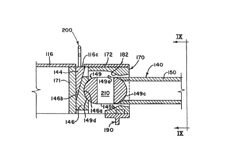
Referring now to Figure 8, there is depicted
the slackless rotary drawbar assembly 140 constructed
in accordance with the present invention. The assembly
140 includes a rotary drawbar support housing 170 which
is welded or otherwise suitably secured into center
sill 116. Support housing 170 includes a rear wall
171, top wall 172 and side walls 173 and 174. As most
clearly seen in Figures 11 and 11A, top wall 172 has an
aperture 172A formed therein, the function of which is
described in greater detail hereinbelow.
Along their lower portions and toward a forward
region of the support housing 170 each of the side
walls 173 and 174 has formed thereon a laterally
inwardly protruding formation. One of these
formations, as can be best seen in Figures 11 and 11A,
is formed on side wall 174 and is represented by
numeral 174A. An identical formation 173A is provided
on side wall 173 in direct opposition to formation 174A
and can be seen in Figure 9.
~o~~~~o
17
A space 180 is formed at the forward end of the
support housing 170 between sidewalls 173 and 174. It
is through space 180 that the shank 150 of the drawbar
passes for connection with a similar but oppositely-
directed drawbar shank 150 in a manner similar to that
depicted in Figure 4. A concave spherical surface 182
is formed on formation 173A, side wall 173, top wall
172, side wall 174 and formation 174A. As will be
described in more detail hereinbelow, a complementary
concave spherical surface 182A is provided on a bottom
support casting 190 (Figures 12, 12A and 12B). When
properly assembled, concave spherical surfaces 182 and
182A form a continuous concave draft loading surface.
Bottom support casting 190 is preferably fastened by
nut and bolt assemblies 157 to flanges 116B which
project laterally outwardly from sidewalls 116A of the
"z" sill 116 as illustrated in Figure 9.
At such time when the bottom support casting
190 is not attached to the support housing 170,
virtually the entire bottom of the housing 170 is open
to receive an enlarged truncated convex spherical butt
end portion 149 of the drawbar. When it is desired to
secure the drawbar within the support housing 170, the
truncated spherical portion 149 is positioned within
the support housing and bottom support plate 190 is
fastened by nut and bolt assemblies 157 to flanges 116B
of sill 116. Except where it contacts the continuous
surface formed by concave surfaces 182 and 182A and
2~22~~~
18
also where it contacts a rear support block 146, the
butt end portion 149 is sized so as to form clearances
between its outer surface and the inner surfaces of the
top wall 172 and side walls 173, 174 of housing 170.
As is most clearly seen in Figures 8 and 10,
truncated spherical portion 149 is substantially oblate
spheroidal in shape with truncated upper and lower
portions formed by planar upper and lower surfaces 149A
and 149B. A forward, substantially hemispherical,
draft load bearing surface 149C of truncated convex
spherical portion 149 is matingly received in the
continuous ring-like concave draft load bearing surface
formed by concave surfaces 182 and 182A. A similar
rearward, substantially hemispherical, buff load
bearing surface 149D of truncated convex spherical
portion 149 is matingly received in a truncated concave
spherical surface 146A formed in the rear support block
146.
Assembly of the drawbar assembly 140 is as
follows. Oppositely-directed ends of shank halves 150
are first joined by welding or other suitable means to
form a continuous drawbar in a manner similar to that
illustrated in Figure 4. Then, as noted previously,
the truncated spherical portion 149 is positioned
within the support housing 170 through the open bottom
thereof and bottom support plate 190 is then fastened
to flanges 116B of sill 116 by nut and bolt assemblies
2~~~~~~
19
157 in order to retain the truncated spherical portion
149 within the housing.
Rear support block 146 is then inserted
simultaneously with slack adjustment wedge 144 upwardly
through the open bottom of support housing 170
rearwardly of the buff load bearing surface 149D of the
truncated spherical portion 149. During this step, the
slack adjustment wedge 144 is held sufficiently
upwardly relative to the rear support block 146 to
permit unrestricted passage of the rear support block
upwardly through the bottom of the housing until such
time that its concave spherical surface 146B matingly
receives convex spherical surface 149D. The wedge 144
is held upwardly by an operator who grasps a lifting
ring 200 which is secured to the wedge and which passes
through aperture 172A in top wall 172 of housing 170 as
well as an aperture 116C formed in the top wall of the
sill 116.
When the concave spherical surface 146B is in
full contact with convex spherical surface 149D the
wedge 144 is then lowered by the operator. The rear
surface of the wedge 144 slides vertically relative to
the forward surface of the rear wall 171 of support
housing 170. The downward sliding of the wedge 144
under its own weight, and by additional means to be
described herebelow, causes the tapered forward surface
thereof to cooperate with the rearward tapered surface
of the rear support block 146 in order to remove any
202280
slack which exists between the various parts of the
drawbar assembly. The system thus operates in a manner
analogous to that described above with regard to the
prior art wedge and rear support block system
5 illustrated in Figures 5 and 6. As with the prior art
device, the tapering surface of the wedge 144 is
selected to be at an angle such that the wedge will not
retreat vertically under the imposed forces, thereby
consistently maintaining a metal-to-metal contact
10 relationship between all of the parts situated between
and including the rear wall 171 and the concave
surfaces 182 and 182A of the housing 170 and bottom
support casting 190, respectively.
Referring again to Figures 8 and 9 and also the
15 Figures 11, 11A, 12, 12A and 12B, it can be seen that
the outer portion of the space 180 formed by support
housing 170 and bottom support casting 190, through
which shank 150 extends, forms a continuous flared or
tapered surface. The portion of the continuous tapered
20 surface on support housing 170 is designated as numeral
183 and the portion on bottom support casting 190 is
designated as numeral 183A. The tapered surface
increases the range of motion of the shank portion 150
of the drawbar as it moves universally across space
180. The angle of taper "a " ranges between about 7°
and 13° with the greatest angle of taper being along
the side portions of the continuous tapered surface to
21
permit maximum lateral pivoting of the drawbar along
particularly sharp bends in the rail track.
Advantageous features of the bottom support
casting 190 and its connection to the support housing
170 are illustrated in Figures 8, 9, 12, 12A, and 12B.
Casting 190 includes a base 191 having apertures 192
formed in opposite ends thereof. Fasteners such as nut
and bolt assemblies 157 extend through apertures 192
and attach casting 190 to flanges 116B of sill 116. A
rib 193 extends along the bottom surface of the base
191 to increase the rigidity and strength of the
casting 190. Projecting upwardly from the upper surface
of the base 191 are a pair of spaced lug means 194
which extend into and closely interlock with spaced
mating pockets 195 formed in the bottom surfaces of the
laterally inwardly protruding portions 173A and 174A of
sidewalls 173 and 174, respectively. The interlock
between lug means 194 and pockets 195 provides a
locking lateral, vertical and axial interconnection
between the casting 190 and the housing 170 to ensure
the formation of a smooth, continuous concave spherical
surface 182 and 182A for mating with the convex
spherical surface 149C.
In Figures 13 and 13A there are illustrated
details of the slack adjustment wedge 144. As noted
previously, the wedge has secured thereto and upwardly
extending therefrom a lifting ring in the form of
eyebolt 200. Lifting ring 200 further serves as a wear
2o~2W~
22
indicator means. The wedge 144 may further be
provided, if desired, with bores 202 for receiving
biasing means such as springs (not shown). The springs
would bear against the undersurface of the sill 116 on
either lateral side of the aperture 116C to bias the
wedge 144 downwardly to further ensure that the wedge
does not become vertically displaced and, hence,
surface 149D from becoming dislodged from surface 146A
under buff loading, draft loading and/or axial rotation
forces exerted by the drawbar.
When maximum wear has occurred in the assembly
140 to where the wedge has "bottomed out", the wedge
will have no more effect in eliminating additional
slack. When this condition occurs, a colored wear
indicator on the vertical portion of the eyebolt will
no longer be visible above the sill. This will
indicate that the system has to be adjusted, either by
shimming, welding, or using an oversized wedge to take
up any additional slack. When the system has to be
adjusted, the wedge can be lifted up with the eyebolt
to break the force between the parts. At such time,
the rear support block 146 may be removed, followed by
bottom support casting 190, and then the various parts
of the assembly 140 can be easily modified or replaced
as necessary.
An important advantage provided by the
construction of the slackless rotary drawbar assembly
140 of the present invention is that eliminates the use
23
of a separate draft bearing block assembly like blocks
52 and 54 depicted in Figures 5 and 6. As such, the
present invention advantageously reduces the number of
parts thus simplifying and enhancing the accuracy of
the assembly and disassembly of the device.
Still further, the present invention completely
eliminates the need for disconnecting the
interconnected shank halves 150 in order to perform
maintenance on the drawbar assembly. On the other
hand, the shank halves 50 of the prior art drawbar
assembly 40 had to first be disconnected from one
another if repair or replacement of either the front
draft load bearing block 52 and/or the wear block 54
was required. As one can readily appreciate, the
present construction not only simplifies maintenance of
the assembly but also reduces the time, labor and costs
associated therewith.
Another advantage provided by the present
construction is that it inherently requires less
maintenance than the prior art device disclosed in
Figures 5 and 6. As noted at the outset, and as can be
clearly seen in a comparison of the drawbar assembly of
the present invention as illustrated in Figure 8 with
that of the prior art as seen in Figure 6, only a very
small surface area of the truncated spherical portion
149 of the drawbar is in contact with the rear support
block 146 and the housing 170; while in the prior art
device virtually the entire outer surface area of the
2~22~~~
24
spherical end 49 of the drawbar is surrounded by and in
contact with mating spherical surfaces on the draft and
buff load bearing blocks 52 and 46.
Such a large area of surface contact between
spherical buff end portion 49 and the mating spherical
surfaces of the front draft block 52 and rear buff
block 46 leads to the creation of significant friction
between and, consequently, premature wearing and
failure of those contacting parts.
By greatly reducing the area of contact between
the truncated spherical portion 149 and the housing 170
and rear support block 146, the present construction
thus eliminates a significant amount of damaging
friction. Accordingly, the present construction
reduces the frequency of maintenance associated with
the repair or replacement of parts which are subject to
premature wear or other friction-related heat damage.
Further enhancing this effect is the provision
of a through-bore 210 (Figure 8) extending between
planar surfaces 149A and 149B of truncated spherical
portion 149. With such a provision, air entering from
the open bottom of the housing 170 is permitted to pass
into the space above the upper planar surface 149A not
only through the spaces formed between the outer
surface of the truncated spherical portion 149 and the
side walls 173, 174, but also through the through-bore
210.
25
Through-bore 210, in combination with the
spaces formed between the outer surface of portion 149
and the side walls 173, 174 permits air to at all times
cool sizable portions of both the interior and exterior
of the truncated spherical portion 149 to further
resist friction-related heat damage to portion 149 as
well as the parts in contact therewith.
While the present invention has been described
in connection with the preferred embodiments of the
various figures, it is to be understood that other
similar embodiments may be used or modifications and
additions may be made to the described embodiment for
performing the same function of the present invention
without deviating therefrom. Therefore, the present
invention should not be limited to any single
embodiment, but rather construed in breadth and scope
in accordance with the recitation of the appended
claims.