Note: Descriptions are shown in the official language in which they were submitted.
2022~8
5DRAINAGE VATVE HAVING A FLEXIBLE
FLAP WITH AN EDGE TAPER
10BACKGROUND OF THE INVENTION
1. Field of the invention:
The present invention relates to a
drainage valve for installation into a water draining
conduit. In accordance with the invention, this valve
comprises a flexible flap formed with an edge taper to
improve water imperviousness.
2. Brief description of the prior art:
United States patent No. 4,621,945 granted
to Schafer et al. on November 11, 1986, illustrates
and describes a drainage valve of the above type for
installation into an underground water draining
conduit. The valve of Schafer et al. comprises a
perforated plate on the upstream surface of which is
applied a flexible flap. The upper portion of the
flap is attached to the upper portion of the
perforated plate through screw and nut assemblies.
The lower portion of the flap can be lifted by means
of a cord extending into a riser pipe and fixed to the
lower flap portion through a bracket. A block element
attachable to a pole member is also secured to the
upper portions of the flap and plate through the above
mentioned screw and nut assemblies to enable
installation of the valve into the underground
202292~
draining conduit from the surface of the ground
through the riser pipe.
The drainage valve of Schafer et al.
presents the following drawbacks:
- the flap is of even thickness over its
entire surface; this results in a lack of
imperviousness between the plate and flap as the
pressure applied on the flap by water upstream of the
valve is not sufficient to produce a tight joint by
forcing the periphery of the flap on the upstream
surface of the perforated plate:
- the O-ring placed between the plate and
an inner flange of the underground water draining
conduit can cause leakage of water through the valve;
- the bracket fixed to the lower portion
of the flap requires special cutting out of the plate
which often causes water leakage through the valve;
and
- the block element is in the form of a
parallelepiped and comprises exposed acute edges which
can cause obstruction upon lifting of the lower
portion of the flap through the cord attached to the
bracket.
OBJECT OF THE INVENTION
An object of the invention is therefore
to provide a drainage valve for installation into a
~02~928
water draining conduit which eliminates the above
mentioned drawbacks of the prior art.
SUMMARY OF THE INVENTION
More specifically, in accordance with the
present invention, there is provided a drainage valve
for installation into a water draining conduit,
comprising (a) a plate provided with apertures therein
to enable water to flow through this plate defining an
upstream surface, (b) means for mounting the plate
within the water draining conduit with the plate
extending across the conduit, these plate mounting
means including means for sealing a peripheral joint
between the plate and an inner surface of the conduit,
(c) a flap made of flexible material and applied
against the upstream surface of the plate, which flap
comprising an upper portion, a lower portion, and a
peripheral edge taper emcompassing the apertures of
the plate whereby pressure applied on the flap by
water upstream of the drainage valve forces the edge
taper against the upstream surface of the plate to
form a peripheral, sealed joint between these flap and
plate, (d) means for attaching the upper portion of
the flap to a corresponding upper portion of the
plate, and (e) means for lifting the lower portion of
the flap to drain water upstream of the drainage valve
through the apertures of the plate.
As the edge of the flap is tapered, it has
an increased flexibility and accordingly less water
pressure is required to force it against the upstream
~2292~
surface of the flap and produce a peripheral, tight
joint.
In accordance with a preferred embodiment
of the invention, the flap comprises an integral
elongated bracket member having a first end connected
to the lower portion of the flap on the upstream
surface of this flap and a second free end with a hole
therein. As this bracket member is integral with the
flap, it requires no cutting out of the plate which
can eventually cause water leakage through the
drainage valve.
Advantageously, the above mentioned joint
sealing means comprises the plate formed with a
peripheral groove rectangular in cross section and a
hollow tube inserted into that groove and made of
flexible material such as pure gum rubber or other
synthetic or natural material having similar
properties, and the plate mounting means comprises
spring clips peripherally distributed on a downstream
surface of the plate and capable of clamping an
annular, inner flange of the water draining conduit to
press the hollow tube between the groove and the inner
flange. When pressed by the clips between the groove
and the inner flange, the hollow tube eliminates any
water leakage through the joint between the plate and
conduit.
According to another preferred embodiment
of the present invention, the drainage valve comprises
a block element removably attachable to a pole member
and fixed on an upstream surface of the upper portion
2 3 ~
of the flap to enable installation of the drainage
valve through a riser pipe section connected to the
water draining conduit. This block element has the
form of a parallelepiped and comprises rounded edges
to prevent the said block element to cause obstruction
upon lifting of the lower portion of the flap through
a cord attached to the lower flap portion and
extending in the riser pipe section.
The means for attaching the upper portion
of the flap to the upper portion of the plate may
comprise screw and nut assemblies traversing both the
flap and the plate, and washer elements made of rigid
material and disposed in respective holes of the flap.
Each washer element is traversed by a respective screw
of said assemblies to prevent crushing of the flexible
material of the flap upon tighening of the screw and
nut assemblies.
The objects, advantages and other features
of the present invention will become more apparent
upon reading of the following non restrictive
description of a preferred embodiment thereof, given
by way of example only with reference to the
accompanying drawings.
BRIEF DESCRIPTION OF THE DRAWINGS
In the appended drawings:
Figure 1 is a cide elevation view,
partially cross sectional, of an embodiment of the
drainage valve in accordance with the present
~2~2~
invention for installation into a water draining
conduit;
Figure 2 is a rear view of the drainage
valve of Figure 1 showing in particular the
disposition of the spring clips;
Figure 3 is a cross sectional view, taken
along axis A - A of Figure 2, of the drainage valve of
Figures 1 and 2 installed in a water draining conduit;
Figure 4, which is disposed on the same
sheet of formal drawings as Figure 1, is an enlarged,
cross sectional view of the lower portion of the
drainage valve of Figure 3, showing movement of this
valve upon installation thereof; and
Figure 5 is an enlarged, cross sectional
view of the upper portion of the drainage valve of
Figures 1, 2 and 3, taken along axis B-B of Figure 2.
DETAILE~ DESCRIPTION OF THE PREFERRED EMBODIMENT
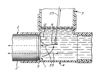
Referring now to the appended drawings,
the drainage valve in accordance with the present
invention is generally identified by the reference
numeral 1 and is installed into an underground and
cylindrical water draining conduit 2 through a riser
pipe 3 having a lower end connected to the conduit 2
through a T-shaped junction 4 and an upper end
emerging from the ground. Interposed between the
junction 4 and the proximate end of the conduit
section 2' is a ring defining in the conduit 2 an
7 2022~28
annular flange 6 (Figure 4). The inner surface of the
conduit 2 therefore presents an annular flange 6
positioned close to the riser pipe 3.
As illustrated, the drainage valve
comprises a plate S with apertures such as 7 therein,
a flap 8 applied on the upstream surface of the plate
s, three spring clips 9, 10 and 11 mounted on the
downstream surface of the plate S, and a block element
12 removably attachable to a pole member 13 (Figure 3)
in order to install the valve 1 in the conduit 2 from
the surface of the ground through the riser pipe.
The flap 8 is made of pure gum rubber or
lS of any other synthetic or natural material having
- similar properties. It is accordingly very flexible.
The flap 8 presents a peripheral edge taper 14 making
the periphery of this flap more flexible. One can
appreciate that less pressure applied on the flap 8 by
water upstream of the valve 1 is required to force the
edge taper 14 against the upstream surface of the
plate 5 to produce a peripheral, tight joint between
these flap and plate. The flexibility of the edge
taper 14 is important to seal the joint between the
flap 8 and the plate 5 in particular when the level of
water in the conduit 2 upstream the valve 1 is lower
than the the height of this valve.
As can be seen in particular in Figure 3,
the diameter of the flap 8 is substantially the same
as the diameter of the plate S whereby the apertures
7 are encompassed by the edge taper 14.
2~Z~928
The upper portion of the flap 8 is secured
to the upper portion of the plate 5 through a pair of
screw and nut assemblies 15 and 16 made of stainless
steel. More specifically, the flap 8 is pressed by
the assemblies 15 and 16 between the plate 5 and the
block element 12. The heads of the screws 15' and 16'
abut against shoulders such as 17 (Figure 5) formed in
holes such as 18 of the element 12. The heads of
these two screws therefore penetrate the material of
the block element 12 to cause no obstruction upon
lifting of the lower portion of the flap 8 as will
become apparent from the following description. The
screws 15' and 16' then pass through respective washer
elements such as 19 (Figure 5) made of rigid plastic
material and inserted into holes such as 20 in the
upper portion of the flap 8, and through respective
holes such as 21 in the plate 5. Lock nuts 15~ and
16~ (Figure 2) are then screwed on the threaded ends
of the screws 15' and 16' emerging from the downstream
surface of the plate 5.
o-rings such as 22 made for example of
rubber material are respectively crushed between the
heads of the screws 15- and 16' and the shoulders such
as 17 to ensure imperviousness of the joint between
these screw heads and the block element 12.
The rigid washer elements such as 19 are
somewhat thinner than the flap 8; the latter flap is
approximately 0.010 - 0.020 inch thicker than the
washer elements 19. The function of the elements 19
is to prevent crushing of the flap 8 when the screw
and nut assemblies 15 and 16 are tightened by screwing
9 2022928
the nuts 15~ and 16~, which crushing can cause tilting
of the flap 8 and lack of imperviousness to water of
the valve 1. The flap 8 i8 however sufficiently
pressed to ensure imperviousness between the flap 8
and the block element 12 and between the flap 8 and
the plate 5.
An elongated bracket member 23 (Figures
3 and 4) is integrally formed onto the upstream
surface of the lower portion of the flap 8. This
elongated member 23 is therefore made of the same
flexible material as the flap 8 and has a first end
connected to the latter flap and a second free end
provided with a hole 24 to attach a cord 25 permitting
to lift the lower portion of the flap 8 when water
upstream of the valve 1 is to be drained. This
integrally formed bracket member 23 requires no
special cutting out in the plate 5 which can cause
leakage of water through the valve 1.
The plate 5 is made of PVC (polyvinyl
chloride), grade 1, type 1. It comprises apertures 7
encompassed by the edge taper 14 of the flap 8 and
positioned to enable mounting of the three spring
clips 9, 10 and 11 thereon. It should be pointed out
here that the edge taper 14 enables provision of a
greater number of apertures 7 through the plate 5 as
it produces a tighter joint between the flap 8 and the
periphery of the downstream surface of the plate 5.
The downstream surface of the plate is
also formed with a peripheral groove 26 generally
rectangular in cross section. Inserted into this
2 ~ 8
groove 26 is a sealing hollow tube 27 made of pure gum
rubber or of any other synthetic or natural material
having similar properties.
The three spring clips 9, 10 and 11 are
120 degrees apart and are distributed over the
periphery of the downstream surface of the plate 5.
These clips are V-shaped and are made of spring
stainless steel. They are fixed to the plate through
screws 28, 29 and 30, respectively, and comprise outer
arms 9', 10' and 11' with a zigzag free end to clamp
the inner flange 6 of the conduit 2. When they clamp
the flange 6, the clips 9, 10 and 11 press the hollow
tube 27 between the groove 26 and this flange 6. Due
to the distribution of the clips 9, 10 and 11, a
substantially uniform pressure is applied over the
length of the tube 27. As can be appreciated by one
skilled in the art, the rectangular groove 26 and the
hollow tube 27 can produce a very tight joint with a
relatively low pressure applied on the tube 27.
The block element 12 has the form of a
parallelepiped and its exposed edges such as 31 and 32
(Figure 3) are rounded to cause no obtruction upon
lifting of the lower portion of the flap 8 to drain
water through the apertures 7 of the plate 5 as shown
by the arrows 33 (Figure 1). Indeed, the cord 25 and
bracket member 23 can slide on these rounded edges 31
and 32. The upper end of the cord 25 can for example
be attached to a float (not shown) disposed into the
riser pipe 3 and responsive to the level of the
underground water table to lift the lower portion of
the flap 8.
11 2022928
The block element 12 also comprises a
threaded vertical hole 34 in which the pole member 13
with a threaded end 13' can be screwed to enable
installation of the valve 1 from the surface of the
ground through the riser pipe 3. To install the valve
1, it should be moved in the direction 35 (Figure 4)
until the clips 9, 10 and 11 clamp the flange 6. The
pole member 13 is then unscrewed and removed and the
valve 1 operated through the cord 25. When the valve
1 should be removed for example for maintenance
purposes, the pole member 13 is screwed in the hole 34
and using this pole member 13, the clips 9, 10 and 11
are disengaged from the inner flange 6 and the valve
1 removed through the riser pipe 3.
Although the present invention has been
described hereinabove by way of a preferred embodiment
thereof, such an embodiment can be modified at will,
within the scope of the appended claims, without
departing from the spirit and nature of the subject
invention.