Language selection

Search

Patent 2023042 Summary

Third-party information liability

Some of the information on this Web page has been provided by external sources. The Government of Canada is not responsible for the accuracy, reliability or currency of the information supplied by external sources. Users wishing to rely upon this information should consult directly with the source of the information. Content provided by external sources is not subject to official languages, privacy and accessibility requirements.

Claims and Abstract availability

Any discrepancies in the text and image of the Claims and Abstract are due to differing posting times. Text of the Claims and Abstract are posted:

  • At the time the application is open to public inspection;
  • At the time of issue of the patent (grant).
(12) Patent: (11) CA 2023042
(54) English Title: SEALED DOWNHOLE MOTOR DRIVE SHAFT UNIVERSAL JOINT ASSEMBLY
(54) French Title: JOINT A CARDAN POUR ARBRE D'ENTRAINEMENT DE MOTEUR ETANCHE A FOND DE FORAGE
Status: Term Expired - Post Grant Beyond Limit
Bibliographic Data
(51) International Patent Classification (IPC):
  • E21B 4/00 (2006.01)
(72) Inventors :
  • WENZEL, DOUGLAS (Canada)
  • WENZEL, ROBERT (Canada)
  • WENZEL, WILLIAM (Canada)
(73) Owners :
  • DOUGLAS WENZEL
  • ROBERT WENZEL
  • WILLIAM WENZEL
(71) Applicants :
(74) Agent: DOUGLAS B. THOMPSONTHOMPSON, DOUGLAS B.
(74) Associate agent:
(45) Issued: 1994-04-12
(22) Filed Date: 1990-08-09
(41) Open to Public Inspection: 1991-03-13
Examination requested: 1991-03-15
Availability of licence: N/A
Dedicated to the Public: N/A
(25) Language of filing: English

Patent Cooperation Treaty (PCT): No

(30) Application Priority Data: None

Abstracts

English Abstract


ABSTRACT OF THE DISCLOSURE
A Sealed Downhole Motor Drive Shaft Universal Joint
Assembly consisting of a housing with an interior and an
exterior surface. The interior has an end wall and side
walls. The end wall has an elongate projection with a
concave terminus. The side walls have a plurality of slots.
A shaft is provided having an exterior surface and opposed
ends. Each of the ends has a central cavity with a
substantially concave end wall. The exterior surface of the
drive shaft has a plurality of annularly spaced pockets
adjacent each end. The pockets are in substantial alignment
with the end wall of the central cavity. Each end of the
drive shaft is telescopically received within one of the
housings. A thrust ball is positioned between the concave
terminus of the elongate projection of the housing and the
concave end wall of the central cavity of the shaft thereby
transmitting thrust loads between the housing and the shaft
while permitting omni-directional relative movement of the
housing and the shaft. A plurality of ball bearings are
positioned in the pockets of the shaft and the slots of the
housing thereby transmitting radial loads between the housing
and the shaft while permitting omni-directional relative
movement of the housing and the shaft. An end cap engages
the external surface of the housing thereby preventing the
separation of the shaft and the housing. Seals are disposed
between the end cap and the housing to prevent the entry of
drilling fluids into the housing.


Claims

Note: Claims are shown in the official language in which they were submitted.

THE EMBODIMENTS OF THE INVENTION IN WHICH AN EXCLUSIVE PROPERTY
OR PRIVILEGE IS CLAIMED ARE DEFINED AS FOLLOWS:
1. A Sealed Downhole Motor Drive Shaft Universal Joint Assembly,
comprising:
a. a housing with an interior and an exterior surface, the
interior having an end wall and side walls, the end wall having
an elongate projection with a concave terminus, the side walls
having a plurality of slots;
b. a shaft with an exterior surface and opposed ends, each
of the ends having a central cavity with a substantially concave
end wall, the exterior surface of the drive shaft having a
plurality of radially spaced pockets adjacent each end in
substantial alignment with the end wall of the central cavity,
the drive shaft being telescopically received within the housing
with the central cavity in axial alignment with the elongate
projection in the housing;
c. a thrust ball positioned between the concave terminus
of the elongate projection of the housing and the concave end
wall of the central cavity of the shaft thereby transmitting
thrust loads between the housing and the shaft while permitting
limited omni-directional relative movement of the housing and the
shaft;
d. a plurality of ball bearings positioned in the radially
spaced pockets of the shaft and the slots of the housing thereby
transmitting radial loads between the housing and the shaft while
permitting limited omni-directional relative movement of the
housing and the shaft;
e. an annular end cap engages the exterior surface of the
housing, the end cap engaging the end of the shaft upon an axial
force being exerted thereby preventing the axial separation of
the shaft and the housing;
f. seals disposed between the end cap and the housing to
prevent the entry of drilling fluids into the housing; and
g. a passage extending from the housing exterior surface
through the housing to the housing end wall, for continuously
allowing, in use, drilling fluids to enter the passage thereby

creating an internal pressure within the lubricant filled
interior of the housing which is equal to pressure external of
the universal joint housing.

Description

Note: Descriptions are shown in the official language in which they were submitted.


~`~ 2~2~
: .
THe pres~rJI: inverlt;oiJ I~l~te~i to ~ Seale(3 Dov~rlllole
Motor Drive Shaft Universal Joint Assembly.
BAC~GROUND OF THE INVENTION
, 5 Tlle output shaft of a Dowrlhole motcr used wit~lin
-~ the oil industry for earth borirly operations moves in an
;~ eccell-tric fashiorl. This eccelltric movemerlt must be
converted into a concerltric movement for the drill bit
to perform its intended functiorl. At -the present time
10 thi~ conversion is accomplished by means of a drive
s~laf-t havirly universal joint connectiorls which connects
the downhole motor to a bearing assembly rotating the
drill bit,
The penetration of abrasive drilling fluids into
the drive shaft universal joint assembly has an adverse
effect on the operational life of the drive shafts. In
order to prolong this operational life, attempts have
been made to seal the universal joint assernblies. The
¦20 universal joirlt as9emblies of most drive shafts do not
,~readily lend t~lemselves to sealiny. It has therefore
come to be the practise to secure a lubricant filled
¦rubber sleeve over the universal joint. This sleeve has
a number of recogniYed disadvantages. It is common for
25 it to slide out of positiorl, where it can become damaged
80 it no longer serves its interlded function, or can
move into a position where it interferes with drilliny
operations.
30 SUMMARY OF THE INVENTION
What is required is a sealed d;rive shaft universal
joint assembly.
According to the invention there is provided a
Sealed Downhole Motor Drive Shaft Universal Joint
' . :, '. ' '
: ~' '', , .
' ' ,
. ' .
' ' ~ ' .

~ 2023042
., ~
A';~ y, wn:ich iS cc~mLJr:ic;ed o.F a holl6irlg with an
irl-terior and arl exterior surface. T~le interior ha~ an
en~ wall arl~ sicle walls. The end wall ha~ an elorlgate
I pro jec~ion with d ~ollcave termirlus. The side walls have
a plural;-ty of ~loL~. A shaft is provi~ed ~lavirlc3 an
exterior surface and opposed encls. Each of the ends has
a central cavity with a ~ub~tantially concave e~ld wall.
The exterior ~urIace of the drive snaft has a plurality
of anrlularly spaced pockets adjacellt each eJl~. The
,,10 pocket~ are in substantial alignment with the end wall
of the central cavity. Each end o~ the drive shaft is
telescopically received withi~ one of the housings. A
thrust ball ;s po~itioned between the concave termirlu6
of the elongate projectioil of the housirlg and the
lS concave end wall of the central cavity of the shaf-t
thereby trarlsmittirly thrust loads between the housirlg
and the shaft while permit-ting limited omni-directiorlal
relative movement of the housirlg and the shaft. A
plurality of hall bearinys are positioned in the
20 annularly spaced pockets of the shaft and the arcuate
slo-ts of the housirly thereby trarlsmittirly radial ~.oads
between the housing and the shaft while permittiny omni-
directional relative movement of the housiny and the
shaft. An end cap enyages the external ~urface of the
25 housing thereby preverltirlg the separation of -the shaft
and the housing. Seals are disposed between -the end cap
and the housing to preverl-t the entry oE drill:irlg Eluids
into the housirlg.
Although beneficial results may be obtairled throuyh
the use of the drive shaft universal joint assembly as
described, seal wear occurs whenever the pressures on
opposite faces of a seal are unequal. Even more
35 berleficial results may therefore be obtairled by havirlg a
passage extending though the housing such that drilling
~ .

~ 2023042
fluids e;lter the passage -th~:reby creatiny arl interrlal
presYure withirl the lubricarl-t filled in~e-rior of the
hOUsi.rly which is equal to ex-ternal E~ressur~.
BRIEF DESCRIPTION OF THE DRAWINGS
These and other features of the invention will
become more appa:rerlt from the following description in
which reference is made to the appended drawing~,
whereirl:
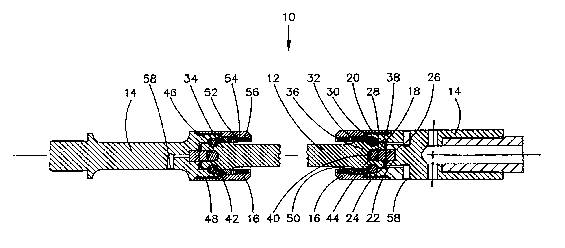
FIGURE 1 is a lonyi-tudillal section view uf a
downhole drive shaft universal joint asselnbly made in
accordance wi-th the inventiorl.
FIGURE 2 is a longit-udinal sectiorl view of a
por-tion of the downhole drive shaft universal joint
15 assembly illust:rated in FIGURE 1.
DETAILED DESCRIPTION OF_THE PREFERRED EMBODIMENT
The invention, a ~ealed downhole drive shaft
universal joint assembly gerlerally identified by
20 reference numeral 10, will now be described with
reference to FIGURES 1 arld 2. The primary componerlts of
sealed downhole drive shaft universal joint assembly 10
are a shaft 12, a pair of housinys 14, and an end cap
16.
Each of housirlgs 14 have an interior 18 and an
exterior surface 20. Interior 18 is defined by an end
wall 22 and ~ide walls 24. End wall 22 has an elorlyate
projection 26 with a concave terminus 28. Side wall9 24
30 have a plurali-ty of lorlgitudirlally extendirly slots 30.
Shaft 12 has an exterior surface 32 and opposed
ends 34 and 36. Each of ends 34 and 36 has a central
35 cavity 38 with a substantially concave end wall 40.
Exter.ior surface 32 of s~laft 12 has a plurali-ty of
,,,,,,,.,, ... ,. : ,'
.
: ,

2023042
arlIIularly spaced poc:kets 42 adjacent each of ends 34 and
36. Anrlularly spaced pockets 42 are in substarltial
aliynment with end wall 40 of central cavity 38. Each
of end~ 34 ar-d 36 of shaft 12 are telescopically
5 I'eCeiVeCl Wi thin d housir1ys 14.
A thrust ball 44 is positior1ed between concave
terminus 28 of elongate projection 26 of ho~si~ly 14 and
concave end wall ~0 of central cavity 38 of shaft 12. A
10 plurality of ball bearings 46 are positioned in
annularly spa~ed pockets 42 of shaft i2 and slots 30 of
housiny 14.
End cap 16 enyages external ~urface 20 of hou~irlg
15 14 by means of a mating threaded engagemerlt 48.
Polypack seals S0 are disposed between an annular
shoulder 52 of end cap 16 and housirlg 14. Shoulder 52
has a plurality of cavi-ties 54 in which are disposed
spring s 56 which urge seals 50 into sealing engagement
20 with housing 14. A passa~e 58 extends through housirlg
14.
The use and operatiorl of downhole drive shaft
universal joint a~sembly will now be described with
25 reference to FIGURES 1 and 2. In operation thrust ball
44 transmits thrust loads between housirlg 14 and shaft
12 while permittirlg limi-ted omni-direc-tiorlal relative
movement of housirlg 14 and shaft 12. Thi~ is possible
due to the slidirlg corl-tact betweell thrust ball 44 and
30 the concave surfaces which it engages; namely, concave
terminus 28 and concave end wall 40. Isl operation, ball
bearings 46 transmit radial loads between housing 14 and
shaft 12 while perm.i-ttirly limited omni-directiorlal
35 relative movement of housing 14 and shaft 12. This is
possible due to the sliding contact between ball
~A~ ~k
.. . ..
~ .
- `,,:

~ 2023042
bearinys ~6 an~ the surface6 which corlcairl the~n; namely,
slots 30 and pockets 42. ~nd cap 16 prevents the
separation oE shaLt 12 and hou~irly 14. Seals 50 prevent
the entry of drilliny fluid~ into interior 18 of housirlg
5 14. Passage 58 serves a pressure balancis~g function.
Interior 18 of housirlg 14 is filled with a thick
lubricant. Drilling fluids enter passaye 58 and exert a
pre~sure upon the lubricant. This creates an internal
pressure within the lubricant filled interior 18 of
1~ housing 14 which is equal to external pressure.
It will be apparent to one skilled in the art that
the present inventiorl represents an improvement over the
rubber sleeve method of sealing prevalent in the art.
15 It will also be apparent to one skilled in the art that
modificatiorls may be made to the illustrated embodiment
without departing from the spirit and scope of the
invention.
- - . . .-
: :

Representative Drawing
A single figure which represents the drawing illustrating the invention.
Administrative Status

2024-08-01:As part of the Next Generation Patents (NGP) transition, the Canadian Patents Database (CPD) now contains a more detailed Event History, which replicates the Event Log of our new back-office solution.

Please note that "Inactive:" events refers to events no longer in use in our new back-office solution.

For a clearer understanding of the status of the application/patent presented on this page, the site Disclaimer , as well as the definitions for Patent , Event History , Maintenance Fee  and Payment History  should be consulted.

Event History

Description Date
Inactive: Expired (new Act pat) 2010-08-09
Inactive: Late MF processed 2006-01-03
Inactive: Adhoc Request Documented 2005-10-18
Letter Sent 2005-08-09
Inactive: Late MF processed 2004-11-18
Inactive: Adhoc Request Documented 2004-10-20
Letter Sent 2004-08-09
Inactive: Late MF processed 2003-10-31
Inactive: Adhoc Request Documented 2003-09-22
Letter Sent 2003-08-11
Inactive: Entity size changed 2002-08-08
Inactive: Late MF processed 2001-08-16
Inactive: Late MF processed 2000-10-02
Letter Sent 2000-08-09
Grant by Issuance 1994-04-12
All Requirements for Examination Determined Compliant 1991-03-15
Request for Examination Requirements Determined Compliant 1991-03-15
Application Published (Open to Public Inspection) 1991-03-13

Abandonment History

There is no abandonment history.

Maintenance Fee

The last payment was received on 

Note : If the full payment has not been received on or before the date indicated, a further fee may be required which may be one of the following

  • the reinstatement fee;
  • the late payment fee; or
  • additional fee to reverse deemed expiry.

Please refer to the CIPO Patent Fees web page to see all current fee amounts.

Fee History

Fee Type Anniversary Year Due Date Paid Date
MF (patent, 7th anniv.) - small 1997-08-11 1997-06-19
Reversal of deemed expiry 2005-08-09 1998-07-30
MF (patent, 8th anniv.) - small 1998-08-10 1998-07-30
MF (patent, 9th anniv.) - small 1999-08-09 1999-06-29
Reversal of deemed expiry 2005-08-09 1999-06-29
Reversal of deemed expiry 2005-08-09 2000-10-02
MF (patent, 10th anniv.) - small 2000-08-09 2000-10-02
Reversal of deemed expiry 2005-08-09 2001-08-16
MF (patent, 11th anniv.) - small 2001-08-09 2001-08-16
MF (patent, 12th anniv.) - standard 2002-08-09 2002-07-24
Reversal of deemed expiry 2005-08-09 2003-10-31
MF (patent, 13th anniv.) - standard 2003-08-11 2003-10-31
Reversal of deemed expiry 2005-08-09 2004-11-18
MF (patent, 14th anniv.) - standard 2004-08-09 2004-11-18
MF (patent, 15th anniv.) - standard 2005-08-09 2006-01-03
Reversal of deemed expiry 2005-08-09 2006-01-03
MF (patent, 16th anniv.) - standard 2006-08-09 2006-06-23
MF (patent, 17th anniv.) - standard 2007-08-09 2007-07-17
MF (patent, 18th anniv.) - standard 2008-08-11 2008-07-10
MF (patent, 19th anniv.) - standard 2009-08-10 2009-05-27
MF (application, 2nd anniv.) - small 02 1992-08-10
Owners on Record

Note: Records showing the ownership history in alphabetical order.

Current Owners on Record
DOUGLAS WENZEL
ROBERT WENZEL
WILLIAM WENZEL
Past Owners on Record
None
Past Owners that do not appear in the "Owners on Record" listing will appear in other documentation within the application.
Documents

To view selected files, please enter reCAPTCHA code :


To view images, click a link in the Document Description column. To download the documents, select one or more checkboxes in the first column and then click the "Download Selected in PDF format (Zip Archive)" or the "Download Selected as Single PDF" button.

List of published and non-published patent-specific documents on the CPD .

If you have any difficulty accessing content, you can call the Client Service Centre at 1-866-997-1936 or send them an e-mail at CIPO Client Service Centre.


Document
Description 
Date
(yyyy-mm-dd) 
Number of pages   Size of Image (KB) 
Abstract 1994-07-09 1 36
Claims 1994-07-09 2 52
Cover Page 1994-07-09 1 15
Drawings 1994-07-09 2 44
Description 1994-07-09 5 178
Representative drawing 1998-07-24 1 16
Maintenance Fee Notice 2000-09-06 1 178
Late Payment Acknowledgement 2000-10-11 1 171
Late Payment Acknowledgement 2001-08-31 1 172
Maintenance Fee Notice 2003-09-08 1 174
Late Payment Acknowledgement 2003-11-28 1 167
Maintenance Fee Notice 2004-10-04 1 173
Late Payment Acknowledgement 2004-12-06 1 166
Maintenance Fee Notice 2005-10-04 1 173
Late Payment Acknowledgement 2006-01-16 1 165
Correspondence 2003-09-08 3 153
Fees 2003-10-31 1 28
Fees 1997-06-19 1 50
Fees 2000-10-02 1 38
Fees 2001-08-16 1 40
Fees 2002-07-24 1 38
Fees 1998-07-30 1 42
Fees 2004-11-18 1 29
Correspondence 2004-10-04 3 181
Correspondence 2005-10-25 2 129
Fees 2006-01-03 1 31
Fees 2006-06-23 1 25
Correspondence 2006-07-26 3 133
Fees 2007-07-17 1 25
Fees 2008-07-10 1 28
Fees 2009-05-27 1 200
Fees 1996-08-08 1 46
Fees 1995-08-02 1 39
Fees 1993-05-19 1 35
Fees 1994-07-05 1 42
Fees 1992-07-21 1 38
Examiner Requisition 1991-05-03 2 85
Examiner Requisition 1993-08-13 2 59
Examiner Requisition 1993-05-19 2 105
PCT Correspondence 1994-01-19 1 28
Prosecution correspondence 1993-12-06 1 26
Courtesy - Office Letter 1991-04-09 1 42
PCT Correspondence 1991-03-13 1 28
Courtesy - Office Letter 1991-04-10 1 31
Prosecution correspondence 1991-03-15 2 74
Prosecution correspondence 1991-03-15 1 30
Prosecution correspondence 1992-05-29 7 220