Sélection de la langue

Search

Sommaire du brevet 2023042 

Énoncé de désistement de responsabilité concernant l'information provenant de tiers

Une partie des informations de ce site Web a été fournie par des sources externes. Le gouvernement du Canada n'assume aucune responsabilité concernant la précision, l'actualité ou la fiabilité des informations fournies par les sources externes. Les utilisateurs qui désirent employer cette information devraient consulter directement la source des informations. Le contenu fourni par les sources externes n'est pas assujetti aux exigences sur les langues officielles, la protection des renseignements personnels et l'accessibilité.

Disponibilité de l'Abrégé et des Revendications

L'apparition de différences dans le texte et l'image des Revendications et de l'Abrégé dépend du moment auquel le document est publié. Les textes des Revendications et de l'Abrégé sont affichés :

  • lorsque la demande peut être examinée par le public;
  • lorsque le brevet est émis (délivrance).
(12) Brevet: (11) CA 2023042
(54) Titre français: JOINT A CARDAN POUR ARBRE D'ENTRAINEMENT DE MOTEUR ETANCHE A FOND DE FORAGE
(54) Titre anglais: SEALED DOWNHOLE MOTOR DRIVE SHAFT UNIVERSAL JOINT ASSEMBLY
Statut: Durée expirée - au-delà du délai suivant l'octroi
Données bibliographiques
(51) Classification internationale des brevets (CIB):
  • E21B 4/00 (2006.01)
(72) Inventeurs :
  • WENZEL, DOUGLAS (Canada)
  • WENZEL, ROBERT (Canada)
  • WENZEL, WILLIAM (Canada)
(73) Titulaires :
  • DOUGLAS WENZEL
  • ROBERT WENZEL
  • WILLIAM WENZEL
(71) Demandeurs :
(74) Agent: DOUGLAS B. THOMPSONTHOMPSON, DOUGLAS B.
(74) Co-agent:
(45) Délivré: 1994-04-12
(22) Date de dépôt: 1990-08-09
(41) Mise à la disponibilité du public: 1991-03-13
Requête d'examen: 1991-03-15
Licence disponible: S.O.
Cédé au domaine public: S.O.
(25) Langue des documents déposés: Anglais

Traité de coopération en matière de brevets (PCT): Non

(30) Données de priorité de la demande: S.O.

Abrégés

Abrégé anglais


ABSTRACT OF THE DISCLOSURE
A Sealed Downhole Motor Drive Shaft Universal Joint
Assembly consisting of a housing with an interior and an
exterior surface. The interior has an end wall and side
walls. The end wall has an elongate projection with a
concave terminus. The side walls have a plurality of slots.
A shaft is provided having an exterior surface and opposed
ends. Each of the ends has a central cavity with a
substantially concave end wall. The exterior surface of the
drive shaft has a plurality of annularly spaced pockets
adjacent each end. The pockets are in substantial alignment
with the end wall of the central cavity. Each end of the
drive shaft is telescopically received within one of the
housings. A thrust ball is positioned between the concave
terminus of the elongate projection of the housing and the
concave end wall of the central cavity of the shaft thereby
transmitting thrust loads between the housing and the shaft
while permitting omni-directional relative movement of the
housing and the shaft. A plurality of ball bearings are
positioned in the pockets of the shaft and the slots of the
housing thereby transmitting radial loads between the housing
and the shaft while permitting omni-directional relative
movement of the housing and the shaft. An end cap engages
the external surface of the housing thereby preventing the
separation of the shaft and the housing. Seals are disposed
between the end cap and the housing to prevent the entry of
drilling fluids into the housing.

Revendications

Note : Les revendications sont présentées dans la langue officielle dans laquelle elles ont été soumises.


THE EMBODIMENTS OF THE INVENTION IN WHICH AN EXCLUSIVE PROPERTY
OR PRIVILEGE IS CLAIMED ARE DEFINED AS FOLLOWS:
1. A Sealed Downhole Motor Drive Shaft Universal Joint Assembly,
comprising:
a. a housing with an interior and an exterior surface, the
interior having an end wall and side walls, the end wall having
an elongate projection with a concave terminus, the side walls
having a plurality of slots;
b. a shaft with an exterior surface and opposed ends, each
of the ends having a central cavity with a substantially concave
end wall, the exterior surface of the drive shaft having a
plurality of radially spaced pockets adjacent each end in
substantial alignment with the end wall of the central cavity,
the drive shaft being telescopically received within the housing
with the central cavity in axial alignment with the elongate
projection in the housing;
c. a thrust ball positioned between the concave terminus
of the elongate projection of the housing and the concave end
wall of the central cavity of the shaft thereby transmitting
thrust loads between the housing and the shaft while permitting
limited omni-directional relative movement of the housing and the
shaft;
d. a plurality of ball bearings positioned in the radially
spaced pockets of the shaft and the slots of the housing thereby
transmitting radial loads between the housing and the shaft while
permitting limited omni-directional relative movement of the
housing and the shaft;
e. an annular end cap engages the exterior surface of the
housing, the end cap engaging the end of the shaft upon an axial
force being exerted thereby preventing the axial separation of
the shaft and the housing;
f. seals disposed between the end cap and the housing to
prevent the entry of drilling fluids into the housing; and
g. a passage extending from the housing exterior surface
through the housing to the housing end wall, for continuously
allowing, in use, drilling fluids to enter the passage thereby

creating an internal pressure within the lubricant filled
interior of the housing which is equal to pressure external of
the universal joint housing.

Description

Note : Les descriptions sont présentées dans la langue officielle dans laquelle elles ont été soumises.

~`~ 2~2~
: .
THe pres~rJI: inverlt;oiJ I~l~te~i to ~ Seale(3 Dov~rlllole
Motor Drive Shaft Universal Joint Assembly.
BAC~GROUND OF THE INVENTION
, 5 Tlle output shaft of a Dowrlhole motcr used wit~lin
-~ the oil industry for earth borirly operations moves in an
;~ eccell-tric fashiorl. This eccelltric movemerlt must be
converted into a concerltric movement for the drill bit
to perform its intended functiorl. At -the present time
10 thi~ conversion is accomplished by means of a drive
s~laf-t havirly universal joint connectiorls which connects
the downhole motor to a bearing assembly rotating the
drill bit,
The penetration of abrasive drilling fluids into
the drive shaft universal joint assembly has an adverse
effect on the operational life of the drive shafts. In
order to prolong this operational life, attempts have
been made to seal the universal joint assernblies. The
¦20 universal joirlt as9emblies of most drive shafts do not
,~readily lend t~lemselves to sealiny. It has therefore
come to be the practise to secure a lubricant filled
¦rubber sleeve over the universal joint. This sleeve has
a number of recogniYed disadvantages. It is common for
25 it to slide out of positiorl, where it can become damaged
80 it no longer serves its interlded function, or can
move into a position where it interferes with drilliny
operations.
30 SUMMARY OF THE INVENTION
What is required is a sealed d;rive shaft universal
joint assembly.
According to the invention there is provided a
Sealed Downhole Motor Drive Shaft Universal Joint
' . :, '. ' '
: ~' '', , .
' ' ,
. ' .
' ' ~ ' .

~ 2023042
., ~
A';~ y, wn:ich iS cc~mLJr:ic;ed o.F a holl6irlg with an
irl-terior and arl exterior surface. T~le interior ha~ an
en~ wall arl~ sicle walls. The end wall ha~ an elorlgate
I pro jec~ion with d ~ollcave termirlus. The side walls have
a plural;-ty of ~loL~. A shaft is provi~ed ~lavirlc3 an
exterior surface and opposed encls. Each of the ends has
a central cavity with a ~ub~tantially concave e~ld wall.
The exterior ~urIace of the drive snaft has a plurality
of anrlularly spaced pockets adjacellt each eJl~. The
,,10 pocket~ are in substantial alignment with the end wall
of the central cavity. Each end o~ the drive shaft is
telescopically received withi~ one of the housings. A
thrust ball ;s po~itioned between the concave termirlu6
of the elongate projectioil of the housirlg and the
lS concave end wall of the central cavity of the shaf-t
thereby trarlsmittirly thrust loads between the housirlg
and the shaft while permit-ting limited omni-directiorlal
relative movement of the housirlg and the shaft. A
plurality of hall bearinys are positioned in the
20 annularly spaced pockets of the shaft and the arcuate
slo-ts of the housirly thereby trarlsmittirly radial ~.oads
between the housing and the shaft while permittiny omni-
directional relative movement of the housiny and the
shaft. An end cap enyages the external ~urface of the
25 housing thereby preverltirlg the separation of -the shaft
and the housing. Seals are disposed between -the end cap
and the housing to preverl-t the entry oE drill:irlg Eluids
into the housirlg.
Although beneficial results may be obtairled throuyh
the use of the drive shaft universal joint assembly as
described, seal wear occurs whenever the pressures on
opposite faces of a seal are unequal. Even more
35 berleficial results may therefore be obtairled by havirlg a
passage extending though the housing such that drilling
~ .

~ 2023042
fluids e;lter the passage -th~:reby creatiny arl interrlal
presYure withirl the lubricarl-t filled in~e-rior of the
hOUsi.rly which is equal to ex-ternal E~ressur~.
BRIEF DESCRIPTION OF THE DRAWINGS
These and other features of the invention will
become more appa:rerlt from the following description in
which reference is made to the appended drawing~,
whereirl:
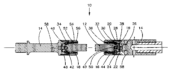
FIGURE 1 is a lonyi-tudillal section view uf a
downhole drive shaft universal joint asselnbly made in
accordance wi-th the inventiorl.
FIGURE 2 is a longit-udinal sectiorl view of a
por-tion of the downhole drive shaft universal joint
15 assembly illust:rated in FIGURE 1.
DETAILED DESCRIPTION OF_THE PREFERRED EMBODIMENT
The invention, a ~ealed downhole drive shaft
universal joint assembly gerlerally identified by
20 reference numeral 10, will now be described with
reference to FIGURES 1 arld 2. The primary componerlts of
sealed downhole drive shaft universal joint assembly 10
are a shaft 12, a pair of housinys 14, and an end cap
16.
Each of housirlgs 14 have an interior 18 and an
exterior surface 20. Interior 18 is defined by an end
wall 22 and ~ide walls 24. End wall 22 has an elorlyate
projection 26 with a concave terminus 28. Side wall9 24
30 have a plurali-ty of lorlgitudirlally extendirly slots 30.
Shaft 12 has an exterior surface 32 and opposed
ends 34 and 36. Each of ends 34 and 36 has a central
35 cavity 38 with a substantially concave end wall 40.
Exter.ior surface 32 of s~laft 12 has a plurali-ty of
,,,,,,,.,, ... ,. : ,'
.
: ,

2023042
arlIIularly spaced poc:kets 42 adjacent each of ends 34 and
36. Anrlularly spaced pockets 42 are in substarltial
aliynment with end wall 40 of central cavity 38. Each
of end~ 34 ar-d 36 of shaft 12 are telescopically
5 I'eCeiVeCl Wi thin d housir1ys 14.
A thrust ball 44 is positior1ed between concave
terminus 28 of elongate projection 26 of ho~si~ly 14 and
concave end wall ~0 of central cavity 38 of shaft 12. A
10 plurality of ball bearings 46 are positioned in
annularly spa~ed pockets 42 of shaft i2 and slots 30 of
housiny 14.
End cap 16 enyages external ~urface 20 of hou~irlg
15 14 by means of a mating threaded engagemerlt 48.
Polypack seals S0 are disposed between an annular
shoulder 52 of end cap 16 and housirlg 14. Shoulder 52
has a plurality of cavi-ties 54 in which are disposed
spring s 56 which urge seals 50 into sealing engagement
20 with housing 14. A passa~e 58 extends through housirlg
14.
The use and operatiorl of downhole drive shaft
universal joint a~sembly will now be described with
25 reference to FIGURES 1 and 2. In operation thrust ball
44 transmits thrust loads between housirlg 14 and shaft
12 while permittirlg limi-ted omni-direc-tiorlal relative
movement of housirlg 14 and shaft 12. Thi~ is possible
due to the slidirlg corl-tact betweell thrust ball 44 and
30 the concave surfaces which it engages; namely, concave
terminus 28 and concave end wall 40. Isl operation, ball
bearings 46 transmit radial loads between housing 14 and
shaft 12 while perm.i-ttirly limited omni-directiorlal
35 relative movement of housing 14 and shaft 12. This is
possible due to the sliding contact between ball
~A~ ~k
.. . ..
~ .
- `,,:

~ 2023042
bearinys ~6 an~ the surface6 which corlcairl the~n; namely,
slots 30 and pockets 42. ~nd cap 16 prevents the
separation oE shaLt 12 and hou~irly 14. Seals 50 prevent
the entry of drilliny fluid~ into interior 18 of housirlg
5 14. Passage 58 serves a pressure balancis~g function.
Interior 18 of housirlg 14 is filled with a thick
lubricant. Drilling fluids enter passaye 58 and exert a
pre~sure upon the lubricant. This creates an internal
pressure within the lubricant filled interior 18 of
1~ housing 14 which is equal to external pressure.
It will be apparent to one skilled in the art that
the present inventiorl represents an improvement over the
rubber sleeve method of sealing prevalent in the art.
15 It will also be apparent to one skilled in the art that
modificatiorls may be made to the illustrated embodiment
without departing from the spirit and scope of the
invention.
- - . . .-
: :

Dessin représentatif
Une figure unique qui représente un dessin illustrant l'invention.
États administratifs

2024-08-01 : Dans le cadre de la transition vers les Brevets de nouvelle génération (BNG), la base de données sur les brevets canadiens (BDBC) contient désormais un Historique d'événement plus détaillé, qui reproduit le Journal des événements de notre nouvelle solution interne.

Veuillez noter que les événements débutant par « Inactive : » se réfèrent à des événements qui ne sont plus utilisés dans notre nouvelle solution interne.

Pour une meilleure compréhension de l'état de la demande ou brevet qui figure sur cette page, la rubrique Mise en garde , et les descriptions de Brevet , Historique d'événement , Taxes périodiques et Historique des paiements devraient être consultées.

Historique d'événement

Description Date
Inactive : Périmé (brevet - nouvelle loi) 2010-08-09
Inactive : TME en retard traitée 2006-01-03
Inactive : Demande ad hoc documentée 2005-10-18
Lettre envoyée 2005-08-09
Inactive : TME en retard traitée 2004-11-18
Inactive : Demande ad hoc documentée 2004-10-20
Lettre envoyée 2004-08-09
Inactive : TME en retard traitée 2003-10-31
Inactive : Demande ad hoc documentée 2003-09-22
Lettre envoyée 2003-08-11
Inactive : Grandeur de l'entité changée 2002-08-08
Inactive : TME en retard traitée 2001-08-16
Inactive : TME en retard traitée 2000-10-02
Lettre envoyée 2000-08-09
Accordé par délivrance 1994-04-12
Toutes les exigences pour l'examen - jugée conforme 1991-03-15
Exigences pour une requête d'examen - jugée conforme 1991-03-15
Demande publiée (accessible au public) 1991-03-13

Historique d'abandonnement

Il n'y a pas d'historique d'abandonnement

Taxes périodiques

Le dernier paiement a été reçu le 

Avis : Si le paiement en totalité n'a pas été reçu au plus tard à la date indiquée, une taxe supplémentaire peut être imposée, soit une des taxes suivantes :

  • taxe de rétablissement ;
  • taxe pour paiement en souffrance ; ou
  • taxe additionnelle pour le renversement d'une péremption réputée.

Veuillez vous référer à la page web des taxes sur les brevets de l'OPIC pour voir tous les montants actuels des taxes.

Titulaires au dossier

Les titulaires actuels et antérieures au dossier sont affichés en ordre alphabétique.

Titulaires actuels au dossier
DOUGLAS WENZEL
ROBERT WENZEL
WILLIAM WENZEL
Titulaires antérieures au dossier
S.O.
Les propriétaires antérieurs qui ne figurent pas dans la liste des « Propriétaires au dossier » apparaîtront dans d'autres documents au dossier.
Documents

Pour visionner les fichiers sélectionnés, entrer le code reCAPTCHA :


Pour visualiser une image, cliquer sur un lien dans la colonne description du document. Pour télécharger l'image (les images), cliquer l'une ou plusieurs cases à cocher dans la première colonne et ensuite cliquer sur le bouton "Télécharger sélection en format PDF (archive Zip)" ou le bouton "Télécharger sélection (en un fichier PDF fusionné)".

Liste des documents de brevet publiés et non publiés sur la BDBC .

Si vous avez des difficultés à accéder au contenu, veuillez communiquer avec le Centre de services à la clientèle au 1-866-997-1936, ou envoyer un courriel au Centre de service à la clientèle de l'OPIC.


Description du
Document 
Date
(aaaa-mm-jj) 
Nombre de pages   Taille de l'image (Ko) 
Abrégé 1994-07-09 1 36
Revendications 1994-07-09 2 52
Page couverture 1994-07-09 1 15
Dessins 1994-07-09 2 44
Description 1994-07-09 5 178
Dessin représentatif 1998-07-24 1 16
Avis concernant la taxe de maintien 2000-09-06 1 178
Quittance d'un paiement en retard 2000-10-11 1 171
Quittance d'un paiement en retard 2001-08-31 1 172
Avis concernant la taxe de maintien 2003-09-08 1 174
Quittance d'un paiement en retard 2003-11-28 1 167
Avis concernant la taxe de maintien 2004-10-04 1 173
Quittance d'un paiement en retard 2004-12-06 1 166
Avis concernant la taxe de maintien 2005-10-04 1 173
Quittance d'un paiement en retard 2006-01-16 1 165
Correspondance 2003-09-08 3 153
Taxes 2003-10-31 1 28
Taxes 1997-06-19 1 50
Taxes 2000-10-02 1 38
Taxes 2001-08-16 1 40
Taxes 2002-07-24 1 38
Taxes 1998-07-30 1 42
Taxes 2004-11-18 1 29
Correspondance 2004-10-04 3 181
Correspondance 2005-10-25 2 129
Taxes 2006-01-03 1 31
Taxes 2006-06-23 1 25
Correspondance 2006-07-26 3 133
Taxes 2007-07-17 1 25
Taxes 2008-07-10 1 28
Taxes 2009-05-27 1 200
Taxes 1996-08-08 1 46
Taxes 1995-08-02 1 39
Taxes 1993-05-19 1 35
Taxes 1994-07-05 1 42
Taxes 1992-07-21 1 38
Demande de l'examinateur 1991-05-03 2 85
Demande de l'examinateur 1993-08-13 2 59
Demande de l'examinateur 1993-05-19 2 105
Correspondance reliée au PCT 1994-01-19 1 28
Correspondance de la poursuite 1993-12-06 1 26
Courtoisie - Lettre du bureau 1991-04-09 1 42
Correspondance reliée au PCT 1991-03-13 1 28
Courtoisie - Lettre du bureau 1991-04-10 1 31
Correspondance de la poursuite 1991-03-15 2 74
Correspondance de la poursuite 1991-03-15 1 30
Correspondance de la poursuite 1992-05-29 7 220