Note: Descriptions are shown in the official language in which they were submitted.
2~3283
ELEVATOR POWER SOURCE DEVICE
~echnical Field
This invention relates to electric motive power systems
for elevators and, more particularly, to such systems
utili~ing auxiliary power.
Background Art
An elevator power source device may include a speed
control unit which receives a power supply from a commercial
power source and which can adjust the commercial utility
line frequency at will for controlling the speed, and may
further include an emergency power supply unit which
provides power when the power supply from the commercial
power source is stopped, e.g., during power failure. This
invention concerns this type of elevator power source
device.
Figure 2 shows a conventional elevator power device of
this type. In Fig. 2, a power source monitoring relay 1 is
connected to power lines (three-phase, 200/400 V) for
providing fixed frequency power from the commercial power
source. An AC-DC converter 2 has its input side connected
to the commercial power lines and is used for providing DC.
A DC-AC inverter 3 has its input side connected to the DC
output side of the AC-DC converter 2 and provides AC for
controlling an elevator motor 4. A set of batteries 5 is
connected to the output side of AC-DC converter 2 via a set
of normally closed contacts (which will be closed, i.e.,
short circuited, during power failure and otherwise open) of
power source monitoring relay 1. A battery charger 6 is
connected to the power lines via normally open contacts
(which will ~e closed under normal conditions and open
circuited during power failure) of power source monitoring
relay 1. A DC-AC inverter 7, which, together with a step-
-- 1 --
2023283
up DC reactor (DCL) and a switching unit S connected to it,form an emergency power generating device.
AC reactors ACL are connected to prevent a current
surge on the input side of AC-DC converter 2 for controlling
the elevator motor and the output side of DC-AC inverter 3.
A large-capacitance capacitor C is connected to the input
side of DC-AC inverter 3 for controlling the motor. In this
way, a voltage source that can guarantee a constant voltage
is formed.
The operation is as follows. When the commercial power
is supplied, the AC-DC converter 2 supplies DC power to
capacitor C on a DC link. The DC link power is converted to
AC power with a variable frequency by the DC-AC converter 3.
This frequency-variable AC power is supplied to motor 4,
which is driven with its speed controlled. For this power
supply system, when motor 4 is driven mechanically by the
elevator system's counterweight, it can act as a generator
with the electrical power generated by it fed back to the
power source side. With the power feedback system, the
operation efficiency can be improved.
In addition, the commercial power is also used as the
power for the elevator control device, and it is used for
open/close control of the elevator door, operation of signal
device, etc.
In using the commercial electrical power, battery
charger 6 always charges battery 5.
During power failure, by a make/break operation of the
related contacts NP of power source monitoring relay 1, AC-
DC converter 2 and battery charger 6 are cut off from the
power lines, and battery 5 is connected via the DC link to
the DC-AC inverter 3 for controlling the motor. With the
aid of the power supplies from battery 5, the driving of
motor 4 is continued until the cage reaches the nearest
story. The power from battery 5 is supplied to the elevator
~ 21)~32~3
control devices via the emergency power generating device,
so that there is no break in the control operation.
Although such a conventional elevator power system can
certainly operate satisfactorily, it nevertheless uses three
sets of converters and inverters. Among them, two sets 2, 7
are not used during normal power supply or in power failure.
The design efficiency is therefore poor. This is a cost
problem.
Disclosure of ~nvention
The object of the present invention is to provide a
type of elevator power system having a simplified structure.
According to the present invention, an AC-DC converter
is used both to convert AC to DC during normal operation and
to convert stored DC power to AC during power failures.
In further accord with the present invention, an
elevator power system comprises a power source monitoring
relay connected to the power lines supplying power from a
commercial power source, an AC-DC converter which has its
input side connected to said power lines, a DC-AC inverter
which has its input side connected to the output side of
said AC-DC converter and is used to control a motor, a set
of batteries which is connected to the output side of said
AC-DC converter via normally closed contacts (open circuited
during normal operation but closed during power failure) of
said power source monitoring relay, a battery charger which
is connected to said power lines via normally open (during
power failure) contacts of said power source monitoring
relay,
In still further accord with the present invention, a
step-up transformer is connected to the input side of said
AC-DC converter via normally closed (during power failure)
contacts of said source monitoring relay, and which
generates a control voltage for elevator control devices.
20,~3283
-
In still further accord with the present invention, a
switch circuit is responsive to said power source monitoring
relay for providing control signals to the transistors of
the AC-DC converter in the absence power failure so that
said AC-DC converter operates as an AC-DC converter, and for
providing control signals to the transistors of said AC-DC
converter during power failure so that said AC-DC converter
operates as a DC-AC inverter.
These and other objects, features and advantages of the
present invention will become more apparent in light of the
following detailed description of a best mode embodiment
thereof, as illustrated in the accompanying drawings.
Brief Description of the Drawing~
Fig. 1 is a circuit diagram of an elevator system
having backup power arranged according to teachings of the
present invention; and
Fig. 2 is a circuit diagram of a prior art backup power
arrangement.
Best Node for Carrying out the Invention
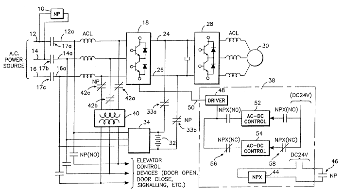
Fig. 1 shows a preferred embodiment of the present
invention. A power source monitoring relay 10 is connected
to two power lines 12, 14 of three power lines 12, 14, 16
for supplying three phase power from a commercial utility
power source to an AC-DC converter 18 having its input side
connected to power lines 12a, 14a, 16a through normally open
contacts 17a, 17b, 17c of relay 10 and through AC reactors
(ACL) and having its output connected to a DC link 24, 26.
A DC-AC inverter 28 is connected to the DC link 24, 26 and
provides AC for controlling a motor 30. A battery 32 is
connected to the DC link via a pair of normally closed (open
circuited during normal operation and closed during a power
failure) contacts 33a, 33b of the power source monitoring
relaylO. A battery charger 34 is connected to AC power
-- 4
20?3283
-
lines 12, 14, 16 via contacts 17a, 17b, 17c (during normal
conditions) of power source monitoring relaylO. A
conversion switch circuit 38 provides control signals to
device 18. A step-up transformer 40 is connected to the
input side of the AC-DC converter 18 via normally closed
(during power failure) contacts 42a, 42b, 42c of the power
source monitoring relay and generates the elevator control
voltage for the elevator control devices. Much of the the
explanation for the structural elements which are the same
as those in the power source device shown in Fig. 2 will not
be repeated here.
Conversion switch circuit 38 is connected to power
source monitoring relay 10 and AC-DC converter 18.
Conversion switch circuit 38 comprises a power source
monitoring auxiliary relay 44 connected to a normally open
(closed during normal power supply and open-circuited during
a power failure) contact 46 of power source monitoring relay
10, a transistor driving circuit 48 for providing control
signals on a line 50 to AC-DC converter 18, an AC-DC
converter control circuit 52 for use during normal
operational condition of the utility power supply and
connected to a power source, e.g., DC 24 V, and an AC-DC
converter control circuit 54 for use during power failure
for providing control signals on the line 50 via the
transistor driving circuit 48 via a pair of normally closed
(during power failure of auxiliary relay 44) contacts 56,
58.
When power is supplied from commercial power lines,
conversion switch circuit 38 has its AC-DC converter control
circuit 52 for normal power supply connected to the device
18 via normally open contacts NPX (NO) of power source
monitoring auxiliary relay 44, and transistor driving
circuit 48 controls the transistors of device 18 so that it
operates as an AC-DC converter. In this case, the operation
of the device shown in Fig. 1 becomes identical to the
-- 5
2023283
operation of the device shown in Fig. 2. Now, let us look
at the operation of the device shown in Fig. 1 in the case
of power failure.
During power failure, conversion switch circuit 38 has
its AC-DC converter control circuit 54 for the case of power
failure connected to the 24 V DC power source via normally
closed contacts NPX (NC) of power source monitoring
auxiliary relay 44, and transistor driving circuit 48
controls the transistors of device 18 so that device 18
operates as a DC-AC inverter. Also, during
power failure, battery 32 supplies power to DC-AC inverter
28 for controlling the motor via the normally closed
contacts 33a, 33b (during power failure), and drives motor
30. At the same time, battery 32 supplies DC power to AC-DC
converter 28 via the contacts 33a, 33b (during power
failure); the AC voltage converted from said DC power under
the control of conversion switch circuit 38 is stepped up to
the normal AC control voltage by step-up transformer 40 via
the contacts 42a, 42b, 42c (during power failure), and is
supplied to the elevator control devices.
As explained above, while a conventional elevator power
source device requires three sets of converters or
inverters, the power source device of this invention only
has two sets, which operate without interruption in both
normal power supply state and during power failure. In this
way, the structure of the power source device can be
simplified by the design teachings of the present
disclosure, which can be used with a higher efficiency in
this case.
Although the invention has been shown and described
with respect to a best mode embodiment thereof, it should be
understood by those skilled in the art that the foregoing
and various other changes, omissions, and additions in the
form and detail thereof may be made therein without
departing from the spirit and scope of the invention.
- 6 -
. .
B