Note: Descriptions are shown in the official language in which they were submitted.
MB084731328
2023331
PATENT APPLICATION
TITLE: A PRESS SECTION APPARATUS
BACKGROUND OF THE INVENTION:
FIELD OF THE INVENTION:
The present invention relates to a press section
apparatus definir.g a press nip for pressing a web of paper.
More particularly, the present invention relates to a press
section apparatus in which the backing roll includes a
granite outer surface.
INFORMATION DISCLOSURE STATEMENT:
Although many attempts have been made at manufacturing
artificial granite press rolls, the inherent quality of
granite when fabricated as a press roll is unable to be
duplicated by artificial means.
More particularly, the surface texture of a granite roll
is such that after passing a formed web through a press nip
defined by a press member and a rotatable granite backing
roll, the resultant pressed web is easily removed from the
surface of the granite backing roll. However,-although
granite press rolls possess ideal release characteristics,
they are unable to withstand bowing along the axial length
thereof because unlike their counterpart steel rolls, granite
backing rolls have a very low tensile strength. Therefore,
according to the present invention, a granite backing roll
--1--
MB084731328
2û~33I
includes deflection compensating means so that bowing of the
granite roll is inhibited.
More specifically, for certain grades of paper, the
desirable release characteristics exhibited by natural
granite cannot be duplicated by manufactured materials. Due
to the engineering strength limitations of the granite,
conventional granite roll designs are not suitable for use in
high nip pressure configurations which can be up to pressures
of 6,000 pounds per linear inch.
A solution to the aforementioned problem is to use a
granite shell or a composite shell including a metal support
and an overlying sleeve of granite so that the external
applied nip load is directly opposed by an internal load on
the shell or sleeve to minimize bending and circumferential
stresses on the granite.
The aforementioned concept has been used for metal
shelled rolls in the prior art but has not been used for
rolls which have a granite shell or sleeve.
The proposed granite roll would allow the application of
high nip presses such as extended nip presses to grades that
require granite roll surfaces for necessary sheet release
characteristics.
The roll according to the present invention includes the
basic deflection compensating means of a stationary center
--2--
MB084731328
26 ~3 331
shaft which uses one or more load shoes of hydrodynamic or
hydrostatic design to apply internal pressure to the inside
diameter of a natural granite shell or a metallic shell or
support on which a granite sleeve has been mounted.
The internal shoes or pistons are loaded by hydraulic
pressure against the inside diameter of the shell in order to
oppose external loads applied to the roll.
A fluid is introduced inside the roll to pro~ide
lubrication between the stationary load shoes or pistons and
the rotating internal surface of the roll.
The internal hydraulic load pressure is controlled such
that the load opposes the external load so that the stresses
in the granite shell are kept to a minimum.
Such an arrangement allows the use of a granite roll in
an externally loaded application that has not been possible
with current granite roll designs.
The deflection compensating pistons can provide a
uniform internal pressure along the full length in a
cross-machine direction of the shell or such pistons may be
segmented to provide variable pressures in either the
cross-machine or the machine direction.
In one embodiment of the present invention, the granite
sleeve is mounted on a metal support and end rings are used
MB084731328
- 2~23331
to place the granite sleeve in compression.
Since granite has very little tensile strength, it is
normally put into compression so that during operation, the
granite will not be subject to any tensile stresses.
Alternatively, according to another embodiment of the
present invention, the backing rcll includes opposing end
plates with spaced holes axially drilled therethrough and a
plurality of tie rods extending through corresponding spaced
holes disposed axially through the granite shell so that when
the tie rods are adjusted to compress the end plates, the
granite shell is put into compression and is reinforced by
the tie rods.
In either of the aforementioned embodiments, the backing
roll may be driven or nondriven.
Therefore, a primary objective of the present invention
is to provide a press section apparatus wherein a backing
roll includes at least an outer surface of natural granite
and deflection compensating means within the backing roll for
compensating for any deflection between the shell and the
press member.
Another object of the present invention is the provision
of a press section apparatus which includes an extended nip
press shoe and a backing roll having a granite sleeve and
deflection compensating means for compensating for relative
MB084731328
2023331
deflection between the sleeve and the shoe.
Another object of the present invention is the provision
of a press section apparatus including a press member which
includes a hydrodynamic shoe which cooperates with a backing
roll which includes a shell defining an outer granite
surface.
Another object of the present invention is the provision
of a press section apparatus which includes a press member
having a hydrostatic shoe wherein the backing roll includes a
shell which defines a granite outer surface and a deflection
compensating means for compensating for any relative
deflection between the shell and the press member during
passage of the web through the press nip.
Another object of the present invention is the provision
of a press section apparatus including an ENP shoe and a
backing roll of granite wherein the granite backing roll has
deflection compensating means controlled such that during
use, pressure exerted by the shoe is counteracted by a
deflection compensating means and in the event of ar.y failure
in the hydraulic pressure line of the deflection compensating
means, the supply of hydraulic pressure to the press shoe is
simultaneously released.
Other objects and advantages of the present invention
will be apparent to those skilled in the art by consideration
of the detailed description and the annexed drawings.
MB084731328
~333:~
SUMMARY OF THE INVENTION:
The present invention relates to a press section
apparatus wherein the apparatus defines a press nip for
pressing a web of paper. The apparatus includes a frame and
a press member secured to the frame. A backing roll is
rotatably secured to the frame with the backing roll
cooperating with the press member for defining thereketween
the press nip. The backing roll also includes a shaft which
has a first and a second end. The ends of the shaft are
secured to the frame and a shell defines a granite outer
surface. The shell is disposed substantially coaxially
relative to and around the shaft with the shell being
rotatable relative to the shaft. A deflection compensating
means compensates for any relative deflection between the
shell and the press member during passage of the web through
the press nip.
In a more specific embodiment of the present invention,
the press member is a press roll.
In another embodiment of the present invention, the
press member also includes a press shoe and a movable blanket
which is disposed between the shoe and the granite surface
such that the blanket moves with the web through the press
nip.
In one embodiment of the present invention, the press
shoe is a hydrodynamic shoe and in another embodiment of the
MB084731328
`- 2G2~331
invention the press shoe is a hydrostatic shoe.
In the hydrodynamic embodiment of the present invention,
the press member also includes a housing which defines a
cylindrical cavity. The cavity is connected to a source of
pressurized fluid and a control means controls a flow of
pressurized fluid to the cavity. The shoe is slidably
disposed within the cavity such that when the control means
is in an operative first position thereof, the shoe is urged
towards the granite surface for pressing the web during
passage of the web through the press nip. When the control
means is in an inoperative second position thereof, a flow of
the pressurized fluid to the cavity is inhibited.
In one embodiment of the present invention, a first and
second bearing are disposed between the shaft and the shell
with the first and second bearings being disposed adjacent to
the first and second ends of the shaft respectively for
rotatably supporting the shell relative to the shaft.
- The shell also includes a granite sleeve which is
disposed substantially coaxially relative to the shaft and
around the shaft such that the web is pressed between the
sleeve and the press member during passage of the web through
the press nip so that deflection of the sleeve relative to
the press member is compensated for. Also, a cylindrical
metal support is disposed coaxially within the sleeve for
supporting the sleeve.
MB084731328
2~331
In another embodiment of the present invention, a layer
of resin binder is disposed between the sleeve and the
support for bonding the granite sleeve to the support.
In a further embodiment of the present invention, the
shell also includes a first and a second ring threadably
cooperating with the metal support adjacent to the first and
the second ends of the shaft respectively. The first and
second end rings define respectively a first and second
tapered face for cooperating with a first and second tapered
ends respectively defined by the granite sleeve such that
when the rings are threadably rotated towards each other, the
sleeve is compressed and urged into close conformity with the
metal support.
In another embodiment of the present invention, the
backing roll also includes a first and a second end plate.
The plates define a first and a second plurality of
circumferentially spaced holes which extend axially through
the plates respectively. A plurality of tie rods extend
through the radial holes and through a further plurality of
corresponding radially disposed holes extending axially
through the shell such that the first and second plurality of
holes and the further plurality of holes are aligned so that
when the tie rods extend through the holes and are tightened,
the end plates support and compress the shell which is of
granite.
In one embodiment of the present invention, the
MB084731328
2~33~
deflection compensating means also includes at least one
piston which is disposed between the shaft and the shell in
the vicinity of the press nip. The shaft defines at least
one bore for the slidable reception therein of the piston.
The bore is connected to a source of pressurized fluid.
Control means controls a flow of pressurized fluid into the
bore such that when the control means is disposed in a first
operative position thereof, the fluid flows into the bore for
urging the piston along the bore towards the press member.
Such compensating means compensates for deflection between
the shell and the press member. When the control means is
disposed in a second inoperative position thereof, the flow
of fluid to the bore is cut off.
In a further modification of the present invention, the
control means also controls a current of the pressurized
fluid such that when the control means is disposed in a first
position thereof, the shoe and the piston are urged towards
each other and an equal pressure is applied within the cavity
and the bore so that deflection between the shell and the
press member is compensated for, and when the control means
is in a second position thereof, pressure within both the
cavity and the bore are simultaneously released for
inhibiting any radial stress between the press member and the
shell.
The present invention is not limited to the embodiments
described in the detailed description or as shown in the
annexed drawings. Rather, the present invention is defined
- . -
MB084731328
~23~31
by the appended claims and many modifications and variationsof the present invention will be apparent to those skilled in
the art by a consideration of the description of the
preferred embodiment.
Included in such modifications would be the provision of
a crown-compensated roll having a linear piston including a
plurality of individually slidable segments. In the
provision of such linear piston or pistons, such would be of
generally rectangular configuration slidably disposed within
corresponding rectangular-shaped linear grooves extending in
a cross-machine direction.
Additionally, it will be understood by those skilled in
the art that by the provision of a crown-compensated roll
having diametrically opposed pistons, such pistons on one
side permit application of pressure to the web extending
through the pressing nip whereas the diametrically opposed
pistons assist in the separation of the crown-compensated
roll in order to allow changing of the felt and ancillary
equipment.
BRI EF DES CRIPTION OF THE DRAWINGS:
Figure 1 is a fragmentary sectional view through the
press section apparatus according to the present invention;
Figure 2 is a sectional view taken on line 2-2 of Figure
1 ; .
--10--
MB084731328
2~23331
Figure 3 is a fragmentary sectional view of an
alternative embodiment of the present invention in which the
press member is a hydrodynamic extended nip shoe;
Figure 4 is a fragmentary sectional view showing an
alternative embodiment of the present invention in which the
press member is a hydrostatic shoe;
Figure 5 is an alternative embodiment of the present
invention which includes end plates and tie rods; and
Figure 6 is a sectional view taken on the line 6-6 of
Figure 5.
Similar reference characters refer to similar parts
throughout the various embodiments of the present invention.
DETAILED DESCRIPTION OF THE DRAWINGS:
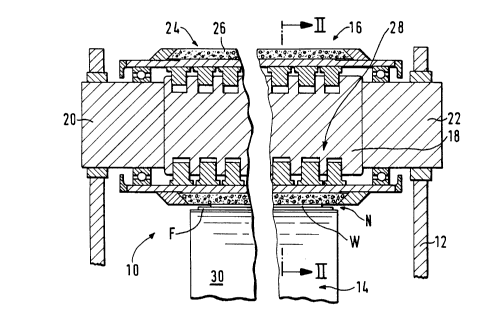
Figure 1 is a fragmentary sectional view of a press
section apparatus defining a press nip according to the
present invention. The press section apparatus is generally
designated 10 ~nd the press nip N enables pressing of a web W
of paper. The apparatus 10 includes a frame 12 and a press
member generally designated 14 which is secured to the frame
12. A backing roll generally designated 16 is rotatably
secured to the frame 12. The backing roll 16 cooperates with
the press member 14 for defining therebetween the press nip
N.
MB084731328
~2333~
The backing roll 16 also includes a shaft 18 having a
first and a second end 20 and 22 respectively. The ends 20
and 22 of the shaft 18 are secured to the frame 12. A shell
generally designated 24 defines a granite outer surface 26.
The shell 24 is disposed substantially coaxially relative to
and around the shaft 18. The shell 24 is rotatable relative
to the shaft 18. A deflection compensating means generally
designated 28 compensates for relative deflection between the
shell 24 and the press member 14 during passage of the web W
through the press nip N.
In a more specific embodiment of the present invention,
as shown in Figures 1 and 2, the press section apparatus 10
includes a press member 14 which is a press roll 30.
It will be understood that the backing roll 16 shown in
Figures 1 and 2 is essentially a self-loading crown-
compensating roll in which the lower pistons exert a pressure
on the shell 24 in order to press the web W during passage
through the nip N. However, the upper pistons permit
separation of the backing roll 16 from the press roll 30 in
order to permit changing of a felt F shown in Figures 1 and
2.
In another embodiment of the present invention, as shown
in Figure 3, a press member 14A also includes a press shoe 32
and a movable blanket 34 which is disposed between the shoe
32 and the granite surface 26A such that the blanket 34 moves
with the web WA through the press nip NA.
MB084731328
~?23331
In one embodiment of the present invention, as shown in
Figure 3, the press shoe is a hydrodynamic shoe.
As shown in Figure 3, the press member 14A also includes
a housing 36 which defines a cylindrical cavity 38. The
cavity 38 is connected to a source of pressurized fluid 40.
Control means generally designated 42 controls a flow of the
pressurized fluid 44 to the cavity 38. The shoe 32 slides
relative to the cavity 38 such that when the control means 42
is in an operative first position thereof, as shown in Figure
3, the shoe 32 is urged towards the granite surface 26A for
pressing the web WA during passage of the web WA through the
press nip NA. When the control means 42 is in an inoperative
second position thereof, a flow of the pressurized fluid 44
to the cavity 38 is inhibited.
As shown in Figure 3, the backing roll 16A also includes
a first and second bearing 46 and 48 respectively disposed
between a shaft 18A and a shell 24A. The first and second
bearings 46 and 48 respectively are disposed adjacent to the
first and second ends 20A and 22A of the shaft 18A
respectively for rotatably supporting the shell 24A relative
to the shaft 18A.
In one embodiment of the present invention, as shown in
Figure 3, a granite sleeve 50 is disposed substantially
coaxially relative to the shaft 18A and around the shaft 18A.
The arrangement is such that when the web WA is pressed
MB084731328
2~3~3~
between the sleeve 50 and the press member 14A during passage
of the web WA through the press nip NA, deflection of the
sleeve 50 relative to the press member 14A is compensated
for.
As shown in Figure 3, a cylindrical metal support 52 is
disposed coaxially within the sleeve 50 for supporting the
sleeve 50.
In one embodiment of the present invention, as shown in
Figure 3, the shell 24A also includes a layer of resin binder
54 between the sleeve 50 and the support 52 for bonding the
granite sleeve 50 to the support 52.
In the embodiment of the present invention, as shown in
Figure 3, the shell 24A also includes a first and a second
end ring 56 and 58 respectively. The rings 56 and 58
threadably cooperate with the metal support 52 adjacent to
the first and the second ends 20A and 22A of the shaft 18A
respectively. The first and second end rings 56 and 58
define respectively a first and second tapered face 60 and 62
for cooperating with a first and second tapered ends 64 and
66 respectively defined by the granite sleeve 50 such that
when the rings 56 and 58 are threadably rotated towards each
other, the sleeve 50 is compressed and urged into close
conformity with the metal support 52.
In another embodiment of the present invention, as shown
in ~igure 4, the press shoe is a hydrostatic shoe 32B
-14-
MB084731328
_ ~2333~
defining a plurality of hydrostatic bearing pockets for
urging the blanket 34B towards the shell 24B.
In another embodiment of the present invention, as shown
in Figure 5, the backing roll 16C also includes a first and
second end plate 68 and 70. Figure 6 is a sectional view
taken on the line 6-6 of Figure 5 and shows the plates 68 and
70 defining a first and second plurality of circumferential
holes generally designated 72 and 74 which extend axially
through the plates 68 and 70 respectively. Also, a plurality
of tie rods 76,77,78,79,80,81,82,83,84,85,86,87,88,89,90,91
extend through the holes 72 and 74 as shown in Figure 6. The
rods 76-91 also extend through a further plurality of axial
holes generally designated 92 and 94 extending axially
through the shell 24C as shown in Figure 5. The arrangement
is such that the first and second plurality of holes 72 and
74 and the further plurality of holes 92 and 94 are aligned
so that when the tie rods 76-91 are tightened, the end plates
68 and 70 support and compress the shell 24C which is of
granite.
The deflection compensating means 28C, as shown in
Figure 5, also includes a plurality of pistons 96,97,98,99,
100,101,102,103,104,105,106,107 which are disposed between
the shaft 18C and the shell 24C in the vicinity of the press
nip NC. The shaft 18C defines a plurality of bores 108,109,
110,111,112,113,114,115,116,117,118,119 for the slidable
reception therein of the piston 96-107. The bores 108-119
are connected to a source of pressurized fluid.
MB084731328
2~23331
Control means 120 controls the current of pressurized
fluid into the bores 114-119 such that when the control means
120 is disposed in a first operative position thereof the
fluid flows selectively into the bores 114-119 for urging the
pistons 102-107 along the bores 114-119 towards the press
member 14C for compensating for deflection between the shell
24C and the press member 14C.
When the control means 120 is disposed in a second
inoperative position thereof, the current of fluid to the
bores 114-119 is cut off.
The control means 120 also enables a further current of
fluid to bores 108-113 for urging pistons 96-101 upwardly to
separate the crown compensating or backing roll 16C from
press roll 14C.
In the embodiment of the present invention, as shown in
figure 3, the deflection compensating means 28A also includes
the control means 42 for controlling the current of
pressurized fiuid such that when the control means 42 is
disposed in the first position thereof, the shoe 32 and the
pistons 102A-107A respectively are urged towards each other
and an equal pressure is applied within the cavity 38 and the
bores 114A-119A so that deflection between the shell 24A and
the press member 14A is compensated for. When the control
means 42 is disposed in the second position thereof, pressure
within both the cavity 38 and the bores is simultaneously
-16-
MB084731328
~0~331
rel~ased for inhibiting any radial stress between the press
member 14A and the shell 24A.
In operation of the apparatus according to the present
invention, hydraulic pressure is applied within the bores
114A-119A for compensating for pressure applied by the shoe
32 so that deflection of the granite sleeve is compensated
for.
However, in the event of a sudden pressure loss within
the deflection compensating means, the arrangement is such
that the pressure within the press member would be
simultaneously released thereby inhibiting radial stress
being applied to the granite sleeve which could otherwise
result in damage or fracture thereto.
In each of the foregoing embodiments, the backing roll
is essentially a self-loading crown-compensating roll and the
pistons therein may be linear pistons slidably disposed
within corresponding rectangular-shaped grooves. Each piston
has a plurality of segments in order to selectively apply
pressure to the shell and for controlling the pressure
applied along the cross-machine direction. The lower pistons
are used to provide the necessary pressure in the pressing
nip in the case of use of a plain press roll and for applying
both pressure and compensating means when the press roll is
replaced by an extended nip press.
The upper pistons assist in separating the crown-
MB084731328
2~33~ 1
compensating roll upwardly away from the press roll orextended nip press permitting changing of the felt or felts.
The present invention provides a simple and inexpensive
arrangement for providing a granite press roll with
deflection compensating means.
-18-