Note: Descriptions are shown in the official language in which they were submitted.
` - 2 ~ 3 1
B~CKGROUND OF TilE INVENTION
The present invention is directed to a method for the
surgical correction o~ female urinary stress incontinence and a
kit thereEor. More particularly, the present invention is
directed to a surgical technique for ueethropexy and a kit
containing materials to eEfectuate the technique.
Female urinary stxess incontinence is treated
surgically by tying the urethro-vesical junction to the back of
the symphysis pubis. Kelly 1913, Marshall 1949, Pereira 1949,
l Burch 1961, Stamay 1973, Mason 1975, Cobb et al. 1978 and Eereira
¦ et al. 1978 have all helped to refine the technique and to
improve the results. ~lowever, these prior techniques have
required the utilization oE general anesthesia and have not been
conducive to repeat performances, even though such re-operation
may be dictated in numerous cases.
It is an object of the invention to provide a surgical
technique for urethropexy which may be performed under local
anesthesia.
It is a further object oE the invention to provide a
surgical technique for urethropexy which is generally applicable
to patients in need thereof, allows for repe~cition thereof, i~
necessary, while reducing morbidity and cost.
It is a still further object of the invention to
provide a kit containing devices necessary to effectuate the
surgical technique.
It is a yet further object to provide a device to
effect said urethropexy, when necessary.
- 20~3~31
These and other objects of the invention, as will
become apparent hereinafter, have been attained by the provision
of a method for surgically correctlng female urinary stress .
incontinence comprising the steps of:
(1) proviaing a pair of implants, each of said
implants comprising a head portion and 5 suture portion, said
head portion adapted to rest on the symphysis pubis, said suture
portion comprising a surgical suture acceptable, substantially
non-biodegradable thread connected to said head portion, said
thread having`a first end and a second end disposed on a single
side of said head portion;
(2) providing at least one needle, said at least one
needle comprisin~ a cannula and a trocar, said cannula being
receivable of said trocar, said trocar being removably disposable
within said cannula, said at least one needle being bendable to a
desired degree of curvature, said first and second ends of said
thread being guidingly receivable within said cannula;
(3) incising only the vaginal mucosa with an incision
about 1 cm in length at the urethro-vesical junction;
(4) introducing said needle at the right distal
extremity oE said vaginal incision and non-traumatizingly guiding
said needle along the symphysis pubis to a first point about 3 cm
to the right of a median line at the superior border of the
symphysis pubis and passing said needle through the skin at this
first point
(5) incising the skin with a cutaneous incision about
O.S cm in length at said first point
(6) removing said trocar from said needle while
leaving the cannula in place~
'- 2023~31
(7) introducing the first end of said thread from one
of said pair of implants into said cannula until it protrudes
into the vagina;
(8) withdrawing said cannula through the vagina
~9) introducing said needle at the right distal
extremity of said vaginal incision and non-traumatizingly guiding
said needle along the symphysis pubis to saia incision of step
(O;
(10) removing said trocar from said needle while
leaving the cannula in place;
(11) introducing th~ second end of said thread from
said one of said pair of implants into said cannula until it
protrudes into the vagina;
(12) withdrawing said cannula through the vagina;
(13) introducing said needle at the left distal
extremity oE said vaginal incision and non-traumatizingly guiding
said needle along the symphysis pubis to a second point about 3
cm to the left of a median line at the superior border of the
symphysis pubis and passing said needle ~hrough the skin at this
second point;
~14) incising the skin with a cutaneous incision about
0.5 cm in length at said second point;
(15~ removing said trocar from said needle while
leaving the cannula in place;
(16) introducing the first end of said thread from the
other of said pair of implants into said cannula until it
protrudes into the vagina
(17) withdrawing said cannula through the vagina;
(18) introducing said needle at the left distal
extremity of sald vaginal inclsion and non-traumati~ingly guiding
~ 20~3~31
said needle along the symphysis pubis to sald incision of step
(14);
(19) removing said trocar from said needle while
leaYing the canula in place;
(20) introducing the second end of said thread from
the other oE sald pair o implants into said cannula until it
proteudes into the vagina;
(21) withdrawing said cannula through the vagina;
(22) burying each of said implants under the skin over
1~ the symphysis pubis;
(23~ adjusting the urethro-vesical angle to a desired
¦position;
l (2~) tying the ends of said threads from the right
¦side to respective ends of said threads ~rom the left side to
¦hold the desired urethro-vesical angle.
¦ Additionally, the present invention provides a kit for
¦ use in the surgical correction of female urinary stress
¦incontinence comprising:
¦ at least one needle, said needle comprising a cannula
¦ and a trocar, said cannula being receivable of said trocar, said
¦ trocar being removably disposable within said cannula, said
needle being bendahle to a desired degree of curvature; and
a pair of implants, each of said implants comprising a
head portion and a suture portion, said head portion adapted to
rest on the pubic bone, said suture portion comprising a surgical
suture acceptable, substantially non-biodegradable thread
connected to said head portion; said thread having a first end
and a second end disposed on a single side of said head portion,
said first and second ends being guidingly receivable within said
cannula.
~ 2023~3~
In a particularly preferred embodlment, the kit
comprises:
a pair of implants, each of said implants comprising a
head portion and a suture poxtion, said head portion comprising a
substantially figure eight shaped member having a central cross
bar, said suture portion comprising a surgical suture acceptable,
substantially non-biodegradable thread having a first end, a
second end and a central portion, said central portion being
wrapped about said central cross bar with said first and second
ends disposed on a single side oE sald figure eight shaped
member;
a pair of needles, each of said needles comprising a
cannula and a trocar, said cannula being receivable of said
trocar, said trocar being removably disposable within said
cannula, each of said needles being bendable to a desired degree
of curvature, said cannular in use, being guidingly receivable of
said first end and said second end of said thread;
a tray for supporting and packaging said pair of
needles and said pair of implants.
~0 The present invention also provides a saddle for
supporting a neck portion of the female urethra comprising:
a substantially rectangular, planar base, said base
having an upper surface, a lower surface and four corners;
a pair of arms protruding upwardly and outwardly from a
central portion of said upper surface of said base, said arms
being integrally formed with said base and forming a
substantially V-shaped notch therewith;
a reinforcing element attached to said lower surface of
said base and substantially coextensive therewith;
. 20~3~31
means defining an aperture in each o the four corners
of said base, each said aperture passing through said base and
said reinforcing element.
Fig. lA is a front view oE a surgical lmplant,
accordinq to the present invention, useful in the surgical
procedure of the present invention.
Fig. lB is a side view of the surgical implant
illustrated in Fig. 1~. ~
Fig. lC is a top view of the ~urgical implant
illustrated in Fig. lA.
Fig. 2 is a plan view of a kit according to the present
invention.
Fig. 3~ is a front view of a saddle, according to the
present invention, useful in the surgical procedure of the
present invention.
Fig. 3B iR a ~ide view of the saddle ~llustrated in
Fig. 3A.
Fig. 3C is a top view of the saddle illustrated in Fig.
3~.
The present invention provides a surgical corrective
technique for all human female stress urinary incontinence
including fibrous perineal tissue due to irradiation by surgery
or trauma. In particular, the technique is particularly suitable
for patients suffering from coronary artery disability and
chronic obstructive pulmonary illness, as well as elderly
patients and patients suffering from Alzheimer's disease, etc.
The only contra-indication is for patients whose vaginal tissue
` ~ - 2~23~31
cannot support abdominal pressure. ~ladder atony, in itself, is
a contra-indication.
A proper diagnosis depends upon a pertinent
questionnaire stipulating the frequency and the quantity of
urinary incontinence. Conscientious study of the matter
concerning bladder instability is also required.
A proper diagnosis also depend~ upon an adequate
physical examination. In particular, after a complete
micturition in the lithotomy position, the examination must
reveal the degree of cysto-urethrocele as well as the mobility of
the perineal and urethral tissue structures. Then, a cystoscope
is introduced into the urethra, and residual urlne is recorded
and the bladder is then slowly distended, without pressure, while
the urethra and bladder are visually inspected. The length of
the urethra is recorded at the start of the inspection and when
the bladder is full, but not diætended. The cystoscope is
removed and the patient is asked to cough several times. Stress
incontinence is clearly noted when urine exits the urethral
meatus simultaneously with the coughing. A delay of a few
seconds in the incontinence indicates a hyporeflexic or unstable
bladder. Finally, the Bonney Test (Marshall) is performed to
confirm the continence and to indicate the necessary degree of
urethropexy.
Upon a diagnosis dictating surgical lntervention, the
following technique is utilized.
Preparation
A urine culture is taken and, if the urine culture ls
negative, no antibiotics are necessary. A pre-operative
¦medication, e.g., Diazepam ~5 gm) is administered to alleviate
`- '~ 2~2~3~
¦anxiety, with the patlent in the lithotomy position, knees
¦slightly withdrawn.
¦ Local Anesthesia
A catheter, e.g., a ~o. 18 Foley catheter, is placed to
empty the bladder. Tl-en, a local anesthetic, e.g., 4 cc of
Xylocaine 2~, is injected about 3 cm to the left and about 3 cm
to the right of the median line, precisely at the superior border
of the symphysis pubis up to about 4-5 cm in depth. ~.fterwards,
a small retractor allows visualization of the urethro-vesical
junction region in the vagina, and a local anesthetic, e.g.,
about 2 cc of Xylocaine 2~, is injected at this point.
Intervention
_
~s will become apparent herelnafter, the intervention
comprises the placement of two implants which will anchor sutures
holding the urethro-vesical juncture at a desired angle.
One of these implants is illustrated in Figs. lA, lB,
and lC. As may be readily ascertained, the implant, generally
indicated at 1, comprises a head portion 3 and a sut~re portion
5. The head portion 3 is adapted to rest on the pubic bone
(symphysis pubis) and is preferably of a substantially figure
eight configuration having a central cross bar 7, when viewed
from above. The head portion 3 may be formed of any medically
acceptable non-biodegradable implant material, preferably a
metallic material such as the surgical titanium alloy having the
ompositlon gl~ea 1~ Table 1.
2~3531
Table 1
Com~o ent ~ by wt.
Nitrogen 0.05
Carbon 0.08
llydrogen 0.012 Maxlmum
Iron 0.025
Oxygen 0.13
Aluminum 5.5-6.5
Vanadium 3.5_4.5
Titanium Balance
Such a titanium alloy has a tensile strength of about 130,000
psi and an elongation of about 120,000 psi. If desired, the head
portion 3 may be encased in a layer oE a biologlcally acceptable
coating material 9 (shown in phantom lines), e.g., medical grade
silicone rubber.
The suture portion 5 comprises a surgical suture
acceptable, ~ubstantially non-biodegradable thread having a first
end 11, a second end 13 and a central portion 15. The central
portion 15 is wrapped about the centraI cross bar 7 with the
2~ first end 11 and the second end 13 disposed on the same side of
the head portion 3. The thread used for the suture portion may
be any conventionally available, non-biodegradable suture
material, e.g., 0.5 mm diameter Surgilen (slue) or Prolene.
Typically, the first end 11 and the second end 13 will extend 25-
40 cms, preferably 30-35 cms, from the head portion 3.
The head portion 3~ typically, has a length (A) of
about 10-15 mm, preferably, about 12 mmt a width (C) o~ about 4-5
mm; and a height (s) of about 3-4 mm.
- ' 2a~3~3~
The intervention generally requires the utilization o
at least one needle, preferably a pair oE needles. The needles,
as illustrated in Fig. 2, each comprise a cannula 17 and a trocar
19. The trocar is removably, slidingly, disposable with the
cannula. Each oE the needles is bendable to a desired degree of
curvature. The needles are generally supplied with a radius of
curvature of about 100-105 mm, preferably about 102 mm, but may
be bent to conform to the internal curve of the patients vagina.
The needles are generally about lS0 mm long with the cannula
having an outside diameter of about 0.80 to 0.95 mm and with the
trocar having an outside diameter o about 0.60 mm, e.g., a l9.S
gauge needle.
The intervention generally proceeds, as follows:
~1~ incising only the vaginal muc~sa with an incision
about 1 cm in length at the urethro-vesical junction;
(2) introducing said needle at the right distal
extremity of said vaginal incision and non-traumatizingly guiding
said needle along the symphysis pubis to a first point about 3 cm
to the right of a median line at the superior border of the
symphysis pubis and passing said needle through the skin at this
first poil~t;
~3) incising the skin with a cutaneous incision about
0.5 cm in length at said first point
(4) removing said trocar from said needle while
leaving the cannula in place
(5) introducing the first end of sald thread from one
of said pair of i~plants into said cannula until it protrudes
into the vagina,
(6) withdrawing said cannula through the vagina
`~ 2~23~31
(7) introducing said needle at the right dlstal
extremity of said vaginal incision and non-traumatizingly guiding
said needle along the symphysis pubis to said incision of step
(5~;
~ 8~ removing said trocar from said needle while
leaving the cannula in place;
(g) introducing the second end of said thread from
said one of said pair of implants ir.to said cannula until it
protrudes into the vagina;
(10) withdrawing said eannula through the vagina;
(11~ introducing said needle at the left distal
extremity of said vaginal incision and r.on-traumatizingly guiding
said needle along the symphysis pubis to a second point about 3
em to the left of a median line at the superior border of the
symphysis pubis and passing said needle through the skin at this
seeond point
(12) incising the skin with a eutaneous ineision about
0.5 cm in length at said second point;
(13) removing said troear from said needle while
leaving the cannula in plaee
(14) introducing the first end oE said thread from the
other of said pair of implants into said eannula until it
protrudes into the vagina
(lS) withdrawing said eannula through the vagina;
~16) introducing said needle at the left distal
extremity of said vaginal lneision and non-traumatizingly guiding
said needle along the symphysis pubis to said ineision of step
(14)
(17) removing said trocar from said needle while
leaving the eanula in plaee
- 2 ~ 3 ~
(18) introduclng the second end of said thread from
the other of sald pair of implants into ~aid cannula until it
protrudes into the vagina;
(19) withdrawing said cannula through the vagina
(20) burying each of said implants under the skin over
the sympllysis pubis;
~ 21) adjusting the urethro-ve~cal angle t~ a desired
position;
(22) tying the ends of said threads ~rom the right
side to respective ends of said threads from the left side to
hold the desired urethro-vesical angle.
If desired, the ends of the respective threads may be
threaded through a rein~orcing element to provide additional
support. Such a reinforcement may be as simple as a small strip
of biologically acceptable cloth, e.g., medical grade Dacron
(polyethylene terephthalate polyester~.
~lowever, in the case of a reoccurrence of incontinence
after a first procedure, as noted above, a saddle as illustrated
in Figs. 3A, 3B and 3C may be used to hold the neck o the
urethra, following its contour, while provlding increased
rigidity. The saddle, generally indicated at 21, comprises a
substantially rectangular, planar base 23 having an upper surface
25, a lower surface 27 and four corners. A pair of arms 37, 39
protrude upwardly and outwardly from a central portion 41 of the
upper surEace 25 of the base 23. The arms are lntegrally formed
with the base, from medical grade silicone rubber, and form a
substantially V-shaped notch (best seen in Fig. 3s) to support
the neck portion of the urethra proximate the urethro-vesical
junction. A reinforcing element 43 is attached to the lower
3~ surface 27 oE the base 23 and extends coextensively with the base
~ 2023~3~
23. ~ series of bores 45, 47, 49, 51, havlng a diameter of about
0.7 mm, are provided in respectiye corners 29, 31, 33, 35 of the
saddle 21 so as to receive the various ends oE the threads from
the implants therethrough. The ends of the threads may be tied
together to support the saddle, which in turn supports the neck
portion of the urethra at a desired angle. The reinforcing
element 43, which may be formed of medical grade polyester, e.g.,
Dacron (polyethylene terephthalate), prevents the threads from
cutting the silicone rubber forming the base 23. The saddle 21,
typically, has a length (D) of about 15 mm, although it may be
supplied in different lengths so as to better conform to normally
expected physiological dif~erences between patients, e.g.,
lengths of 18.5 mm and 22 mm could also be supplied; a width (F)
oE about 20 mm; and a height (E) of about 10 mm. The reinforcing
element 43 has a height (G) of about 1 mm.
Veri~ication
Prior to the above-noted steps ~20), (21) and (22), the
Foley catheter is removed and a cystoscope is introduced to
ensure that suture material is not present in the bladder, and,
if necessary, to ensure that the bladder neck is not closed by
traction on the implants. The bladder is left full and the
instrument removed. Then, as noted above in the Intervention
section, the implants may be buried under the skin, using
hemostatic forceps, over the symphysis publs while making sure
not to create an umbilicus. By asking the patient to cough, to
demonstrate incontinence, the sutures are then tied by lifting
the urethro-vesical junction to a desired angular position.
Again, the patient is asked to cough and continence is
immediately ob~erved. The sutures, parallel to one another, are
` now tied up at the same position.
- ` 2~23~3~
Tl~e patient is then asked to try and void. This is
senerally impossible. ~ cystostomy is then performed or a Foley
catheter is intoduced. This concludes the procedure.
Post-O~eration
The patient can be mobile, drink and eat right after
her operation. An analgesic may be needed for several hours
post-operatively. ~ntibiotic therapy is not indicated unless the
urine culture was positive. Normal voiding may start as early as
the next morning, after the cystostomy is closed or the catheter
removed. In ~5% of the cases the cystostomy is closed or the
catheter removed on the third day ~although in some cases it has
been as long as 22 days). Patients are examined at 3 days, 2
months, 6 months and 1 year after the procedure.
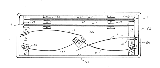
As previously noted, the present invention also
provides a kit, illustrated in Fig. 2 to aid in effectuation of
the surgical procedure disclosed above. The kit provides a pair
of needles comprising two cannula 17 and two trocars 19 and a
pair of implants 1. The needles and implants are packaged on a
tray 53 comprising a planar central portion 55 surrounded by an
~0 upstanding circumferential wall 57 and a lip 59 extending
outwardly from the top of the wall 57. A plurality of raised
portions 51 are formed on central portion 5S and define a
plurality of gaps 63 therebetween. A pair of hollow cylinders 65
supportingly receive respective suture portions 5 of the pair of
implants 1 therein. These hollow cylinders 65 and portions o~
said trocars 19 and cannulae 17 are engagingly received within
the gaps 63 so as to hold the implants, trocars and cannulae in
predetermined positions on the tray 53. The tray may be formed
¦ of any substantially rigid material capable of withstanding
¦ conventional sterilization techniques without ~allure, e.g., a
~ 2~23~31
.- . ,
thermoset re~in. A cover (not shown), such as a clear film, may
be bonded to the lip 59 of the tray, or preferably the tray may
be packaged in a wrapping, to allow sterilizatlon of the tray and
its contents.
The above-described surgical peocedure has been tested
on 145 patients. ~ break-down of the patients by prior history
and age is given in Table 2. The overall results for the group
o patients are set forth in Table 3. The results, by prior
l~istory grouping, are set forth in Table 4. The résults, by age
grouping, are set forth in Table 5. The explanation of those
patients experiencing recurring incontinence are set forth in
Table 6. The complications noted in the procedure are set forth
in Table 7.
Table 2 - GROUPS
Prior i~istory
A) First Surgery 74 women
s) Recurring Incontinence65 women
11 to 3 prior surgical procedures)
C~ More than 3 prior surgical procedures 6 women
~ccording to Age
1) More than 75 years old12 patients
2) From 65 to 75 years old52 patients
3) From 30 to 65 years old72 patients
4) Below 30 years old9 patients
Table 3 - OVERALL RESULTS
TOTAL PARTIAL CONTINENCE __
TOTAL PATIENTS CONTINENCE (COMFORTABLE) SUCCESS FAILURE
. ... ~ .. ___
Follow-up 91~ (133) 3~ ~5) 95~ (138) 5~ (7)
6 mths 145
I~_y~ wg u, ~ ~ 7
"- 2~3~3~
Table 4 - RESULTS BY PRIOR ~IISTORY
TOTAL PARTIAL CONTINENCE .
PATIENTS CONTINENCE (COMFORTABLE) SUCCESS FAILURE
_
... _ ... _. .. _
GROUP A-_ lST SURGICAL PROCEDURE _
6 mths 74 90% (70/74) 2~ (2/74) 97% (72/74) 23 (2/74)
1 yr 48 90%_(43~48) 6% (3/48) . 96% (46/48) 4~ (2/48)
GROUP B: FROM 1 TO 3 PRIOR SURGICAL PROC EDURES
.. .....
6 mths 65 90% (59/65) 3~ (2/63) 193% (61/65) 6~ (4/65)
1 yr 38 90~ (34/38) 2~ (1/38) ¦96~ (35/38) 7.5~ (3/38)
GROUP C: MORE T~IAN 3 PRIOR SURGICAL PROC EDU~ES
6 mths 61 66~ (4/6) ¦ 0~ 66~ (4/6) 33% (2/6)
1 yr 6l 66~ (4/6) 1 0~ 66% (4/6) 33~ (2/6)
Table 5 - ~ULIS AOCORDING TO AGE
TCrrAL PAl~IAL CONI INENCE _
CONTINENCE _ (Co~RTABLE) SUCC~S ¦ F~ILURE
.
>75 years 6 mths 12 83% 10/12 0~ 0/12 83~ 10/12 17% 2/12
1 yr 7 71~ 5/7 15% V7 85% 6/7 15% ~7
From 65 to 6 mths 52 94% 49/52 2~ 1/52 96~ 50/52 4~ 2/52
75 1 vr 33 91~ 30/33 3~ 1/33 94~ 31/33 6~ 2/33
~0From 30 to 6 mths 72 93~ 67/72 4~ 3/72 97~ 70/72 3~ 2/72
65 1 yr 45 B8~ 40/45 6~ 3/45 94% 43/45 4~ 2/45
<30 years 6 mths 9 77% 7/9 11% 1/9 88% 8/9 11~ ~9
1 yr 7 70% 5/7 15~ ~7 85% 6/7 15~ ~7
Table 6 - RECURRING INCONTINENCE
7 patients showed recurring incontinence:
- Two (2) patients had a neurogenic bladder and 1 of
those two (2) was re-operated without success.
- In two (2) pat~ents the surgery was considered
incomplete and we simply placed two implants in a
more proximal location.
- In three (3) patients the slings (sutures) migrated
in the vagina; the implants were replaced and Dacron
was Insert~d in the f ndus oE the vagina.
- ~ 2023~31
Table 7 - COMPLICATIONS
Major
- ~ retroperitoneal hematoma (Factor VIII)
drained 21 days later.
Minor
- Infection, following implants 6/290
- Expulsion of implants through skin 2/290
- Excessive Pain (implant removed) 1/145
- Intravesical slings ~suturesn 3/290
(prior to cystoscopy)
- Inflammatory reaction > 10 days6/145
- Pain 2/145
- Urinary retention more than 3 days 21/145
more than 6 days 6/145
The above described transfixation technique is totally
unique in that it uses implants on the symphysis pubis and in
that it is performed under only local anesthesia, as compared to
existing procedures. It requires only a short llospital stay and
it is equally applicable to the young and athletically inclined
person and the high-risk surgical patient. If necessary, it is
190 a repeatable te~hnlque.
17