Note: Descriptions are shown in the official language in which they were submitted.
~2~
BACRGROUND OF l'HE INVENTION
The invention relates to a robotic camera dolly system,
and more specifically to such a system which can remotely and
automatically direct a camera dolly among studio floor
positions.
As the television broadcast market continues to mature,
there is growing interes~ in controlling costs and improving
equipment utilization through the greater use of automation.
Newsrooms are leading the way. Central computers are being
used to organize the overall news gathering process and the
sequencing of the show, and increasingly to control certain
studio equipment such as teleprompters.
The trend is toward controlling ever more studio
equipment, such as lighting, character-generators, and
effects generators.
Cameras, however, are still manually controlled despite
the fact most of their shots are well structured, highly
repetitive, and known in advance. Automating them therefore
has the potential to further reduce costs and improve
equipment utilization in an automated studio. Automating
shot taking would require that the shots be framed before the
television show, assigned names, and then recalled as needed.
A camera shot can be thought of as consisting of seven
parameters, all set by the cameraman. They are camera focus,
. .
.
.
~3~
zoom, tilt, pan, pedestal height, and the x and y positions
of the camera dolly on the floor. Ideally all seven degrees
of freedom are servo controlled, and stored as a set. The
control and storage of the first four parameters: focus,
zoom, tilt, and pan, is known within the prior art. Examples
are the products manufactured by Total Spectrum Manufacturing
Inc., known as the Multicontroller and the HS-110-P robotic
camera head. Partial camera automation is practical at this
level, but the cameras must either be anchored, or dollied
about manually. These restrictions tend to nullify the gains
of automation, obtainable with respect to focus, zoom, tilt,
and pan, since the restrictions require manual intervention,
or additional cameras, or aesthetic compromises.
One way to achieve mobility $s to place the cameras on a
track; however this method has its drawbacks. It clutters
the floor, is expensive to relocate, is one-dimensional,
limits camera locations to those along the track, and
prevents the cameras from crossing past each other.
Another way to achieve mobility is to place the cameras
on wheeled dollies and, with the aid of a motor control
system, to direct the dollies to the appropriate camera loca-
tions and angular orientations. However, thi~ approach runs
into the problem of assuring precision in movements which may
be of the order o~ 50 feet in a typical television ~tudio, it
- 3 -
,
,
;
2~2~
being obviously very important in television production thatboth the location and orientation of the cameras be properly
located while shooting. Moreover, when a series of predeter-
mined locations is to be traversed by the camera the problem
would become successively magnified as such errors would
accumulate from shooting location to shooting location.
SUMMARY OF THE INVENTION
An object of the invention is, therefore, to provide a
dolly apparatus which can be taught to automatically trans-
port a video camera between preselected locations and angularorientations with great precision on a studio floor.
In accordance with one aspect of the invention this
object is met with a dolly apparatus which can be taught to
automatically transport the camera under open loop control
(dead reckoning) to the immediate vicinity of targets
positioned at and/or in relation to preselected locations on
the studio floor, and with the aid of sensors on the dolly,
to thereafter correct the translational position and the
angular orientation of the dolly and/or the camera with
respect to the targets.
In accordance with another aspect of the invention, the
dolly carries a camera carriage which can raise and lower and
rotate the camera in a conventional manner, and rides on
- 4 -
-: .
:
2 ~
powered and 6teerable wheels which are controlled first in an
open loop manner and then in a closed loop manner with target
sensors in order to bring the dolly close to, and then
precisely on, a target.
In accordance with another aspect of the invention, the
targets are marked in the plane of movement of the dolly,
such as on a studio floor, and designate at least two
translational positions from which camera shots are to be
taken. The targets may also mark the angular orientation
which the dolly should adopt at the respective translational
positions. Sensor~means such as a plurality of downwardly
directed optical sensors are provided on the dolly for
detecting the translational position and angular orientation
of the dolly relative to the target when the dolly has
reached the close vicinity of the target by dead reckoning.
A computer-based dolly controller is connected to the
dolly via a serial data link. The controller contains a
control stick, coupled to the wheels via the serial data link
and used to control steering and propulsion of the wheels,
and is employed to teach the motions to be performed during
the dead reckoning movement. The computer contains means to
continually sample and store for future use, the instan-
taneous position demand signals which instruct the speed and
steering of the wheels. This teaching approach is analogous
...... :
2~2~
to the manner in which the aforementioned Multicontroller and
HS-llO-P robotic head can be used to teach and store coor-
dinated pan, tilt, zoom and focus motions of the robotic head
and the camera which it supports. In the case of teaching
speed and steering of the dolly wheels, the taught motion may
be somewhat complicated to move from one camera location to a
second one, for example from a weather set to a news set, the
path and speed being chosen by the computer operator so as to
avoid other cameras and other obstacles, and being stored in
the computer.
In accordanc,e with one other embodiment of the inven-
tion, the movement of the dolly from one target to the next
is taught in steps, that is, along a succession of selected
points along the floor.
During such movements, the wheels normally all point in
the same direction: in television terms, the wheels move in
a "crab mode". When the dolly has reached the immedlate
vicinity of the target in completing the first stage of
repositioning the camera to a new camera shooting position,
the wheels move in the crab mode to correct the translational
position and may be steered to be tangent to a circle to
allow the dolly to rotate for correcting the angular orienta-
tion.
- 6 -
2~23~ ~
With a target of about two feet square photoreproduced
on the floor and having sufficient detail to allow automatic
centering of the dolly above it, as well as to correct its
angular orientation, it i~ necessary only that the dead
reckoning control be capable of guiding the dolly to within a
foot or so of its desired location, from which the alignment
control will be able to sense the target in order to perform
the automatic centering and correction of angular orienta-
tion. The intrinsic accuracy of the dolly and the dead
lo reckoning control is such that the dolly is capable of
traversing typical,studio distances of 50 feet ending up
within a foot of the destination target with only a æmall
error in angular orientation, so as to be within homing range
of the destination target.
The targets do not have to be aligned in either position
or rotation to any absolute grid or coordinate system. Since
the 6ystem is taught a path and speed between particular end
points, and traces this track by dead reckoning, the only
reference required i8 the actual positlon and orientation of
the target from which the dolly ~tarts its move (and which
therefore defines the starting position and orientation of
the dolly). In effect, the person teaching the motion shows
the dolly system the coordinates of the destination target,
using the reference from the origin target. Subsequent moves
:4 -
'
2023~19
begin anew, and each move has context only with respect to the
target from which it originates. It i5 this recalibrating
(the closed loop homing in o~ the target) at the end o~ each
move that allows repeated moving, from shooting location to
shooting location in a se~uence, to work. The system breaks
up a large problem into small manageable ones, allowing the
present camera automation system to work without accumulating
excessive errors.
In a first broad aspect, therefore, the present invention
relates to a posîtioning system for moving a dolly member
between first and second positions in a plane, said dolly
member having an axis of rotation normal to the plane and a
reference direction normal to said axis of rotation, said
dolly member further including first means for the translation
thereof in the plane and second means for the rotation thereof
about said axis of rotation, the system comprising: first and
second target means having fixed locations relative to the
fir6t and second positions on said plane respectively, each of
said target means having an origin defining its respective
position and re~erence means defining a given direction in the
plane; first control mean6 coupled to said fir6t means for
translating said dolly member, said ~irst control means
controlling the translation of said dolly member along a
predetermined path from said first position to a position at
which the axis of rotation of said dolly member is in the
vicinity of said second position: detecting means for
generating fir6t and second control aignals, said first
control signal corresponding to the noncoincidence of the axis
,~,
.'
.~ . - '. .
2023619
of rotation of said dolly member with the origin of said
second target means and said second control signal
corresponding to the noncoincidence of the reference direction
of said dolly member with the given directlon defined by said
second target means: and second control means coupled to said
first and second means for translating and rotating
respectively said dolly member, said second control means
being responsive to said first and second control signals for
controlling the translation of said dolly member to bring the
lo axis of rotation thereof into coincidence with the origin of
said second target means and controlling the rotation of said
dolly member to bring the reference direction thereof into
coincidence with the given direction defined by said second
target means.
In a second broad aspect, the present invention relates
to a robotic dolly system for moving dolly member between
first and second spaced apart positions in a plane, the dolly
member having an axis of rotation normal to the plane and a
reference direction normal to the axis, the first position
being defined by coincidence of the axis with a first point in
.the plane and coincidence of the reference direction with a
irst given direction in the plane, the second position being
defined by coincidence of the axis with a second point in the
plane and coincidence of the reference direction with a 6econd
given direction in the plane, the 6ystem further comprising: a
target means for defining the first and second points in the
plane and for defining the first and second given direction6
- 8(a) -
:
,
2023619
in the plane; means for translating said dolly member in the
plane; means for rotating said dolly member about the axi~;
first control means for controlling ~aid tran~lating ~eans to
translate said dolly member along a predetermined path from
the first position to an intermediate position in the plane at
which the dolly axis intersects an intermediate point in the
plane in the vicinity of the second point and at which the
reference direction is at an intermediate angle to the second
given direction; means for detecting said target means, and
for producing in response to at least one of detection and the
absence of detection, of said target means, detection signals
indicative of at least one of coincidence and noncoincidence
of the axis and the second given point and the existence of at
least one of a nonzero angle and a zero angle between the
reference direction and the second given direction; and second
control means, responsive to the detection signals, for
controlling said translating means and said rotating means to
rotate and translate said dolly member to bring the axis and
the second given point into sub~tantial coincidence and reduce
substantially to zero the angle between the reference
direction and the second given direction.
In a third broad aspect, the present invention relates to
a method of moving a robotic dolly member between a first
position in a plane and a second position in the plane, the
dolly member having an axis of rotation normal to the plane
and a reference direction normal to the said axis of rotation,
tha dolly member further including first means for tran~lation
- 8tb) -
2023619
thereof in the plane and second means for rotation thereof
about said axis of rotation, the method compri~ing the steps
of: locating first and second targets having origins in
respectively fixed relation to and respectively defining the
first and second positions in the plane and respectively
defining corresponding first and second given direction6 in
the plane; providing the dolly member in the plane at the
first position with its axis normal to the plane and
intersecting the origin of the first target and with its
reference direction being the same as the first given
direction defined by the first target; teaching the dolly
member to respond to a start signal to move along a specified
path from the first position to the vicinity of the second
position whereat the axis of the dolly member is in the
vicinity of the origin of the second target; producing the
start signal to initiate translation of the dolly member in
the plane along the taught specified path from the first
position to the vicinity of the second position so that the
axis of the dolly member is in the vicinity of the origin of
the second target; detecting with sensing means on the dolly
member coincidenae and noncoincidence of the axis of the dolly
with the origin of the second target and the existenae of a
nonzero angle between the given direction defined by the
~econd target and the reference direction of the dolly member;
and durinq said 6tep of detecting, translating and rotating
the dolly member in the plane according to the coincidence and
noncoincidence of the axis of the dolly with the origin of the
- 8(c) -
; '
'
2023~19
second target and the existence of a nonzero angle between the
given direction defined by the second target and the reference
direction of the dolly member until the axis of the dolly is
6ubstantially coincident with the origin of the second target
and the angle between given direction defined by the ~econd
target is substantially zero.
In a fourth broad aspect, the present invention relates
to a positioning sy6tem for moving a dolly member along a
subætantially planar surface, said dolly member having a
lo rotation axis normal to said planar surface and a translation
axis parallel to said planar surface, said system comprising:
a target means for defining a reference point and a reference
direction on said planar surface; driving means for moving
said dolly member on said planar surface; detection means
affixed to said dolly member for detecting said target means;
and processor means coupling said detection means to said
driving means, said processor means controlling said driving
means to move said dolly member on said planar surface by dead
reckoning to a vicinity of said target means; and in response
to an output of said detecting means, controlling said driving
means to move said dolly member to bring the translation axis
thereof parallel to the referenoe direction defined by said
target mean~, and to bring the rotation axis o~ said dolly
member into coincidence with the reference point defined by
said target means.
In a fifth broad aæpect, the present invention relates to
a positioning system for moving a dolly member along a
- 8(d) -
''''``' :~
:
20236~9
substantially planar surface, said dolly member having a
rotation axis normal to said planar surface and a translation
axis parallel to said planar surface, said ~ystem comprising:
a target means for defining a reference point and a reference
S direction on said planar surface; driving means for moving
said dolly member on said planar surface: detection means
affixed to said dolly member for deteating said target means;
and a processor coupling said detection means to said driving
means, said processor including means for storing data
corresponding to a desired movement of said dolly member along
a predetermined path: controlling said driving means to move
said dolly member approximately along said predetermined path
on said planar surface by dead reckoning in accordance with
said stored data, the actual position of said dolly member
differing from said predetermined path by a position error
accumulated during movem~nt thereof, and then moving said
dolly member to the vicinity of said target means; and in
response to an output of said detecting means, controlling
said driving means to move said dolly member to bring the
translation axis thereof parallel to the reference direction
defined by said target means, and to bring the rotation axis
of said dolly member into aoincidence with the reference point
defined by said target means, whereby said dolly member is
positioned at sald reference point and said aacumulated
position error i8 eliminated.
In a sixth broad aspect, the present invention relates to
a positioning system for moving a dolly member along a
- 8(e) -
-" 2023619
substantially planar surface, said dolly member having a
rotation axis normal to the planar surface and a translation
axis parallel to the planar surface, said sy~tem comprising: a
target means for defining a reference point and a reference
direction on the planar surface; driving means for moving said
dolly member on the planar surface; detection means affixed to
said dolly member for detecting said target means; and
processor means coupling said detection means to said driving
means, said processor means in reæponse to an output of said
detecting means when said dolly member is in a vicinity of
said target means, controlling said driving means to move said
dolly member to a first position in which the translation axis
thereof is parallel to the reference direction defined by said
target means, and the rotation axis of said dolly member is
coincident with the reference point defined by said target
means, and controlling 6aid driving means to move said dolly
member on the planar surface by dead reckoning from said first
position to a 6econd position.
In a seventh broad aspect, the present invention relates
to a method of moving a dolly member along a substantially
planar surface, said dolly member having a rotation axis
normal to the planar surface and a translation axis parallel
to the planar surface, 6aid method comprising the steps of:
locating a target at a fixed position with respect to said
planar surface, said target defining a reference point and a
reference direction on said surface; moving 6aid dolly member
by dead reckoning from a position on the planar surface to the
. - 8(f) -
.,
.. , ~ , . . ., :
2023~19
vicinity of said target; and with the dolly member in a
vicinity of said target, detecting the target with detection
means affixed to the dolly member and outputting a detection
signal: and in response to the detection signal, moving the
dolly member to bring the translation axis thereof parallel to
the reference direction defined by the target, and to bring
the rotation axis of the dolly member into coincidence with
the reference point defined by the target.
In an eighth broad aspect, the pre ent invention relates
to a method of moving a dolly member along a substantially
planar surface, said dolly member having a rotation axis
normal to the planar surface and a translation axis parallel
to the planar surface, said method comprising the steps of:
locating a target at a fixed position with respect to said
planar surface, said target defining a reference point and a
reference direction on said surface; with the dolly member in
the vicinity of the target, detecting the target with
detection means a~fixed to the dolly member and outputting a
detection signal, and in response to the detection signal,
moving the dolly member to a first position on the planar
surface in which the translation axis thereof i8 parallel to
the reference direction defined by th~ target and the rotation
axis of the dolly member iB coincident with the reference
point defined by the target; and moving the dolly member by
dead reckoning from the first position on the planar surface
to a second position on said surface.
- 8(~) -
~.
- -
2023619
In a ninth broad aspect, the present invention relates to
a method of moving a dolly member along a substantially planar
surface, said dolly member having a rotation axis normal to
said planar surface and a translation axis parallel to said
planar surface, said method comprising the steps of: locating
a target means for defining a reference point and a reference
direction on said planar surface:storing data corresponding to
a desired movement of said dolly member along a predetermined
path; controlling a driving means to move said dolly me~ber
approximately along said predetermined path on said planar
surface by dead reckoning in accordance with said stored data,
the actual position of said dolly member differing from said
predetermined path by a position error accumulated during
movement thereof, and then moving said dolly member to the
vicinity of said target means; and in response to an output
from detecting means affixed to said dolly member for
detecting said target means, controlling said driving means to
move said dolly member to bring the translation axis thereof
parallel to the reference direction defined by said target
means, and to bring the rotation axis of said dolly member
into coincidence with the reference point derined by said
target means, whereby said dolly member is positioned at said
reference point and said accumulated position error is
eliminated.
.. 25 In a tenth broad aspect/ the present invention relates tothe method of controlling the movement of at least one camera
on a substantially planar floor having at least one target on
.
. - 8(h) -
. .
~ . ~
' ' , . ' ', , ` ::
~023~19
the surface thereof for defining a reference point and a
reference direction; said camera being mounted on a dolly
having a rotation axis substantially normal to said floor and
a translation axis substantially parallel to said floor: said
dolly being provided with motor means for the translation and
rotation thereof, and detection means for detecting said
target when said dolly is in the vicinity of said target, said
method comprising the steps of: (a) moving said dolly under
the control of a controller along a predetermined path from
said one target to another location on said floor, data
corresponding to ~aid predetermined path being stored in a
memory of a processor as said dolly traverses said pre-
determined path: (b) returning said dolly to the vicinity of
said one target under the control of said controller; (c)
controlling, in response to an output from said detection
means, said motor means to move the translation axis of said
dolly parallel to the reference direction defined by said one
target, and to bring the rotation axis of said dolly into
coincidence with the reference point defined by said one
target, whereby said dolly is positioned at said reference
point with a predetermined orientation; and (d) moving said
dolly along said deæired path from said one target in
accordance with the data stored in the memory of said
proceæsor, the movement of said dolly along ~aid path being
made by dead reckoning, the actual position of said dolly
differing from said predetermined path by a position error
accumulated during movement thereof.
- 8(i) -
:
.. . . .
2023~19
In an eleventh broad aspect, the present invention
relates to an apparatus for controlling the mDvement of at
least one camera along a predetermined path on a substantially
planar surface having at least one target thereon, said target
defining a reference point and a reference direction,
comprising a dolly supporting said camera, said dolly having
a rotation axis substantially normal to said surface and a
translation axis substantially parallel to said surface; motor
means affixed to said dolly, said motor means rotating said
dolly around its rotation axis and moving said dolly along
said surface;detection means affixed to said dolly for
detecting a target when the dolly is in the vicinity thereof;
a controller remote from said dolly for controlling the
movements thereof; and a processor coupling said controller to
said dolly, said processor having a memory and including means
for continuously storing data corresponding to the movement of
said dolly from a target along said predetermined path under
the control of said controller, there being no targets on said
predetermined path between the ends thereof; controlling said
motor means to repeat movement of said dolly along said
predetermined path by dead reckoning in accordance with $aid
stored data, the actual position of said dolly di~fering from
said predetermined path by a position error accumulated during
movement thereof: and controlling, in response to an output o~
said detection means when said dolly is in the vicinity of a
target, said motor means to move the translation axis of said
dolly parallel to the referenoe direction defined by said
- 8(j) -
. . ' ~
2023619
target, and to bring the rotation axis of said dolly into
coincidence with the reference point defined by said target,
whereby said dolly is positioned at said reference point with
a predetermined orientation.
In a twelfth broad aspect, the present invention relates
to apparatus in combination with a television studio having a
floor with at least one target marked thereon for defining a
reference point and a reference direction, and at least one
television camera movable on said floor along a predetermined
path, said apparatus comprising:a dolly supporting said
television camera, said dolly having a rotation axis
substantially normal to the floor of said television studio
and a translation axis substantially parallel to said floor;
motor means affixed to said dolly, said motor means rotating
said dolly around its rotation axis and moving said dolly
along said floor sur~ace; detection means affixed to said
dolly ~or detecting a target on said floor when the dolly is
in the vicinity thereof; a controller remote ~rom said dolly
for controlling the movements thereof; and a processor
coupling said controller to said dolly, said processor having
a memory and including means ~or continuously storing data
corresponding to the moVement o$ said dolly from a target
along said predetermined path under the control o~ said
controller, there being no targets on said predetermined path
between the ends thereo~; controlling said motor means to
repeat movement o~ said dolly along said predetermined path by
dead reckoning in accordance with said stored data, the actual
- 8(~) -
~`
,
:~'
.~
.:. . .
2023~19
position of said dolly differing from said predetermined path
by a position error accumulated during movement thereof; and
controlling, in response to an output o~ said detection means
when said dolly is in the vicinity of a target, said motor
means to move the translation axis of said dolly parallel to
the reference direction defined by said target, and to bring
the rotation axis of said dolly into coincidence with the
reference point defined by said target, whereby said dolly is
positioned at said reference point with a predetermined
orientation.
BRIEF DESC~IPTION OF THE D~WINGS
These and Otner aspects of the invention will be more
completely understood from the following description of the
preferred embodiment when taken with the accompanying drawings
in which:
Fig.lA is a perspective view of a robotic dolly with
photosensors for reading a "target", with the wheel assemblies
beinq omitted for simplicity of illustration;
Fig.lB is a schematic illustration of the electro-
mechanical elements of one of three identical wheel a6sembliesfor use with the dolly;
Fig.lC i8 a perspective view of the dolly with a camera,
head and support;
- 8(1) -
. . . .
.. . .
. . .
. , . ' '
~,
- ' , . ' ~ , ` -
2~&~ ~
Fig. 2 is a schematic illustration of a typical studio
floor, showing various positions to be taken by the camera
assemblies:
Fig. 3 is a block diagram of a television-camera dolly
system in accordance with a first embodiment of the present
invention:
Fig. 4A and 4B are flow charts of programs for the
teaching and repeat programs employed in the first embodi-
ment:
Figs. 5A-5F are schematic representations illustrating
the optosensors with respect to the target during alignment
in the first embodiment;
Fig. 6 is a flow chart illustrating the alignment
program for the first embodiment:
Fig. 7 is a block diagram of a studio system showing the
interconnection of various elements thereof and a newsroom
computer in a second embodiment of the invention: and
Fig. 8 is a block diagram of the electronics and motors
in the second embodiment.
DESCRIP~ OE TH~ D EMBODIMENT$
Referring now to Fig. lA, there i8 shown a camera
assembly 10 (with the wheel assemblies being omitted for ease
of illustration). The camera assembly 10 includes a dolly 12
:
: . '
. ,: '
2 ~2 ~
of generally equilateral triangle shape. At each of the
three corners of the generally equilateral triangle 6haped
bottom surface 14 of the dolly 12 are provided circular
openings 16 for shafts to mount the respective wheel
assemblies (not shown in Fig. lA). In a central portion of
the bottom surface 14 are provided optosensors 18 arranged in
a square pattern, with the diagonally opposite optosensors
18a and 18c being arranged on a line 18' parallel to the side
edge 14a of the bottom surface 14. The other diagonally
opposite optosensors 18b and 18d are arranged on a line
18 " which is perpendicular to line 18'.
The optosensors 18 are conventional devices which
project respective beams directly downward 60 as to focus
onto the studio floor, and which include respective sensors
to detect light reflected back from the floor. As will be
described in greater detail below, the optosensors are used
to precisely locate and orient the dolly with respect to one
of various targets 20 located on the studio floor. Targets
20 which is shown from below and, for the purpose of
illustration only, assumed to be partially transparent in
Fig. lA may, for example, be two feet square and consist of
adhesive-backed 6heets of acetate, with a pattern of two
black 6quares 22 and 24 and two white 6quares 26 and 28, the
boundaries between the squares defining X and Y axes. As
-- 10 --
; . , -
~. . ' " ' .
..
~ 3 ~
will be described in greater detail below, the optosensors 18
are utilized to detect the transitions between the black and
white squares. The optosensors 18 may, for example, be those
manufactured by TRW having part number TRW-OPB703A, and are
preferably spaced 1 foot apart when the target 20 i6 2 feet
square.
One of three identical wheel assemblies 30 is
illustrated in Fig. lB and includes a mounting shaft 32 for
mounting the wheel assembly in a respective opening 16 in the
lo bottom surface of the dolly 12. Wheel assembly 30 may be of
conventional design and may be a model number HS-105P
produced by Total Spectrum Manufacturing Company. Wheel
assembly 30 includes a casing 34 housing therein a 6teering
motor 36 which rotates the assembly 30 about the mounting
shaft 32 via anti-backlash reduction gears 38. A propulsion
motor 40 rotates the wheel 42 through an anti-backlash
reduction gears 43. Control of the respective motors for the
wheel assemblies will be described below.
Fig. lC illustrates the entire camera assembly 10.
Shown are the wheels 42 supporting the dolly 12 on which a
vertically ad~ustable pedestal 44 supports the horizontally
rotatable camera head 46. The camera head may, for example,
:: :
-` 2~236~9
be a conventional head such as the Total Spectrum Manu-
facturing model number HS-llOP. The camera 48 is therefore
rotatably and vertically adjustably mounted on the dolly 12
by the pedestal 44 and head 46.
In use, for example, on a television studio floor having
a news set, a weather set and a talk-show set, two or more
camera assemblies 10 may be employed and the pan, tilt, zoom,
focus and vertical height of the respective cameras con-
trolled via cables from a remotely located dolly controller.
Typical positions o$ the dolly and angular positions of the
cameras thereon are illustrated in Fig. 2 showing a typical
arrangement of a talk-show set, a news set and a weather set
with the camera assemblies lOa, lOb and lOc indicated in
front of the news set, alternate positions thereof in front
of the sets being shown in broken line. As can be seen in
Fig. 2, in order to move the camera assemblies 10 from one
location to the other without contacting the other camera
assemblies or otherwise interfering with their operation or
running over their respective cables 50, which extend from a
producer's booth 51, the camera assemblies 10 may be required
to take a somewhat complex or circuitous route. ~he cameras
need to be movable so as to allow at least two-camera
coverage of each of the two sets, a~ shown. On occasion, a
pull-back ~hot requires one of the cameras to recede from the
- 12 -
. ` '
.
.
.
~` 2 ~
set, during an on-air move. The various po6itions which the
dollies are to take are marked with targets as described
above.
~ camera assembly 10 moves from one target to another in
two steps. The first step moves the camera assembly 10 by
dead reckoning from one target to a position very close to
the other target (destination target) along a taught path.
Once the camera assembly has reached the vicinity of the
destination target, final alignment of the dolly is
accomplished in a closed loop manner with the aide of the
optosensors thereon sensing the target.
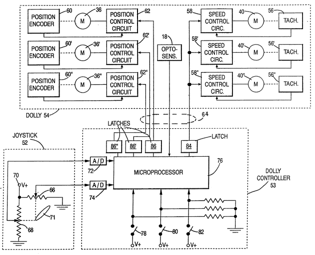
A simplified first embodiment of a robotic television-
camera dolly system in accordance with the present invention
will now ba described with reference to Figure 3, which
schematically illustrates a joystick 52, a dolly controller
53, and a dolly 54 having the same construction as the dolly
12 previously discussed with respect to Figures lA-lC. In
particular, dolly 54 includes optosensors 18 and three
wheels 42 (See Figure lC), one of which is rotated by the
propulsion motor 40 and directed (with respect to dolly 54)
by the steering motor 36. One of the remaining wheels is
rotated by propulsion motor 40' and directed by steering
motor 36', and the last wheel is rotated by propulsion motor
40 " and directed by steering motor 36 ". Motors 40-40" are
2 ~2 ~
mechanically connected to tachometers 56-56 ", which provide
feedback signals for speed control circuits 58-58 ". Speed
control circuits 58-58 " receive speed command signals from
dolly controller 53, as will be discussed. Position encoders
60-60", mounted on motors 36-36", are indirectly linked
thereto (although not illustrated in Figure lB) so as to
detect the relative positions of the casings 34 with respect
to the base of the dolly. Position encoders 19
60-60 " provide feedback signals for position control
circuits ~2-62 ", which additionally receive position or
steering command signals from dolly controller 53. Dolly 54
is connected to dolly controller 53 by a cable 64, which may
also include conductors (not illustrated) for various other
purposes such as providing power to the motors and returning
the video signal.
Joystick 52 includes an X-potentiometer 66 and a Y-
potentiometer 68. Each potentiometer is connected between a
power supply terminal 70 at a voltage V and ground. Poten-
tlometers 66 and 68 have sliding taps which are mechanically
connected to a ~oystick handle 71, this mechanical connection
being schematically indicated by the dotted lines in Figure
2. The mechanical connection is such that the sliding tap of
potentiometer 66 is moved in accordance with the X component
- 14 -
2~23~
of the movement of handle 71, and the sliding tap of poten-
tiometer 68 is moved in accordance with the Y component of
the movement of handle 71. Although not illustrated, handle
71 is preferably spring-biased, so that it returns to a
5 vertical position when it is released. In the vertical
position, the voltage at the tap of potentiometer 66 is V/2
and the voltage at the tap of potentiometer 68 is also V/2.
Dolly controller 53 includes an analog/digital converter
72 which is connected to the sliding tap of potentiometer 68
to receive the Y component of the signal from joystick 52,
and another analog/digital converter 74 which is connected to
the sliding tap of potentiometer 66 to receive the X com-
ponent. The resulting X and Y digital signals provide inputs
for microprocessor 76. Other inputs to microprocessor 76 are
provided by path-training switch 78, path-repeat switch 80,
and final alignment switch 82. Microprocessor 76 also
receives signals from optosensors 18. Based upon these input
signals microprocessor 76 generates a speed command signal
which is stored in speed control latch 84 to control the
speed of motors 40-40", and direction command slgnals which
are stored in direction control latches 86-86" to control
the directions in which motors 36-36 " aim their respective
wheels. Although not illustratQd in Figure 3, dolly con-
troller 53 may also include digital/analog converters
- 15 -
,
. ~:
2B23~
connected to latches 84 and 86-86 " to convert the command
signals to analog form before they are transmitted via cable
64 to dolly 54.
The path-training program will now be described with
reference to Figures 3 and 4A. It is assumed that dolly 54
is positioned over an initial target 20 (see Figure lA) and
is to be moved from this initial position to a final position
above a different target 20. An operator closes path-
training switch 78 and then manipulates the handle 71 of
lo joystick 52 to guide dolly 54 along the desired path. After
switch 78 has been,closed, a counter in microprocessor 76 is
reset at step 88. Thereafter, a timer 90 in microprocessor
76 is set. Timer 90 times-out after 1/15th second. At step
92, the X signal from A/D converter 74 and the Y signal from
A/D converter 72 are read at step 92. These signals need to
be corrected, since the X and Y signals both correspond to
V/2 when handle 71 is in its vertical position. This
correction is accomplished at step 94, where V/2 is sub-
tracted from each signal. The result is essentially a
transformation of coordinates, so that the movement of handle
71 can be interpreted thereafter in a true cartesian fashion;
that is, in the plus and minus X dlrections and the plu5 and
minus Y directions. The cartesian coordinates are then
converted to polar form at step 96. As a result, the
- 16 -
.
2~2~
cartesian coordinates of the position of handle 71 aretransformed into a radial signal and an angular signal. The
radial signal corresponds to the desired speed of dolly 54
and in step 98 is stored in latch 84 as the speed command
signal. The angular signal corresponds to the desired
direction of dolly 54 and in step 98 is stored in each of
latches 86-86 " as the direction command signal. The speed
command signal is conveyed via cable 64 to speed control
circuits 58-58 " to drive motors 40-40 " at the desired speed
and the direction command signal is conveyed via cable 64 to
position control circuits 62-62 " to point the wheels in the
desired direction. It should be noted that the wheels are
kept parallel during the path-teaching procedure. The same
pair of command signals which are used to drive dolly 54
under the control of ~oystick 52 is also stored at step 100
in a memory in microprocessor 76. The address of the storage
location is determined by the current content o~ the counter
in microprocessor 76.
After the command signals are stored at step 100, a
check is made at step 102 to determine whether 1/15th of a
second has expired. If not, microprocessor 76 waits until it
has. After expiration of the time, another check i8 made at
step 104 to determine whether path-teaching switch 78 is
still closed. Since the training operator opens this switch
.
,- '' . ,~ " ' .
20236~
when dolly 54 arrives at the desired location, "yes" at step
104 indicates that the path has not been completed. The
counter is thereupon incremented at step 106, and the program
returns to step 90 so that command signals for the next
1/15th of a second can be stored. On the other hand, if
switch 78 is not closed, the counter content is stored at
step 108, and at step 110 latches 84 and 86-86'' are reset to
zero to insure that dolly 54 does not move unintentionally.
The path-repeat program will now be described with
lo reference to Figures 3 and 4B. It is assumed that dolly 54
is currently located at an initial position and has already
been trained to move from this initial position to the
desired final position. After path-repeat switch 80 has
been closed, the counter in microprocessor 76 is reset at
step 112 and the 1/15th second timer in microprocessor 76 is
set at step at 114. The stored speed command and direction
command signals are then read at step 116, with the counter
content providing the address of the desired pair of command
signals. The read-out command signals are transferred to
latches 84 and 86-86 " at step 118, and dolly 54 is driven
accordingly. At step 120 a check is made to determined
whether l/15th of a second ha~ expired, and after it has a
check is made at step 122 to determine whether the counter
content now equals the value stored at step 108 in Figure 4A.
-- 1~ --
.. . .
' .,,,,.. , :
., ,
2~23~
If these values are equal, it will be apparent that all of
the command signals stored during the training operation have
been read out and have been applied, in pairs, for intervals
of l/lsth of a ~econd to dolly 54. By "dead reckoning,"
dolly 54 should now be very close to the desired final
position, so at step 124 zeros are emitted to latches 84 and
86-86 " to replace any previous values that may have been
stored. On the other hand if "no" is the result of the guery
at step 122, the counter in microprocessor 76 is incremented
at step 124 and the program returns to step 114. ~he next
pair of command s~gnals (that is, speed command and direction
command) will be read out of memory from the locations
determined by the counter content, and thereafter will be
applied for a l/15th of a second to dolly 54.
Turning next to Figures 3, 5A-5F, and 6, the final
alignment of dolly 54 after path-repeat switch 80 has been
opened and alignment switch 82 has been closed will now be
described. It will be assumed that dolly 54 i8 close to the
desired position upon conclusion of the path-repeat proce-
dure (for example, within 6 inches) and that it is oriented
approximately in the desired direction (which normally would
be within a few degrees but could in principle be any angle
less than 45 degrees). With the sguares 22-28 of target 20
each being one foot on a side and with the optosensors spaced
-- 19 --
; , , ~
.
2~23~
one foot apart, then with the dolly within 6 inches of the
desired position over the target, the colors of the squares
detected by the respective optosensors completely define
which squares the optosensors are detecting. The target 20
at the desired position i5 Figure 5A, along with four
optosensors A, B, C, and D which are disposed above target 20
in a square pattern as illustrated. Optosensors A, B, C, and
D correspond to optosensors 18a, 18b, 18c, and 18d of Figure
lA. In Figures 5A-5F the sides of the square defined by the
four optosensors A-D are shown in solid lines, and the
diagonals are shown in dotted lines. As will be apparent
from Figure 5A, a coordinate system is defined by the
transition between white square 28 and black square 22; the
transition between black square 22 and white square 26; the
transition between white square 26 and black square 24; and
the transition between black square 24 and white square 28.
After alignment switch 82 has been closed, the first
problem is to locate a transition between a white square and
a black square (step 126 in Figure 6). This is accomplished
by moving dolly 54 linearly until one of the optosensors A-D
detects such a transition. Although the direction of this
linear movement can be arbitrary, in Figure SA the direction
is selected to be along the diagonal AC as indicated by arrow
128. To accomplish this movement all of the wheels are
~ 20 -
turned parallel to diagonal AC (that i8 command values whichidentify diagonal AC are loaded into latches 86-86" of
Figure 3), and the dolly 54 is moved at a slow speed (that
is, a small speed command signal is loaded into latch 84 of
Figure 3). The value in latch 84 is reduced to ~ero when
one of the optosensors ~in this example, optosensor B)
encounters a transition. This ~tops dolly 54, at the
position illustrated in Figure 5B.
Next, dolly 54 is moved so that one of the diagonals is
parallel to one of the axes X or Y of target 20 (step 130 of
Figure 6). This ~8 accomplished by rotating dolly 54 about
its vertical axis until a transition is detected by the
optosensor (here, optosensor D) opposite the optosensor which
detected the initial transition (that is, optosensor B).
Rotating dolly 54 is accomplished by loading a small speed
command signal into latch 84 and loading a signal corres-
ponding to zero degrees in latch 86, a signal corresponding
to 120 degrees in latch 86', and a signal corresponding to
240 degrees in latch 86". The signals in latches 86-86 "
cause the wheels to turn tangent to a circle. In Figure 5B,
the center about which dolly 54 rotates is the point defined
by the intersection of diagonal AC and diagonal BD. Rotating
about the center, optosensor D moves through an arc 132
before encountering a transition. The arc 134 through which
- 21 -
.
.
~ ~236~
photosensor B moves during this rotation is equal to arc132. Propulsion motors 40-40' are stopped when optosensor D
detects the transition, leaving the optosensors positioned as
illustrated in Figure 5C. It will be apparent from Figure 5B
that a line connecting the midpoint of arc 132 to the
midpoint of arc 134 would be parallel to the Y axis.
Accordingly, in Figure 5C dolly 54 is rotated in the reverse
direction by half the length of these arcs. The result is
illustrated in Figure 5D, and it will be noted that diagonal
BD is parallel to the Y axis and diagonal AC is parallel to
the X axis.
The next step is to find one of the axes ~step 136 in
Figure 6). In Figure SD this is accomplished by moving dolly
54 so that diagonal AC moves parallel to the X axis as
indicated by arrow 138 (determined by which squares the
optosensors are positioned over). To do this, the wheels are
turned so that they are again parallel to diagonal AC, and
propulsion motors 40-40 " are slowly driven. The direction
in which to move is uniquely determined by the black or white
values sensed by the optosensors. In Figure 5D the dolly is
moved in the negative X direction, and optosensors B and D
encoun~er transitions simultaneously along the Y axis. Dolly
54 is thereupon stopped at the position illustrated in Figure
5E.
- 22 -
-~` 2023~1~
In an alternate procedure which might be useful where it
cannot be assured that the dead reckoning procedure brings
the dolly within 6 inches (only within 12 inches say) of the
desired position (centered on the origin of the target), the
optosensors might be unable to determine in which direction
the dolly should move as might be the case if axis of the
dolly were almost one foot from the origin of the target. In
that case, had the direction of arrow 138 in Figure 5D been
reversed, so that the movement was in the positive X direc-
tion, photosensor A alone would have encountered a transi-
tion. Dolly 54 ,could then have been brought to the position
illustrated in Figure 5E by reversing the direction of
movement after optosensor A encountered a transition, and
moving dolly 54 by half the distance of diagonal AC.
To find the second axis (step 140 in Figure 6), the
wheels are turned so that they are parallel to the first axis
~here, the Y axis), and dolly 54 is moved 810wly as indicated
by arrow 142 until optosensors A and D simultaneously
encounter transitions. This leaves dolly 54 correctly
positioned and oriented, as shown in Figure 5F. In the
above alternative procedure applicable where it cannot be
assured that dead reckoning brings the dolly to within 6" of
the desired position, had the direction o~ arrow 142 in
Figures 5E been reversed, so that diagonal AC moved in the
- 23 -
-
2~23619
positive X direction, optosensor D would have encountered the
X axis. However, a transition at this stage cannot be
reliably detected by optosensor D since the black and white
squares come together at the origin. Accordingly, to avoid
this problem if the wrong direction is selected for arrow
142, movement is continued in the selected direction until
optosensors A and C encounter transitions or until dolly 54
has been moved by more than half the length of a diagonal
without transitions having been encountered. In this latter
case, the direction of movement is reversed, and thereafter
dolly 54 is stopped when optosensors A and C detect transi-
tions.
The preceding discussion of the alignment of dolly 54
with target 20 has been predicated on the assumption that,
upon completion of the path-repeat procedure, dolly 54 is
located near the desired position and is directed at
approximately the desired angle. This assumption should, of
course, be verified by several trials after a new path has
been taught. Should the assumption be unwarranted it will be
necessary to break the path lnto two or more segments, each
of which terminates at a target 20. This permits mid-course
corrections to be made before the dead reckoning error
becomes undesirably large.
- 24 -
20236~
A second embodiment of a robotic television camera
system in accordance with the present invention will now be
described with reference to Figures 7 and 8, which show a
control system for controlling two dollies. In Figure 7,
remote joystick panel 160 includes two conventional joysticks
(not illustrated) and two control ~witches (not illustrated),
one joystick and one control switch being dedicated to
control of each of the dollies. A joystick is moved to
control the speed and steering of the wheels of the respec-
tive dolly 12 via a remote dolly control computer 162 and on
board dolly controls 164 for the first camera assembly lOa
and 166 for the sebond camera assembly lOb.
The dolly control computer 162 stores the steering andwheel speed instructions from the control stick so that they
may be repeated later. Thus, in this embodiment a single set
of instructions is provided to bring the camera assembly from
one target to another.
In an alternative embodiment, for simplicity, the
computer 162 may be programmed to move the camera assemblies
successively along straight path segments to preselected way
points along a selected path on the studio floor. The
selected path may be altered slightly with "spline fits" to
maintain continuous movement of the camera assemblies past
the selected way points by smoothing the transitions ad~acent
- 25 -
- , .
I ' '
. .
2023619
segments on the path. Various ~ombinations of 6uch movements
of the camera assemblies may be taught in this manner.
A newsroom computer 168, utilized to control the overall
automation of the television program, may be utilized to
select the particular paths t~ be taken in accordance with
the alternative dead reckoning technique. A display devi~e
170 coupled to the dolly control computer 162 may also be
utilized, for example, to select the particular way points
along the path of movement of the camera in the alternative
dead reckoning procedure. The display may, for example,
include a touch screen for aide in selecting the appropriate
path for the respective camera assembly. The newsroom
computer may, for example, be the Newstar Newsroom Computer
manufactured by Dynatech.
Serial data cables 172 and 174 connect the dolly control
computers 162 to the first dolly controls 164 and the second
dolly controls 166, respectively. These cables may, for
example, be RS 422 buses. In addition to signals used to
move the dollies during the teaching operation, the cables
172 and 174 also carry control 6ignals during the actual
operation of the camera assemblies lOa and lOb to control the
translation of the dollies, as well as providing unregulated
power and additional signals which may be needed such as
pedestal control slgnals and head control signals for
- 26 -
-
2~236~9
controlling the vertical,movement of the pede~tal 44 and the
rotational movement of the head 46.
The dolly controls 164 and 166 are substantially identi-
cal and are illustrated in Fig. 8. Referring to Fig. 8,'
dolly control 164, which is substantially identical to dolly
control 166, includes a microprocessor 180 which may be of
the one-board type, based on the Intel 80286 microprocessor
or similar microprocessor.
The microprocessor 180 controls the steering control
servo 182 of each of three steering control circuits 184, 186
and 1~8. The microcomputer 180 also controls a propulsion
control servo 190,. Each of the servo loops is identical and
is controlled in a conventional manner. The digital position
loop of each servo loop i8 fed from an incremental encoder.
In the case of the steering control circuit 184, the encoder
is a wheel angle encoder 192 mounted on a steering motor 193.
In the case of the propulsion control circuit 191, the
encoder is an incremental position encoder 194 mounted on one
of three propulsion motors 196, 1961 and 196 ".
Each servo loop also uses an analog velocity loop for
damping, fed by a tachometer mounted on the respective motor.
In the case of the steering control circuit 184, a tachometer
198 is mounted on the steering motor 193 and in the case of
the propulsion control circuit 191, a tachometer 200 is
mounted on the propulsion motor 196.
- 27 -
:
023~9
In the mode of operation of the dolly in moving from one
target to another under the dead reckoning procedure, the
dolly microcomputer continually subtracts the actual position
of the motor, as read from the respective encoder, from a
position demand signal received via the ~erial link 172 from
the control computer 162 to obtain a position error signal,
and commands the amplifier of the respective servo to produce
a motor velocity proportional to the position error.
For steering, in accordance with the second embodiment
of the invention, the wheels are all aligned in parallel and
turned in parallel during this first mode of operation in
moving the dolly fr,om one target to the immediate vicinity
of another target. The propulsion motors 196, 196' and 196 "
for propulsion of the respective wheels 42 are all disposed
in parallel and receive the same propulsion power from the
propulsion control servo.
The four photosensors 18 that sense the respective
targets 20, are also connected to the microcomputer 180 via
standard binary input ports, and signals from the optosensors
take over control of the propulsion control servo 190 and
steering control servo 180 from the demand signal received
via the serial link, during the second mode of operation in
which the dolly is exactly located over the target 20 under
closed loop control.
Acceleration and turning of the wheels of the dolly are
controllable in a conventional manner with a conventional
- 28 -
~ ~ ,
.:
- 2~2~
joystick panel 160, dolly control computer 1~2 and dolly lo
with wheel assemblies 30. The joystick of the ~oystick panel
160 has two axes of freedom. When moved fore and aft,
signals are sent via the dolly control computer to the
propulsion control servo causing the dolly to move forward
and backward, with a velocity proportional to the stick
displacement. When the stick is moved side to side, signals
are sent to the steering servo 182 via the control dolly
computer 162 to cause the dolly wheels to turn, parallel to
lo each other, progressively to the left or right at a rate
proportional to the displacement of the stick. The stick is
spring biased so that when released, the spring returns to
its central location and the dolly is caused to stop moving,
but the wheels stay in the direction they were pointed.
In order to teach a movement of a dolly from one target
to another, the dolly must first be properly aligned both in
location and angle with respect to the first target. When
the operator is ready to commence a move for purposes of
teaching, he depresses a start button on the ~oystick panel
160, and proceed to guide the dolly across the floor with the
control stick on the ~oystick panel, guiding the dolly so as
to avoid obstacles and park the dolly reasonably close to
the destination target, whereupon a stop button on the
~oystick panel 160 is depressed.
Prior to moving the dolly for purposes of teaching, the
dolly control computer 162 provides an inquiry signal to the
- 29 -
-
~, .
.
-- 2023~
operation asking the name (identification) of the dolly move.
As a safety measure, the name comprises names ~identifica-
tion) of the start and destination targets being traversed.
Move names should be first verified to ensure that the move
is compatible with the starting position.
Immediately after the start button is pushed, the dolly
control computer 162 begins storing the steering and propul-
sion demand signals resulting from the movement of the
control stick, at a rate of, for example, 15 per second. At
lo this time, pan, tilt, zoom, focus and pedestal demand signals
are also recorded, although they are seldom used as most such
moves are off-air., Repetitive storing of the demand signals
continues until the stop button is pushed.
When the dolly control computer 162 is commanded as via
the newsroom computer 168 to replay a dolly motion, it first
verifies that the starting position is compatible with the
motion. Next, the dolly control computer 162 outputs from
its memory the identical sequential positions, at 15 per
second, that were generated and stored during the teaching
process. As a convenience, any of the motions may be
replayed in reverse, to reduce the teaching effort: that is,
so that by teaching a movement from one target to another, a
reverse movement is al60 taught.
For ease of teaching, the targets should be oriented the
same, and the dollies' orientation should therefore change
little during movement from one target to another, 60 upon
- 30 -
. .
-~ ., .
:
- - .~
.:
.
~,
2~23~
arrival at the destination target, only a minor angular
correction and translational correction 6hould be required.
At the completion of this first stage of movement from
one target to another, the dolly microcomputer 180, with the
use o~ the target optosensors 18, controls the steering
control circuits 184, 186 and 188 and the propulsion control
circuit 191 to align the dolly on the destination target 20.
The target 20, being formed of black and white squares one
foot on the a side, provides a two-foot square pattern. The
optosensors would therefore preferably be one foot apart in a
square shape so that the dolly can be up to approximately six
inches out of position in any direction and still be able to
find the desired location (the target center), irrespective
of the color of the floor on which the targets are disposed,
that is so that a boundary between the target and the floor
will not be inadvertently detected as a transition between
white and black squares. If it can be assured that the
target boundary will not be misdetected as a transition
between sguares, a larger deviation of say 12 inches is
permissable between the location of the dolly and the desired
location at the end of the first (dead reckoning) ~tage, and
the dolly would still be able to find the target center
during the second stage.
The dolly is aligned when each of the four optosensors
18 has centered itself above a respective one of the black-
to-white transitions of the target 20. The alignment can be
- 31 -
. . . ` ~ ' ;.
.': .
-` 2023619
accomplished in the manner previously discussed with respect
to Figures 5A-5F.
Other alternative means for translating the dolly across
the studio floor and then realigning at the final position
may also be utilized within the scope of the present inven-
tion. For example, rather than teaching a complete movement
of a dolly from a first target to a second target using a
control stick, it is possible to find several points on a
floor along the path which the dolly is to take, define these
points in the dolly control computer, and then using known
computer techniques, allow the computer to define first
respective movements from point to point along the path,
these points being "way points" and then creating a spline
fit so that the dolly traverses a continuous curve past each
of the respective way points without stopping.
The importance of correcting the angular orientation of
the dolly at the destinat$on target is to assure that there
is a reference from which the camera may be rotated.
However, it is also po6sible to effect the rotational
alignment by pointing the camera at an azimuth target on a
wall of the studio, and determining azimuth orientation by
looking through the camera. Similarly, the rotatlonal
realignment could be accomplished by rotating the pedestal 44
with the dolly, with the use of a bearing and azimuth servo,
with the optosensors being affixed to the rotation pedestal.
Alternatively, the rotational realignment factor could be fed
- 32 -
2~2~
as a correction factor into the pan axis of the head 46~
Other variations will be apparent to those skilled in the
art.
It will be understood that the above description of the
present invention is susceptible to various modifications,
changes and adaptations, and the same are intended to be
comprehended within the meaning and range of equivalents of
the appended claims.
- 33 -
.:
- . . . . -
- '; '
,