Note: Descriptions are shown in the official language in which they were submitted.
- 2~23773
~ .
MOUNTABI~E ~(~NNE(~T(:IR FOI~ (:~BLl: ~SEMBI,~
S l~aek~r~und Qf _th~
This invention relates to a reeeptacle connector for
mating with a cable conneetor, and, more partieularly, to a
receptacle eonneetor adapted for mounting in eleetronic
10 equipment and which is provided with a locking ~ame for
mating with a eable eonnector.
Cable eonneetors must often times mate with and
lock to receptacle eonnectors mounted or built into eleetronie
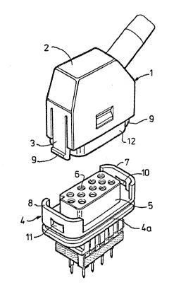
15 equipment. Fig. 1 shows, for example, sueh a eab]e assembly.
A cable eonnector 1 is provided with a housing 2 of insulating
material provided with resilient, spring loaded loeking lips 3.
The reeeptaele eonneetor 4 has a housing 4a of insulating
material with upright free wall parts 7 and 8 whieh are
20 separated by a distanee away ~rom a eentral part 5 provided
with eontaet plug soekets 6. Between these upright wall parts
7 and 8 and the eentral part ~ is a spaee adapted to reeeive a
eollar 12 of the eable eonneetor 1. 'Within this eollar 12 are pin
eontaets (not shown) whieh will be received by the plug soc1cets
25 S. When the eable eonneetor 1 is inserted into the reeeptaele
eonneetor 4, detents or bosses 9 on the end of the loeking lips 3
are first pressed inwards by the upright walls 7 and 8. When
the eable eonnector is fully seated in the receptacle eonnector,
the bosses 1 spring back into the recesses 10 and 11 to latch
30 the connectors together.
Receptacle eonnectors moun~ed or built into
eleetronie equipment cannot, however, always be provided
with the free upright wall parts 7 and 8. Such built-in
35 receptacle connectols 4 in fact may have a surrounding collar
20~3~73
- 2 -
12 such as shown in Fig. 2 which mut be fed in a close fit
through an aperture in a wall of the electrical equipment and
then mounted. The built-in receptacle connector 4 of Fig. 2
surrounds the pin contacts 14. Such a built-in receptacle
5 connector can also be in the form shown in Fig. 1 with plug
sockets but without the ~ree upright wall parts 7 and 8. There
are also other applications for which the wall parts 7 and 8
cannot be used.
~llmmarv of the ~nventiQn
To facilitate latching of cable connectors with such
recep~acle connectors mounted in electrical equipment, the
invention provides a separate lip loc.king ~rame which fits
15 around the above described peripheral wall of the central part
S of Fig. 1 or the collar 12 of Fig. 2 and ~,vhich can be locked
thereon. The locking îrame is also provided with receiving and
locking means for the above described locking lips of the cable
connector.
~ fter the receptacle connector is mounted in the
electronic equipment, the locking frame can be pushed onto the
projecting central part 5 (Fig. 1) or c:ollar 12 (Fig. 2) and locked
thereon. The receptacle connector is then provided with means
25 for accommodating the lips 3 and bosses 9 of the cable
connector 1.
To secure the 10cking frame on either the
peripheral wall of the central part 5 or the collar 12, the wall
30 or collar is preferably provided with boss guide and locking
means. The locking framé itself is provided with recessed
bosses for mating with these means.
EL-6088
2~7~
- 3 -
The boss guide means on the peripheral wall are
formed by tapered, slanted faces which extend tapering
outwards ~rom a line Iying within the peripheral wall at the
front side of the wall in the plug-in direction of ~he cable
5 connector into ~he plane of the peripheral wall, where the
guide faces merge into recessed locking faces Iying at right
angles to the peripheral wall. The lip loclcing frame is to Ihis
end provided with recessed bosses disposed on the inside wall
for mating with the boss locking faces in the peripheral wall.
The inside wall of the lip ]ocking frame is provided
with guide and locking faces for the bosses on the locking lips.
The invention will now be explained in greater
15 detail with reference to the drawings.
Brief D~scription of ~hç Drawin~
Fig. 1 shows the means described in the background of
20 the invention for locking a cable connector and a built-in
receptacle connector together;
Fig. 2 shows a conventional receptacle connector for
mounting to electrical equipment;
Fig. 3 shows a cable connector and a built-in receptacle
connector, the built-in connector being provided with a lip
locking frame according to the invention; and
Fig. 4 shows separately the built-in receptacle connector
and frame of Fig. 3.
FiL-608 8
4 2023773
I2etaile~1 ~escri~tiQn Qf tl~e mbn~im~
As described earlier, Figure l shows a receptacle
connector 4 for mounting to electronic squipment which is
5 provided with upright wall parts 7 and 8 containing recesses
10 and 11. The ~osses 9 of the locking lips 3, which are
disposed on the housing 2 of the cable connector 1, mate with
these recesses.
In a built-in recep~acle connector of the type sllown
in Fig. 2, the collar 12 must be inserted through a suitable
aperture in the wall of electronic equipment in order to mount
and fasten the receptac]e connector 4 to the wall. Upright wall
parts 7 and $ such as are shown in Fig. 1 are not, however,
15 possible, so that the cable connector I cannot be locked with
the lips 3.
This problem can be eli rnina~ed accorcling to the
present invention through use of lip loclcing frame 16 shown in
20 Figs. 3 and 4. This frame 16 can be locked on the outside wall
of the collar 17 of the built-in receptacle connector 4 whicll is
also shown in Figs. 3 and 4 (see particularly Fig. 4).
The lip locking frame 1~ for the cable connector 1
25 must, of course, also be locked on the built-in connector 4. Th;s
is accomplished by locking means disposed, on the one hand, on
the collar 17 and, on the other, on the inside wall of the lip
locking frame 16. The collar 17 is fitted with side faces 18
which extend outwards at an angle from the free front end of
30 the collar 17 into the plane of the outside wall of the collar.
This is followed by a recessed part l9 with a face at right
angles to the outside wall of the collar 17.
EI,-608B
` 2~237~3
The lip locking frame 16 is provided with bosses 20
with an upwardly slanting side 21 and a transverse face 22.
The bosses 20 are fitted in the lip loclcing frame 16 in the same
way as the faces 18 and 19 on opposite walls of the collar 17 as
5 shown in Fig. 4. When this locking frame 16 is pushed over the
collar 17, ~he bosses 20 are first pressed outwards bating walls
18, and after passing the edge of the face 19 they then spring
back. The lip locking frame 16 is then locked on~o the built-in
connector 4.
To ensure that the cable connector 1 with
conventional locking lips 3 and bosses 9 mate and latch with a
receptacle connector having the lip locking frame, the lip
locking frame 16 is provided with recessed parts 23 and 24
15 which do not run downwards as far the edge of the locking
frame 16, but end at a transverse wall 25 at right angles to the
plane of the locking frame 16. The collar 17 can be provided
with recessed parts 26, 27 in order to provide additional space
for the bosses 9.
When the cable connector 1 is now inserted into the
built-in receptacle connector 4, the bosses 9 of the locking lips
3 will be pressed inwards by the parts 23 and 24, until on
further displacement 8 the cable connector 1, these bosses 9
2S through the spring force of the locking lips 3 snap behind the
faces 25 of the lip locking frame. The cable connector 1 is
herewith now also locked on the built-in connector 4.
The present invention is not limited to the
30 embod;ment shown in Figs. 3 and 4, and modifications and
additions are possible without going beyond the scope of the
invent;on. ~or exan~ple, the faces 18 and 19 or recesses 26 and
27 can, of collrse, also be used in the central part 5 of Fig. l
EL-6088
`` 20~377~
- 6 -
containing plug sockets 6. The equipment or built-in connector
can be either the type with plug pins ~r one with plug sockets,
which also applies ~o the cable connector ma~ing therewith.
EL-6088
. ~