Note: Descriptions are shown in the official language in which they were submitted.
- 2024159
1-225675
S~N'1'~'1'IC RESIN WINDOW FOR
AUTOMOTIVE VEHICLES OR THE LIKE
The present invention relates to a window made
of synthetic resin, and more particularly to a synthetic
resin window which is suitable for automotive vehicles
or the like.
05 A synthetic resin window for automotive
vehicles is disclosed, e.g., in Japanese Utility Model
Application Laid-open Publication No. 61-32,808, as
being manufactured by an injection molding process.
The known synthetic resin window generally includes
a window body member of transparent or semi-transparent
synthetic resin, such as polycarbonate or acrylic resin,
as well as a frame member extending along the peripheral
edge of the body member and formed into a predetermined
shape which corresponds to flange of a relevant vehicle
body panel. Due to susceptibility of the synthetic
resin to scratches or the like damages, the outer
surface of the window body member is generally covered
by a hard coated film layer, while the outer surface of
the frame member is applied with a paint and covered by
an opaque coated layer of a desired color.
In this connection, Japanese Patent Application
Laid-open Publication No. 63-137,017 discloses a process
-2-
2024~S9
wherein a resin film formed with a hard coated layer
thereon is inserted into the cavity of an injection
mold, and a transparent synthetic resin is subsequently
injected into the cavity such that the resin film is
fusion-bonded to a sheet of the injected resin obtained
after it has been subjected to cooling and curing.
In this case, the resin film completely covers the
entire surface of the window body member. Furthermore,
Japanese Patent Application Laid-open Publication
Nos. 63-159,126; and 63-159,127 each discloses a process
wherein a hard coated layer is formed on the surface of
the window body member, and the window body member is
subsequently placed into the cavity of an injection mold
to integrally form the frame member along the peripheral
1~ edge of the window body member.
The abovementioned known synthetic resin window
proved to be advantageous particularly in its reduced
weight, but suffers from a problem of significantly low
rigidity as compared with conventional inorganic glass
windows. Thus, the synthetic resin window as mounted on
the vehicle body panel often exhibits undesirable
deformation or damage as a result of fastening force or
the like. The required rigidity of the synthetic resin
window might be realized either by increasing the
thickness of the window body portion itself, or by
providing reinforcing ribs on the frame portion.
20241~9
However, these solutions are not very suitable from
practical viewpoints that an increased thickness of the
window body portion would make it almost impossible to
achieve a reduced weight of the window as a whole, while
provision of the reinforcing ribs on the frame portion
more or less results in formation of undesirable sink
mark on the outer surface of the frame portion to
significantly deteriorate the appearance.
Moreover, the hard coated layer on the window
main body member tends to be readily separated due to
deformation or damage as a result of insufficient
rigidity of the window. Also, even when the hard coated
layer is formed on a primer layer, the hard coated layer
is not maintained in good adhesion with plasticized
1~ synthetic resin forming the frame member, e.g.
polyvinylchloride resin or polyurethane resin, so that
the frame member tends to be readily separated from the
window body member. Besides, the application of paint
to the frame member to form the opaque layer makes it
difficult to simplify the manufacturing steps.
Therefore, it is a primary object of the
present invention to eliminate the drawbacks of
conventional arrangement, and provide an improved
synthetic resin window which is light in weight and
rigid enough to prevent any deformation or damages of
the window as mounted in place.
2024159
Another object of the present invention is to
provide an improved synthetic resin window which is
excellent in weatherability and chemical resistance, and
which is capable of maintaining the hard coated layer
~ and/or frame member in good adhesion with the window
body member, thereby effectively preventing separation
of the hard coated layer and/or frame member from the
window body member.
To this end, according to the present inven-
tion, there is provided a synthetic resin window forautomotive vehicles or the like, comprising: a window
body member in the form of a sheet of transparent or
semi-transparent synthetic resin; a hard coated layer
covering and fusion-bonded to at least a substantial
1~ part of at least outer surface of said window body
member; a frame member of a synthetic resin formed
integrally with said body member to extend along
peripheral edge thereof; and a connection means arranged
between said frame member and outer surface of said
window body member.
The synthetic resin window according to the
present invention is provided with a hard coated layer
covering and fusion-bonded to the outer surface of the
window body member, and optionally formed on its inner
surface also, to realize a satisfactory scratch-proof
characteristic of the window body member as well as
2~24159
improved weatherability and chemical resistance.
Moreover, the positive connection between the frame
member and outer and inner surfaces of the window body
member makes it possible to maintain the hard coated
layer and/or frame member in good adhesion with the
window body member, and to thereby effectively prevent
separation of the hard coated layer and/or frame member
from the window body member.
There are many possibilities in realizing
a connection between the frame member and outer surface
of the window body member. For example, the connection
may be achieved by a core element which is integrally
connected to the window body member in a form-locking
manner from outer and inner sides thereof, and embedded
16 at least partly in said frame member. The core element
can be readily and stably maintained in integral
connection with the hard coated layer and also with the
frame member, and serves to effectively reinforce the
window as a whole and improve the mechanical strength of
the window, such as bending strength, fracture strength,
impact strength. Because the core element is embedded
at least partly in the frame member, even in the event
that the frame member is not maintained in good adhesion
with the hard coated layer, the frame member is stably
retained by the core element integrally connected to the
window body member in a form-locking manner.
2024159
In a window including a hard inorganic glass
plate, it is known to integrally form along the
peripheral edge of the glass plate a synthetic resin
frame member (or a molding member) in which a profiled
metal core element is embedded, as disclosed, e.g., in
Japanese Patent Application Laid-open Publication
Nos. 57-1,737; 58-73,681; 61-283,515; and 63-283,917.
However, the core element of such an arrangement serves
to reinforce the frame member itself, not the window
body member, and is not applicable to a synthetic resin
window since it is not maintained in good adhesion with
the window body member which is formed with a hard
coated layer thereon.
The connection of the window body member, frame
1~ member and core element with each other can be further
improved when the core element is formed with openings
through which the synthetic resin forming the frame
member is bonded with the window body member, when the
core element has projections which are pressed into the
window body member, and/or when the core element is
secured to the frame member by an adhesive agent.
Furthermore, when the core element is partly
exposed from the frame member, it is possible to readily
provide an aesthetically refined appearance of the
window.
As an alternative possibility, the connection
2024159
between the frame member and outer surface of the window
body member may include bare surfaces of the synthetic
resin forming the window body member, which are not
covered by the hard coated layer and which are directly
OG adhered to the frame member by an adhesive agent.
In this case, the frame member directly adhered to the
bare surfaces of the window body member which are not
covered by the hard coated layer can be retained in
place in a stable manner, with a minimized risk of its
separation. For maintaining a good adhesion of the hard
coated layer with the surface of the window body member,
the frame member may extend to cover the end region of
the hard coated layer on the outer surface of the window
body member.
1~ The window wherein the frame member is directly
adhered to the bare surfaces of the window body member
can be manufactured by a process including the step of:
inserting into the cavity of a first injection mold
a resin film which is formed with a hard coated surface
layer and which is smaller in size than the cavity, and
injecting into the cavity of the first injection mold
a transparent or semi-transparent synthetic resin to
form a sheet-like window body member with its surface
fusion-bonded with the resin film; placing the
peripheral edge of the window body member into the
cavity of a second injection mold, and injecting into
-8-
2~1-24159
the cavity of a second injection mold another synthetic
resin to form a frame member which is integral with the
window body member as being adhered to the bare surfaces
of the window body member.
Finally, in carrying out the present invention,
the hard coated layer may include a SiOx film layer
which may be formed by a plasma-enhanced chemical vapour
deposition process.
For a better understanding of the invention,
reference is taken to the accompanying drawings, in
which:
Fig. 1 is a front view of a side window for an
automotive vehicle according to one preferred embodiment
of the invention;
1~ Fig. 2 is a cross-sectional view taken along
the line II-II of Fig. l;
Fig. 3 is a cross-sectional view in an enlarged
scale, showing the hard coated layer in the region III
in Fig. 2;
Fig. 4 is a cross-sectional view similar to
Fig. 2, showing a modified embodiment of the hard coated
layer according to the present invention;
Fig. 5 is a cross-sectional view similar to
Fig. 3, showing the hard coated layer in the region V in
Fig. 4;
Fig. 6 is a perspective view the side window
2024159
according to the embodiment shown in Fig. l;
Figs. 7-9 are cross-sectionals view similar to
Fig. 2, showing different examples of the window
according to the embodiment shown in Fig. 1,
~ respectively;
Fig. 10 is a front view of a side window for
an automotive vehicle according to another preferred
embodiment of the invention;
Fig. 11 is a cross-sectional view taken along
the line XI-XI of Fig. 10;
Fig. 12 is a cross-sectional view showing the
step of molding the window body member shown in Figs. 10
and 11, and taken along the line XII-XII of Fig. 13;
Fig. 13 is a perspective view showing the
1~ window body member as molded;
Fig. 14 is a cross-sectional view showing the
step of molding the frame member shown in Figs. 10 and
11;
Fig. 15 is a schematic view explaining the step
of forming the SiOx sub-layer of the hard coated layer
in the window according to the present invention;
Fig. 16 is a cross-sectional view showing the
hard coated layer which has been formed by the step of
Fig. 15; and
Fig. 17 is a schematic view showing the device
for forming the SiOx sub-layer of the hard coated layer.
- 10 -
202ql59
The present invention will be explained below
with reference to some preferred embodiments shown in
the drawings.
Referring now to Fig. 1, there is shown
a synthetic resin side window according to one
embodiment of the present invention, which is for
an automotive vehicle. The window is designated by
reference numeral 1, and is made substantially of
appropriate synthetic resin by means of an injection
molding process, and secured to a relevant vehicle body
panel.
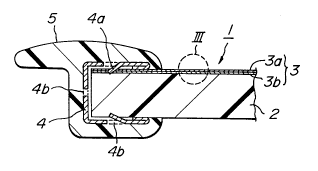
The window 1 includes a window body member 2 in
the form of a sheet of transparent or semi-transparent
synthetic resin, such as polycarbonate resin, polymethyl
1~ methacrylate resin or the like. The window body member
2 has an outer surface which is formed with a hard
coated film layer 3 to be explained hereinafter, as well
as a peripheral edge which is surrounded by a rein-
forcing core element 4 of an elongate profiled metal
body with a substantially U-shaped cross-section.
The core element 4 may be formed of a strip of stainless
steel, aluminum or other appropriate material, which has
been subjected to bending and press-shaping by means of
roll forming operation. The core element 4 is
integrally connected to the window body member 2 in
a form-locking manner from outer and inner sides
~24~9
thereof. More particularly, the core element 4 is
provided with a number of local projections 4a which are
pressed into the outer and inner surfaces of the window
body member 2. The window 1 further includes
a synthetic resin frame member 5 extending along the
peripheral edge of the window body member 2. The frame
member 5 is formed integrally with the window body
member 2 by an injection molding process, such that the
core element 4 is at least partly embedded in the frame
member 5.
As particularly shown in Figs. 2 and 3, the
hard coated layer 3 may be formed of a plurality of sub-
layers which are laminated with each other after
formation of the window body member 2 by an injection
1~ molding process. That is, the window body member 2 is
subjected to appropriate surface treatment to form on
its outer surface a hard coated sub-layer 3b consisting,
for example, of a siloxane- or acryl-based resin or a W
curing-type resin. The hard coated sub-layer 3b is then
covered by a SiOx sub-layer 3a. If necessary, a primer
sub-layer may be interposed between the outer surface of
the window body member 2 and the hard coated sub-
layer 3b.
In a modified embodiment shown in Figs. 4 and
5, the hard coated layer 3 is prepared prior to the
formation of the window body member 2. In this case,
2~24~g`
the hard coated layer 3 further includes a sub-layer 3c
in the form of synthetic resin film having a sufficient
compatibility with the synthetic resin forming the
window body member 2. The hard coated layer 3 including
the sub-layers 3a, 3b, 3c is inserted into the cavity of
an injection mold for molding the window body member 2,
before injection of the resin into the mold cavity.
After injecting the resin into the mold cavity and
subjecting the injected resin to cooling and curing,
a window body member 2 can be obtained including an
outer surface to which the synthetic resin sub-layer 3c
is fusion-bonded.
The frame member 5 is composed of appropriate
thermoplastic synthetic resin, such as polyvinyl
1~ chloride resin, polyvinyl acetate resin, ethylenevinyl
acetate resin, ionomer resin, etc, and is more resilient
and/or flexible as compared with the window body member
2. The frame member 5 may be formed by a process
including application of an adhesive agent to the outer
surface of the core element 4, subsequently placing the
peripheral edge of the window body member 2 into the
cavity of another injection mold, injecting the
thermoplastic synthetic resin into the mold cavity, and
subjecting the injected resin to cooling and curing.
By this, the frame member 5 is formed which is
integrally connected to the peripheral edge of the
-13-
2~241,5`g
window body member 2 with the core element 4 embedded
therein.
In this connection, as particularly shown in
Fig. 6, the core element 4 may be formed with a number
of openings 4b, some of which are obtained by providing
the projections 4a by means of stamping or the like,
through which openings the resin forming the frame
member 5 is directly and integrally connected to the
window body member 2.
In the synthetic resin window l according to
the abovementioned embodiment, the hard coated layer 3
covering and fusion-bonded to the outer surface of the
window body member 2 serves to realize satisfactory
scratch-proof characteristic and improved weatherability
1~ and chemical resistance of the window body member 2.
The positive connection between the frame member 5 and
the outer and inner surfaces of the window body member
2, in the form of a profiled core element 4, makes it
possible to maintain the hard coated layer 3 and frame
member 5 in good adhesion with the window body member 2,
to effectively prevent separation of the hard coated
layer 3 or frame member 5 from the window body member 2.
The core element 4 can be readily and stably
maintained in integral connection with the hard coated
layer 3 and also with the frame member 5, and serves to
effectively reinforce the window 2 as a whole and
-14-
20241Sg
improve the mechanical strength of the window, such as
bending strength, fracture strength, impact strength.
Because the core element 4 is embedded in the frame
member 5, the frame member 5 is stably retained by the
core element 4 which is integrally connected to the
window body member in a form-locking manner.
Moreover, due to the arrangement wherein the
core element 4 has projections 4a which are pressed into
the window body member 2 from outer and inner sides
thereof, while the core element 4 is formed with
openings 4b through which the synthetic resin forming
the frame member 5 is bonded with the window body member
2, and wherein the core element 4 is secured to the
frame member 2 by an adhesive agent, it is possible to
1~ achieve and maintain a stable integral connection of the
window body member 2, the core element 4 and the frame
member 5 with each other.
It is of course that various modifications may
be made to the abovementioned embodiment, as discussed
below with reference to Figs. 7-9 by way of examples
only.
First of all, in the example shown in Fig. 7,
the window body member 2 is provided with a peripheral
edge 2a of an increased thickness as compared with
remaining regions thereof, while the core element 4 has
its free edges 4c folded rearwardly toward the base of U
2024159
of its cross-section such that the folded free edges 4c
of the core element 4 are brought into mechanical
engagement with and behind shoulders which are formed
between the relatively thick peripheral edge 2a and the
remaining regions of the window body member 2.
In another example shown in Fig. 8, the core
element 4 includes an ornamental portion 4d which is
exposed from the frame member 5 and visible from
outside. The ornamental portion provides an
aesthetically refined appearance of the window 1,
particularly when it is of a color different from that
of the frame member 5. Moreover, the ornamental portion
4d is continuous with an upright portion 4e which also
is brought into mechanical engagement with and behind
1~ a shoulder between the relatively thick peripheral edge
2a and the remaining regions of the window body
member 2.
In still another example shown in Fig. 9, the
core element 4 is formed into an integral body of a hard
synthetic resin, such as fiber-reinforced plastics, and
includes projections 4f which are brought into engage-
ment with corresponding recesses 2b in the window body
member 2 to improve the integral connection between the
window body member 2 and the frame member 5.
Furthermore, although not shown in the
drawings, the hard coated layer 3 may also be formed on
20241~9
the inner surface of the window body member 2, while the
core element 4 or the frame member 5 needs not extend
along the entire peripheral edge of the window body
member 2.
Referring now to Figs. 10 and 11, there is
shown a synthetic resin side window according to another
preferred embodiment of the present invention, which is
for an automotive vehicle. The window is designated by
reference numeral 11, and is made as a whole of
appropriate synthetic resin by means of an injection
molding process, and secured to a relevant vehicle body
panel.
The window 11 includes a window body member 12
in the form of a sheet of transparent or semi-
1~ transparent synthetic resin, such as polycarbonateresin, polymethyl methacrylate resin or the like.
The window body member 12 has an outer surface which is
formed with a hard coated film layer 13 including sub-
layers 13a, 13b to be explained hereinafter, an inner
surface which is formed with a colored opaque layer 14,
as well as a peripheral edge 12a which is left uncovered
by the hard coated layer 13 or the opaque layer 14 to
expose bare surfaces of the synthetic resin on its outer
and inner sides. The window 11 further includes
a synthetic resin frame member 15 extending along the
peripheral edge of the window body member 2. The frame
2024159
member 15 is formed integrally with the window body
member 12 by injection molding process, and is adhered
to the bare surfaces of the window body member 12 on its
peripheral edge by means of an adhesive agent 16, if
necessary.
As clearly shown in Figs. 11, the hard coated
layer 13 may be formed of a plurality of sub-layers 13a-
13d which are laminated with each other. More
particularly, the window body member 12 is formed on its
outer surface with a base film sub-layer 13d of
a transparent resin having a sufficient compatibility
with the resin of the window body member 12, such as
polycarbonate resin, polymethyl methacrylate resin or
the like. The base film sub-layer 13d is covered by
1~ a hard coated sub-layer 13b consisting e.g. of
a siloxane-based resin, with a primer sub-layer 13c
interposed therebetween, if necessary. The hard coated
sub-layer 13b, in turn, is covered by another hard
coated sub-layer 13a of a SiOx film which may be formed
by PVD- or CVD-process in a manner known, perse.
The primer sub-layer 13c is composed of appropriate
material which is suitable for adhering the hard coated
sub-layers 13a, 13b to the base film sub-layer 13d, and
may be omitted when the base film sub-layer 13d is
composed of a polymethyl methacrylate resin.
One of the hard coated sub-layers 13a, 13b may
-18-
20241S9
be omitted, if necessary, though the combination of the
sub-layers 13a-13d laminated in the abovementioned
sequence proved to effectively provide satisfactory
functional advantages. Furthermore, the hard coated
layer 13 may be formed on the inner surface of the
window body member 12 also, as shown in Fig. 11.
Preferably, the peripheral edge 12a of the
window body member 12 with the bare surfaces on its
outer and inner sides has an increased thickness as
compared to the remaining regions of the window body
member 12, such that shoulders are formed by the
relatively thick peripheral edge 12a of the window body
member 12 along its junction with the remaining regions,
and these shoulders are brought into abutment with the
16 edge of the hard coated layer 13.
The frame member 15 is composed of appropriate
synthetic resin, such as plasticized polyvinyl chloride
resin, polyurethane resin, etc, and is more resilient
and/or flexible as compared with the window body member
2. When the synthetic resin of the frame member 15
exhibits an excellent compatibility to that of the
window body member 12, e.g. plasticized polyvinyl
chloride resin for the window body member 12 of
polycarbonate resin or polymethyl methacrylate resin,
the frame member 15 can be directly adhered to the bare
surfaces of the peripheral edge 12a of the window body
- 19 -
2~241~g
member 12. On the other hand, when the synthetic resin
of the frame member 15 exhibits a poor compatibility to
that of the window body member 12, e.g. polyurethane
resin for the window body member 12 of polycarbonate
~ resin or polymethyl methacrylate resin, the frame member
15 can be adhered to the bare surfaces of the peripheral
edge 12a of the window body member 12 by using an
appropriate adhesive agent. For maintaining a good
adhesion of the hard coated layers 13 with the outer and
inner surfaces of the window body member 12, the frame
member 15 preferably extends inwardly beyond the
relatively thick peripheral edge 12a of the window body
member, to cover and tightly contact with the edge
regions of the hard coated layers 13 on both surfaces of
- 16 the window body member 12.
The window according to the embodiment shown in
Figs. 10 and 11 can be manufactured by a process to be
particularly explained below. As shown in Fig. 12, the
process makes use of an injection molding device 20
which includes a cavity mold 21 and a core mold 22
defining a mold cavity 23 which corresponds in shape to
the window body member 11. There is prepared
a laminated film 13 corresponding to the hard coated
layer, having one end region in which is embedded
a magnetic strip 24a, 24b. Two sheets of laminated
films 13 are inserted into the mold cavity 23 such that
-20-
202~159
they are maintained in contact with inner surfaces of
the cavity mold 21 and the core mold 22, respectively.
The cavity mold 21 and the core mold 22 are each
provided with a magnet 25a, 25b embedded therein, and
the two sheets of laminated films 13 are positioned so
that their magnetic strips 24a, 24b are attracted by the
magnets 25a, 25b, respectively. The magnets 25a, 25b
are arranged close to gate 26 of the mold 20, and the
distance between inner surfaces of the cavity plate 21
and the core plate 22 in the resin inlet region 23a of
the mold cavity 23 is increased toward the gate 26 in
order to prevent the end regions of the laminated films
13 from being directly opposed to the gate 26.
The injection molding device 20 further
1~ includes a runner 27, a sprue 28 and a resin pool 29,
through which a transparent resin 30 in its molten state
is injected into the mold cavity 23 whereby the resin 30
is filled within the mold cavity 23, urging the
laminated films 13 against the inner surfaces of the
cavity plate 21 and the core plate 22. The injected
resin 30 is then subjected to cooling and curing, to
form a window body member 12 wherein the base film sub-
layers 13d of the laminated films 13 are integrally
fusion-bonded to the respective surfaces of the window
body member 12.
The window body member 12 so obtained is shown
-21-
20241S9
in Fig. 13, and is subjected to cutting along
a predetermined cutting line 31 to remove unnecessary
material in the resin inlet region 32.
In a subsequent frame formation step, as shown
in Fig. 14, use is made of another injection mold 40
which includes a cavity mold 41 and a core mold 42
defining a mold cavity 43. The peripheral edge of the
window body member 12 with bare surfaces of the resin is
inserted into the mold cavity 43 and the cavity mold 41
and the core mold 42 are clamped with each other.
If necessary, the peripheral edge of the window body
member 12 is applied with an adhesive agent 16 before it
is inserted into the mold cavity 43. The injection mold
40 further includes a runner 44, a sprue 45 and a gate
1~ 46, through which different resin 47 in its molten state
is injected into the mold cavity 43 to form a frame
member 15 which is directly and integrally connected to
the peripheral edge of the window body member 12.
Incidentally, the colored opaque layer 14 is
preferably formed in advance, e.g. by applying acryl
silicate-based paint to the resin film layer 13 and
subsequently injecting the resin to form the window body
member 12 and integrally fusion-bonding the film layer
13 to the surface of the window body member 12, though
it may be formed by applying a paint to the window body
member 12 after it has been molded.
-22-
2024159
Furthermore, although not shown in the
drawings, the hard coated layer 13 on the inner surface
of the window body member 12 may be omitted, and the
frame member 15 need not extend along the entire
peripheral edge of the window body member 12.
In the synthetic resin window 11 according to
the abovementioned embodiment, the hard coated layers 13
covering and fusion-bonded to the outer and inner
surfaces of the window body member 12 serve to realize
satisfactory scratch-proof characteristic and improved
weatherability and chemical resistance of the window
body member 12. The positive connection between the
frame member 15 and the outer and inner surfaces of the
window body member 12, i.e. the direct adhesion of the
1~ frame member 15 and the bare surfaces on outer and inner
sides of the window body member 12, makes it possible to
maintain the hard coated layer 13 and frame member 15 in
good adhesion with the window body member 12, and
effectively prevents separation of the hard coated layer
g 13 or frame member 15 from the window body member 12.
The hard coated layer 3, 13 in the window
according to the abovementioned embodiments can be
formed by various methods, such as PVD- or CVD-process
as explained hereinbefore. One efficient method,
however, is a so-called plasma-enhanced CVD process
using a high frequency magnetron cathode, wherein plasma
-23-
202~159
is confined by magnetic field to achieve a higher plasma
density, while high frequency voltage is applied to
excite the molecules themselves and thereby promote
decomposition of gas.
In this case, one preferred reaction to be
applied is shown by following formula (1):
SiH4+4N2O ~ Sio2+2H2o+4N2 ( 1 )
Alternative reactions are shown by following
formulae (2) to (5):
si(oC2)4 ~ SiO2+4c2H4+2H20 (2)
SiH4+5CO2+H2 ~ Sio2+5co+3H2o (3)
SiH2Cl2+2N20 ~ SiO2+2HC1+2N2 (4)
SiH4+2O2 ~ SiO2+2H20 (5)
More particularly, a flexible and transparent
resin film 3d (or 13d) is applied on its one surface
with a primer sub-layer 3c and/or siloxane-based hard
coated sub-layer 3b, if necessary, and is subsequently
formed with SiOx film sub-layer 3a by plasma-enhanced
CVD process. To this end, as shown in Fig. 15, the
resin film 3d is placed on a carrier 47 and moved to
a position where the film 3d is opposed to a high
frequency magnetron cathode 48 within a vacuum chamber
(not shown) and the carrier 47 is electrically connected
to ground. The pressure in the vacuum chamber is
reduced to, and maintained at approximately 10 to
10-3 Torr, preferably on the order of 10-2 Torr. While
-24-
~024159
injecting a small amount of Ar or N2 gas 49 into the
vacuum chamber, the cathode 48 is applied with a high
frequency voltage on the order of 10-20 MHz to generate
gas plasma in a space between the film 3d and the
cathode 48. On this occasion, the outer surface of the
film 3d is subjected to bombardment by the plasma of Ar
or N2 gas 49, while improving the flatness of the outer
surface at the same time. Supply of the Ar or N2 gas 49
is then stopped, and the vacuum chamber is now supplied
with a mixture gas in which SiH4 gas and N2O gas are
mixed with each other at a ratio of substantially 1:1 to
generate plasma, whereby the mixture gas undergoes
a chemical reaction to form a SiOx film 3a on the resin
film 3d to finish the hard coated resin film layer 3
16 (or 13).
There is shown in Fig. 17 one example of
a device for continuously forming the hard coated resin
film layer 3 (or 13). The device is designated as
a whole by reference numeral 50, and includes a supply
roll 51 for supplying the resin film 3d. The resin film
3d is continuously unwound from the roll 51 and passed
through rollers 52a-52e while it is heated by heater 53,
and subjected to bombardment (purification) on
a stationary earth member 54 by applying a high
frequency voltage to a cathode 55 and generating plasma
in a space between the resin film 3d and the cathode 55.
-25-
~024159
Subsequently, the resin film 3d is formed with SiOx film
layer 3a by plasma-enhanced CVD process on another
stationary earth member 56 by applying a high frequency
voltage to a cathode 48 and generating plasma in a space
between the resin film 3d and the cathode 48. The hard
coated resin film 3 so obtained is wound onto a winding
roll 57, and is subjected to trimming into a necessary
configuration corresponding to the window body member,
before the resin film 3 is inserted into the mold
10 cavity.
The abovementioned plasma-enhanced CVD process
is capable of uniformly forming the SiOx film at
relatively high speed and under relatively low
temperature, and particularly suitable for the surface
1~ treatment of various kinds of transparent or opaque
plastic articles, including automotive vehicle
components such as sun roofs, lens for illumination
lamps, finishers, wheel covers, etc., windows for
buildings, greenhouses, garages, refrigerators, display
cases, etc., as well as display screens for computers or
word processors.
It will be readily appreciated from the
foregoing detailed description that the present
invention provides an improved synthetic resin window
which is light in weight and rigid enough to prevent any
deformation or damages of the window as mounted in
-26-
2~24~59
place, and which is excellent in weatherability and
chemical resistance, and capable of maintaining the hard
coated layer and/or frame member in good adhesion with
the window body member, thereby effectively preventing
separation of the hard coated layer and/or frame member
from the window body member.
1~