Note: Descriptions are shown in the official language in which they were submitted.
2024219
ADHE$IVE TAPE ~u,~
R~C~POUND OF THE INVENTION
The present invention relates to a packing device, and more
particularly to an adhesive tape cutter.
A conventional adhesive tape cutter includes a handle
attaching thereto a metal base plate respectively securing
thereto a cutting device and a tape mounting carrying thereon an
adhesive tape roll. Cutting device includes a mounting piece
having an end fixed to base plate, a cutting edge fixed to
mounting piece, a roller having an end rotatably attached to the
base plate and a positioning plate fixing thereto the free end
of the mounting piece and rotatably fixing thereto the free end
of the roller for better mounting the mounting piece and the
roller on the plate. A cooperating plate provided on the handle
is held beneath the roller and urged against the roller by a
torsional spring and can cooperate with the roller to form
therebetween a clearance for passing therethrough the adhesive
tape from the roll so that in use, the roller can press tape
against the article to be applied with tape and then the cutting
edge desiredly cuts the tape.
The tape mounting includes a shaft having an end fixed to
the base plate and a free end having a flattened portion, a
carrier rotatably mounted on the shaft and carrying thereon the
roll, a positioner adjustably coaxially fixed into the shaft free
end, a pressing piece having an elongate hole engaging therein
the flattened portion, a stopper sleeved on the positioner, a
spring mounted between the pressing piece and the stopper for
biassing the pressing piece against the carrier, a washer mounted
between the carrier and the pressing piece and a sleeve mounted
between the carrier and the base plate.
202~219
Since the spring biasses the pressing piece against the
carrier through the washer, the tape roll will have a rotational
friction which is resulted by the frictions respectively occurred
between the washer and the pressing piece, the washer and the
carrier and the sleeve and the base plate and has an important
effect on the tape-applying operation in that if it is of an
enough magnitude, then the user can tightly, smoothly and per-
fectly apply the tape on the article to be tape-applied and can
neatly cut the tape so that the phenomena of a massed tape while
the user is applying the tape on an article and an inadvertent
tape slack while he is cutting the tape can be obviated.
Since the sleeve, the washer and the carrier are plastic,
even if the positioner is screwed into the shaft to the largest
extent the rotational friction of the tape roll is still insuf-
ficient in that the plastic itself has a lubricating effect. In
addition, the sleeve, the washer and the carrier get worn away
relatively easily (since in practice, the washer and the pressing
piece rarely relatively rotate) so that the rotational friction
of the tape roll is gradually reduced. Furthermore, if the
carrier is worn away to a serious extent, an entirely new cutter
is needed since the carrier cannot be independently obtained.
Still more, in continuous rapid packaging operation, the adhesive
tape easily escapes from the clearance between the roller and the
cooperating plate to result in a massed tape which not only will
cause a waste in tape and time but also is troublesome.
8UN~lARY OF THE INVFNTION
It is therefore a feature of one embodiment of the present
invention to provide an adhesive tape cutter capable of imparting
a relatively high rotational friction to an adhesive tape roll.
It is a further feature of an embodiment of the present
,~
, .
2021219
invention to provide an adhesive tape cutter having a tape roll
carrier incapable of being easily worn away.
It is an additional feature of an embodiment of the present
invention to provide an adhesive tape cutter in which the adhe-
sive tape cannot easily escape from the position which it is
supposed to reside in.
According to the present invention, an adhesive tape cutter
incudes a handle securing thereto a base piece respectively
fixing thereto a cutting device and a tape mounting mounting
thereon an adhesive tape roll, in which the tape mounting
includes as in the prior art a shaft, a carrier, a pressing
piece, a positioner, a stopper and an elastic member mounted
between the stopper and the pressing piece wherein the improve-
ment is that the tape mounting further includes two protecting
metal pieces respectively mounted between the base piece, and two
abrasive pieces respectively mounted between the base piece and
the carrier as well as the carrier and the pressing piece and the
respective one metal piece as well as the other metal piece and
the pressing piece.
BRIEF DB8CRIPTION OF THE DR~WINGS
The present invention may best be understood through the
following description with reference to the accompanying
drawings, in which:
Fig. 1 is a perspective view showing an adhesive tape cutter
according to the prior art;
Fig. 2 is an exploded view showing a tape mounting to an
adhesive tape cutter in Fig. l;
Fig. 3 is a sectional view taken along line 3-3 in Fig. l;
Fig. 4 is a front view showing an adhesive tape cutter in
Fig. l;
Fig. 5 is a perspective view showing a first preferred
202~219
embodiment of an adhesive tape cutter according to the present
invention;
Fig. 6 is an exploded view showing a tape mounting of an
adhesive tape cutter in Fig. 5;
Fig. 7 is a sectional view taken alone line 7-7 in Fig. 5;
Fig. 8 is a perspective view of a positioning plate of an
adhesive tape cutter in Fig. 5;
Fig. 9 is a front view showing an adhesive tape cutter in
Fig. 5;
Fig. 10 is a perspective view showing a second preferred
embodiment of an adhesive tape cutter according to the present
invention; and
Fig. 11 is a front view showing an adhesive tape cutter in
Fig. 10.
DET~TT~D DE8CRIPTION OF THE PREFERRED EMBODIMENT
Prior to describing the preferred embodiments of the present
invention reference will initially be made to Fig. 1 to 4 which
illustrate prior art devices.
A conventional adhesive tape cutter 10, as shown in Figs.
1-4), includes a handle 11 attaching thereto a metal base plate
-12 respectively securing thereto a cutting device 20 and a tape
mounting 30 carrying thereon an adhesive tape roll 40. Cutting
device 20 includes a mounting piece 21 having an end fixed to
base plate 12, a cutting edge 22 fixed to mounting piece 21, a
roller 23 having an end rotatably attached to base plate 12 and
a positioning plate 24 fixing thereto the free end of piece 21
and rotatably fixing thereto the free end of roller 23 for better
mounting piece 21 and roller 23 on plate 12. A cooperating plate
13 provided on handle 11 is held beneath roller 23 and urged
against roller 23 by a torsional spring (not shown) and can
cooperate with roller 23 to form therebetween a clearance for
202~19
passing therethrough the adhesive tape 41 from roll 40 so that
in use, roller 23 can press tape 41 against the article to be
applied with tape 41 and then edge 22 desiredly cuts tape 41.
5Tape mounting 30 includes a shaft 31 having an end fixed to
base plate 12 and a free end having a flattened portion 311, a
carrier 32 rotatably mounted on shaft 31 and carrying thereon
roll 40, a positioner 33 adjustably coaxially fixed into the
shaft free end, a pressing piece 34 having an elongate hole 341
10engaging therein flattened portion 311, a stopper 35 sleeved on
positioner 33, a spring 36 mounted between pressing piece 34 and
stopper 35 for biassing pressing piece 34 against carrier 32, a
washer 37 mounted between carrier 32 and pressing piece 34, and
a sleeve 38 mounted between carrier 32 and base plate 12.
Since spring 36 biasses piece 341 against carrier 32 through
washer 37, tape roll 40 will have a rotational friction which is
resulted by the frictions respectively occurred between washer
37 and pressing piece 34, washer 37 and carrier 32 and sleeve 38
20and base plate 12 and has an important effect on the tape-
applying operation in that if it is of an enough magnitude, then
the user can tightly, smoothly and perfectly apply the tape on
the article to be tape-applied and can neatly cut the tape so
that the phenomena of a massed tape while the user is applying
25the tape on an article and an inadvertent tape slack while he is
cutting the tape can be obviated.
Since sleeve 38, washer 37 and carrier 32 are plastic, even
if positioner 33 is screwed into shaft 31 to the largest extent
30the rotational friction of tape roll 40 is still insufficient in
that the plastic itself has a lubricating effect. In addition,
sleeve 38, washer 37 and carrier 32 get worn away relatively
easily (since in practice, washer 37 and pressing piece 34 rarely
4a
~.,
2024219
relatively rotate) so that the rotational friction of tape roll
40 is gradually reduced. Furthermore, if carrier 32 is worn away
to a serious extent, an entirely new cutter 10 is needed since
carrier 32 cannot be independently obtained. Still more, in
continuous rapid packaging operation, the adhesive tape 41 easily
escapes from the clearance between roller 23 and cooperating
plate 13 (as shown in Fig. 4) to result in a massed tape which
not only will cause a waste in tape 41 and time but also is
troublesome.
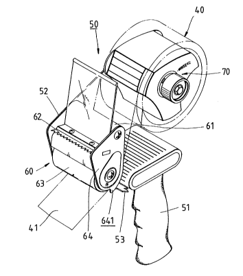
Referring now to Figs. 5-9, an adhesive tape cutter 50
according to the present invention includes a handle 51 securing
thereto a base plate 52 respectively fixing at the front and the
rear thereof a cutting device 60 and a tape mounting 70, and a
cooperating plate 53 mounted on handle 51 and urged by a tor-
sional spring (not shown) against cutting device 60 to form
therebetween a clearance for passing therethrough an adhesive
tape.
4b
'..~~
202~219
Tape mounting 70 includes as in the prior art a shaft 71, a carrier 72, a
positioner 73, a pressing piece 74, a stopper 75 and a spring 76 in which carrier 72
and pressing piece 74, however, have structures derrerellt from those of
co~ ,poning parts in the prior art. Carrier 72 capable of carrying thereon an
adhesive tape roll has a through hole 721 passing therelhlough shaft 71, 3 innerreinforcing ribs 722, and an end recess 723 forming a shoulder surface 724 evenly
provided with 3 holes 725. Pressing piece 74 is a metal ring and has a slot 741
slidably but unrotatably receiving therein a flattened fire end portion 711 of shaft
71. Tape mounting 70 further creatively includes two protecting metal pieces 77,78 respectively mounted between base plate 52 and carrier 72 as well as carrier 72
and pressing piece 74, and two abrasive pieces 81, 82 being made of asbestos
having a high coefflcent of abrasion and respectively provided between base 52
and metal piece 77 as well as metal piece 78 and pressing piece 74. Each of metal
pieces 77, 78 is generally annular and has 3 evenly disposed projections 771 (781)
so that projections 781 can respectively engage in holes 725 and projections 771can respectively engage with ribs 722 so that carrier 72 and metal pieces 77, 78can synchronously rotate. The rotational friction of carrier 72 is thus increased by
the provisions of metal pieces 77, 78 and asbestos pieces 81, 82.
Cutting device 60 includes as in the prior art a mounting piece 61, a cutting
edge 62, a roller 63 and a positioning plate 64 which, however, is structurally
dirrerenl from the collesl)onding element in the prior art in that plate 64 has a
lower extension 641 serving as a closing piece capable of pr~;vellling the adhesive
tape from escaping from the clearance between roller 63 and the cooperating
plate 53 so that the user can continuously smoothly obtain the adhesive tape from
the adhesive tape roll.
20242~9
As shown in Figs. 10 & 11, a second preferred embodiment of the adhesive
tape cutter 90 according to the present invention is structurally identical to cutter
50 with the exception that positioning plate 91 and cooperating plate 92 are
structurally slightly different from plates 64, 53 respectively in that positioning
plate 91 does not have a lower extension and cooperating plate 92 has an upper
projection 921 serving as a closing piece capable of closing the adhesive tape in
the clearance formed between roller 93 and cooperating plate 92 when the
present cutter 90 is in use.