Note: Descriptions are shown in the official language in which they were submitted.
VACWM FILL SYSTEM 2 0 2 4 3 0 4
TECHNICAL FIELD OF THE INVENTION
This invention relates to a vacuum fill system for
deaerating flowable materials for storage in a container,
and in particular, to a vacuum fill system for deaerating
and compacting flowable materials used in flexible bulk
containers.
BACKGROUND OF THE INVENTION
Containers used in the storage, transportation, and
dispensation of flowable materials have been around for as
long as civilization itself. The use of such containers,
however, has always been limited by (1) the weight,
density, and other physical properties of the material
being stored, and (2) by the process and type of container
used to store the material.
Traditional filling processes and containers have
long been encumbered by a simple phenomenon that has
exasperated consumers for decades - settling. Settling, as
any purchaser of a bag of potato chips knows, means the bag
is never completely filled when opened. This occurs due to
the settling of the product inside during its filling and
shipment. This simple settling phenomenon causes
tremendous economic waste each year because of the misuse
of storage space and container materials. This has been
particularly true in the storage, transportation, and
dispensation of flowable materials in semi-bulk quantities
- 2 - 2024304
such as grains, chemicals and other bulky substances stored
in flexible, bulk containers, such as those disclosed in
U.S. Patent Nos. 4,143,796 and 4,194,652.
It has long been known that the settling process is
caused by the natural aeration of flowable materials as the
materials are placed inside a container. As the container
is shipped to its final destination, the air escapes from
the aerated material mixture causing the product to compact
and reduce in volume. Thus, when the container is opened,
the flowable material has settled to the bottom of the
container, i.e. the bag of potato chips is only half full.
Any process or system, such as the present
invention, for storing materials in a container for
shipment that allows all of the container to be filled with
product and eliminates the excess air results in an
enormous cost savings. Indeed, the shipment of smaller
sized containers using vacuum sealed packages such as,
e.g., vacuum sealed coffee containers, has alleviated many
of the above problems of cost and time.
Although vacuum sealed packaging has proved to be an
efficient, cost-saving and consumer pleasing method of
shipping small quantities of goods, before now, it has been
impossible to apply such techniques into other areas of
storage, transportation and dispensation of flowable
materials. This has been particularly true in the market
for semi-bulk flowable materials.
-
3 2024304
The present invention, however, substantially
eliminates settling and the inherent problems associated
therewith by providing a vacuum filling system that
deaerates the flowable material during filling. The
present invention thus allows more product to be
transported in the same size container than is possible
using prior techniques.
Additionally, by utilizing all of the container
space, the present invention allows for the far more
efficient total use of all of the container materials and
space. No longer is money being spent for container
material that is not used. Therefore, the present
invention overcomes many of the difficulties inherent in
prior filling systems.
SUMMARY OF THE INVENTION .
The present invention relates to a vacuum filling
system for deaerating flowable materials, and in
particular, to a vacuum system for use with flexible bulk
containers used to store, transport and dispense flowable
materials in semi-bulk quantities.
The vacuum fill system of the present invention
generally comprises a first container for holding the
flowable material; means for controlling the flow of the
flowable material into the first container; means for
creating a vacuum in the first container for deaerating the
flowable materials; means for compacting the deaerated
4 2024304
material; and means for controlling the flow of the
deaerated, compacted flowable material from the first
container into a storage container for shipment.
In accordance with one aspect of the invention there
is provided a vacuum fill system for deaerating flowable
materials for storage in a container comprising: a hollow,
upwardly tapered container defining a predetermined
cross-sectional area for receiving and holding the flowable
materials; a discharge outlet attached to the container and
defining an opening having a cross-sectional area at least
as large as the largest cross-sectional area defined by the
hollow upwardly tapered container; means for controlling
the movement of the flowable material into the hollow,
upwardly tapered container; means for creating a vacuum in
the hollow, upwardly tapered container for deaerating the
flowable materials to temporarily suspend the flowable
materials to occupy a slightly greater volume than before
creation of the vacuum with the suspended materials having
a uniform cross-sectional area substantially the same as
the cross-sectional area defined by the hollow, upwardly
tapered container; means for returning the pressure in the
hollow, upwardly tapered container to atmospheric pressure
substantially instantaneously for compacting the deaerated
material into a substantially solid slug of material
occupying a cross-sectional area substantially identical
to, but slightly smaller than the cross-sectional area
defined by the hollow upwardly tapered container; means for
controlling the movement of the substantially solid slug of
~ 5 - 2024304
deaerated, compacted materials as a unitary form from the
hollow, upwardly tapered container; means for pressurizing
the hollow, upwardly tapered container to force the
substantially solid slug of deaerated, compacted materials
to fall as a unitary form from the hollow, upwardly tapered
container.
In accordance with another aspect of the invention
there is provided a vacuum fill system for deaerating
flowable materials for storage in a container comprising:
a hollow, upwardly tapered container defining a
predetermined cross-sectional area and having first and
second ends, the second end defining a cross-sectional area
at least as large as the largest cross-sectional area of
the hollow, upwardly tapered container; a first gate valve
and air cylinder attached to the first end of the hollow,
upwardly tapered container for controlling the movement of
the flowable material into the hollow, upwardly tapered
container; at least one vacuum line connected to the
hollow, upwardly tapered container; a plurality of valves
each connected to the vacuum line; vacuum means connected
to the vacuum line for creating a vacuum in the hollow,
upwardly tapered container for deaerating the flowable
materials to temporarily suspend the flowable materials to
occupy a slightly greater volume than before creation of
the vacuum with the suspended materials having a uniform
cross-sectional area substantially the same as the
cross-sectional area defined by the hollow, upwardly
tapered container; means for returning the pressure in the
- 2024304
hollow, upwardly tapered container to atmospheric pressure
substantially instantaneously for compacting the deaerated
flowable material into a substantially solid slug of
material occupying a cross-sectional area substantially
identical to, but slightly smaller than the cross-sectional
area defined by the hollow, upwardly tapered container; a
second gate valve and air cylinder attached to the second
end of the hollow, upwardly tapered container for
controlling the movement of the substantially solid slug of
deaerated, compacted materials as a unitary form from the
hollow, upwardly tapered container; and means for
pressurizing the hollow, upwardly tapered container to
force the substantially solid slug of deaerated, compacted
materials as a unitary form from the hollow, upwardly
tapered container.
In accordance with yet another aspect of the
invention there is provided a vacuum fill system for
deaerating flowable materials for storage in a container
comprising: a hollow, upwardly tapered container defining
a predetermined cross-sectional area for receiving and
holding the flowable containers; means for creating a
vacuum in the container for deaerating the flowable
materials to temporarily suspend the flowable materials to
occupy a slightly greater volume than before creating of
the vacuum with the suspended materials having a uniform
cross-sectional area substantially the same as the
cross-sectional are defined by the container; means for
returning the pressure in the container to atmospheric
k:.
,~
`-- 2024304
- 7 --
pressure substantially instantaneously for compacting the
deaerated material into a substantially solid slug of
material occupying a cross-sectional area substantially
identical to, but slightly smaller than the cross-sectional
area defined by the container; and a discharge outlet in
the container having a discharge opening with a
cross-sectional area at least as large as the largest
cross-sectional area defined by the container for
discharging the slug of deaerated, compacted material as a
unitary form from the hol~ow, upwardly tapered container.
In accordance with yet another aspect of the
invention there is provided a vacuum fill system for
deaerating and compacting flowable materials comprising: a
double chambered compaction container having first and
second ends and having an outer chamber and an inner
chamber with a space between the inner and outer chambers,
with the inner chamber connected to the outer chamber only
at the first end of the compaction container and with the
inner chamber defining a predetermined cross-sectional area
for receiving flowable materials therein; a discharge
outlet in the second end of the compaction container having
a cross-sectional area at least as large as the
cross-sectional area defined by the inner chamber of the
compaction container; means for controlling the flow of the
flowable materials into the compaction container; means for
creating a vacuum simultaneously in the space between the
inner and outer chambers and in the inner chamber to
deaerate the flowable materials; means for returning the
, .
. . ,
",
-
- 8 - 2024304
pressure in the compaction container to atmospheric
pressure substantially instantaneously for compacting the
deaerated flowable materials in the inner chamber into a
substantially solid slug of material occupying a uniform
cross-sectional area substantially the same, but slightly
smaller than the cross-sectional area defined by the inner
chamber of the compaction container; and means for opening
the discharge outlet to define an opening having a
cross-sectional area at least as large as the
cross-sectional area defined by the inner chamber of the
compaction container to allow the substantially solid slug
of deaerated, compacted material to fall as a unitary form
from the compaction container.
Operation of the vacuum fill system is simple and
easy. The flowable material is placed inside of the first
container. A vacuum is created through the use of a
plurality of valves and a conventional vacuum pump. After
sufficient deaeration of the flowable material is achieved,
the vacuum is released and the interior of the container is
returned to atmosphere pressure substantially
instantaneously causing the material to compact. The
compacted, deaerated flowable material then drops from the
first container into a flexible container for shipment. In
a second embodiment of the invention, compressed air is
introduced into the first container to force the compacted,
deaerated flowable material from the first container into
the flexible container.
2024304
g
By deaerating and compacting the flowable material
before filling the flexible container, through the use of
the vacuum fill system, the flowable material is presettled
and will not settle during shipment. Thus, the present
invention allows for complete utilization of the flexible
container, eliminating wasted space and allowing for the
shipment of more material without any increase in the
container volume. Therefore, the present invention has
numerous advantages over the prior art.
BRIEF DESCRIPTION OF THE DRAWINGS
A more complete understanding of the invention may
be had by reference to the following Detailed Description
when taken in conjunction with the accompanying Drawings,
in which:
FIGURE 1 is a partial sectional view of the vacuum
fill system;
FIGURE 2 is a partial sectional view of the vacuum
fill system illustrating its use with semi-bulk bags used
for containing flowable.materials;
FIGURE 3 is a partial sectional view of the vacuum
fill system illustrating the filling of the first container
with flowable material before deaerating;
FIGURE 4 is a partial sectional view of the vacuum
fill system illustrating the deaerated flowable material;
FIGURE 5 is a partial sectional view of the vacuum
fill system illustrating the deaerated flowable material
inside the storage container; and
FIGURE 6 is a partial sectional view of a second
embodiment of the invention.
2024304
- 10 -
DETAILED DESCRIPTION OF THE INVENTION
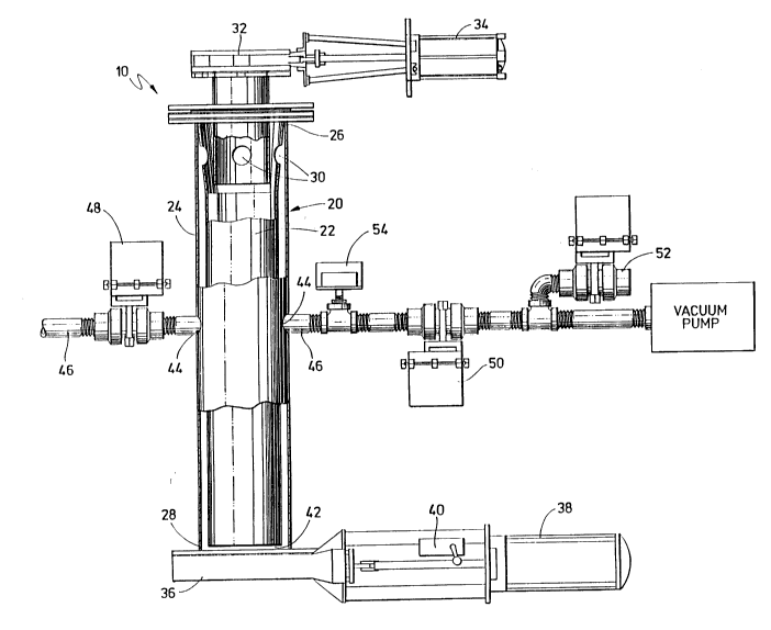
Referring tO FIGURE 1, the vacuum fill system 10 has
a hollow, cylindrical container 20, having inner and outer
chambers 22 and 24, respectively. Chambers 22 and 24 have
5first and second ends 26 and 28. The inner chamber 22
connects with the outer chamber 24 at the first end 26-of
the two chambers. In the preferred embodiment, the inner
chamber 22 has a plurality of openings 30 which allow for
the venting of air during use. The inner chamber 22 may
10also be made of a perforated or woven material to allow for
better evacuation and compaction.
Attached to the first end 26 of the hollow,
cylindrical container 20 and its inner and outer chambers
22 and 24 is a conventional knife or slide gate valve 32
15and associated air cylinder 34 which controls the opening
and closing of the gate 32. The slide gate valve 32 and
air cylinder 34 are of conventional types well known in the
art. When the gate valve 32 is in the open position,
flowable material flows through the gate valve 32 and into
20inner chamber 22 of the hollow, cylindrical container 20.
At the second end 28 of the hollow, cylindrical
container 20, there is a second slide or knife gate valve
36, which is normally of a slightly larger diameter than
slide gate valve 32. The slide gate valve 36 also has
25associated with it an air cylinder 38 and switch 40, both
-
- 11 2024304
well known in the art, which are utilized to open or close
the slide gate valve 36 to allow flowable materials to exit
from the hollow, cylindrical container 20 after deaeration
and compaction. Also at the second end 28 of the container
20, is a gap 42 between the bottom of the inner chamber 22
and outer chamber 24 of the container 20. The gap 42
allows air to vent and is utilized to help form a vacuum
during the deaeration process.
The outer chamber 24 of the hollow, cylindrical
container 20 has a plurality of openings 44 into which
vacuum lines 46 run. The vacuum lines 46 do not, however,
connect to the inner chamber 22. In the preferred
embodiment of the invention, there are at least two
openings 44 and two vacuum lines 46 running in opposite
directions. One of the vacuum lines 46 is connected to a
solenoid actuated butterfly valve 48 which in turn
connects to a conventional dust collector (not shown). The
second vacuum line 46 is connected to a series of solenoid
actuated butterfly valves 50 and 52, and from there to a
conventional vacuum pump (not shown).
Although any conventional vacuum pump may be
utilized with the present invention, the vacuum pump must
be capable of pulling a minimum of eighteen (18) inches of
mercury during operation. Also connected to the second
vacuum line 46 is a conventional pressure switch 54, which
- 12 - 2024304
is utilized to control the opening and closing of the
valves 50 and 52.
FIGURES 2 through 5 illustrate the operation of the
vacuum fill system of the present invention. Although the
vacuum fill system 10, illustrated in FIGURES 2 through 5,
is used in connection with the filling of a semi-bulk
container for handling flowable materials, it must be
understood that the present invention is capable of being
utilized with any type of container no matter how large or
small where it is desired to compact, deaerate and densify
the flowable materials for packing into a container for
shipment and storage.
Turning now to FIGURE 2, therein is illustrated the
initial start up position of the vacuum fill system 10.
In FIGURE 2, valves 32, 36, 48 and 50 are closed.
The flowable material 56 is contained within a conventional
holding/storage device 58, such as a hopper. The vacuum
fill system lO is connected to a semi-bulk bag 60 through
conventional means.
Turning to FIGURE 3, therein it is shown that the
hollow, cylindrical container 20 has been filled with
flowable material 56. In order to fill the hollow
container 20, valves 32 and 48 have been opened. This
results in the opening of slide gate valve 32 and the
venting of air through valve 48 to the dust collector
2û24304
- 13 -
during the filling process. Once slide gate valve 32 is
opened, the flowable material fills the inner chamber 22
up to the level of the openings 30. Openings 30 and gap
42 allow the dust to be vented to the dust collector
through valve 48 and vacuum lines 46.
The flow of flowable materials into the inner
chamber 22 is controlled either by weight or height level.
When the predetermined level or weight is reached, valve
32 automatically closes preventing the flow of further
flowable material 56 into the inner chamber 22 of the
hollow, cylindrical container 20.
At this time, valves 48 and 52 are also closed
automatically and valve 50 is opened. This creates a
vacuum in the space between the inner and outer chambers
22 and 24.
Turning to FIGURE 4, therein is illustrated that
flowable material 56 has been deaerated and compacted and
that the volume of material 56 is now significantly less
than when first introduced into the hollow, cylindrical
container 20.
When the air is initially evacuated from the inner
chamber 22, the volume of flowable material 56 actually
increases slightly as the internal air passes through it
and the vacuum is created. Thus, there is actually a
- 14 - 2024304
volume gain until the chamber is returned to atmospheric
pressure.
Once the vacuum reaches the necessary level to
achieve the desired deaeration of the flowable material 56,
valve 52 is opened immediately. Valve 52 must be opened
suddenly and fully in order to get a high impact on the
material 56 from the entering air. The impact of the
entering air compresses and compacts the deaerated,
flowable material 56, both axially and radially, due to the
internal low pressure previously created by the vacuum.
Subsequently, valve 36 is opened and the compacted,
deaerated flowable material 56 flows as a compact "slug"
of material into the desired container or, as illustrated,
bulk bag 60. Since the compacted and deaerated material
is highly densified and only drops a short distance before
entering the container 60, there is very little chance of
reaeration.
Finally, after the filling of the container 60 with
the flowable materials 56, slide gate valve 36 closes and
the vacuum fill system 10 is ready to begin a new cycle.
Referring now to FIGURE 6, a second embodiment of
the vacuum fill system 100 has a hollow, tapered chamber
120 having a first end 122 and a second end 124. Attached
to the first end 122 of the hollow, tapered chamber 120 is
a conventional knife or slide gate valve 126 and an
- 15 - 2024304
associated air cylinder 128 which controls the opening and
closing of the slide gate valve 126. The slide gate valve
126 and the air cylinder 128 are of conventional types well
known in the art. ~hen the slide gate valve 126 is in the
open position, flowable materials flow from an input source
130 through the slide gate valve 126 into the hollow,
tapered chamber 120.
At the second end 124 of the hollow, tapered chamber
120, there is a second knife or slide gate valve 132. An
associated air cylinder 134 and a switch 136 are utilized
to open or close the slide gate valve 132 to allow flowable
materials to exit the hollow, tapered chamber 120 through
a discharge chute 138 after deaeration and compaction. The
slide gate valve 132, the air cylinder 134 and the switch
136 are of conventional types well known in the art.
Line 140 runs into an opening 142 in the hollow,
tapered chamber 120 and is connected to a solenoid actuated
butterfly valve 144 which is in turn connected to a
compressed air source (not shown).
A vacuum line 141 runs into an opening 143 in the
hollow, tapered chamber 120, and is connected to a series
of solenoid actuated butterfly valves 146, 148, and 150,
and from there to a conventional dust collector 152. The
dust collector 152 has a knife or slide gate valve 151 and
an associated air cylinder 153 to allow discharge of dust
, *~, .,~
- 16 - 2 0 2 4 3 04
and particles from the dust collector. Mounted on top of
the dust collector is a fan 155. Connected to the vacuum
line 141 on both sides of the butterfly valve 150 is a
vacuum pump or high vacuum venturi 154.
As with the first embodiment of the invention,
although the vacuum fill system 100 is preferably used in
connection with the filling of a semi-bulk container for
handling flowable materials, it must be understood that the
vacuum fill system 100 is capable of being utilized with
any type of container, no matter how large or small, where
it is desired to compact, deaerate, and densify the
flowable materials for packing into a container for
shipment and storage.
Still referring to FIGURE 6, during operation of the
vacuum fill system 100, a semi-bulk bag 156 is connected
to the vacuum fill system 100 through conventional means
such as hooks 157 mounted in a frame 159. Support loops
161 on the bag 156 are placed over the hooks 157 to suspend
the bag below the discharge chute 138. A collar 163 on the
bag 156 is placed around the discharge chute 138 to prevent
spillage while filling the bag 156.
Before flowable materials are introduced into the
hollow, tapered chamber 120, the slide gate valves 126 and
132 and the solenoid actuated butterfly valves 144, 146,
and 150 are closed to allow evacuation of air from the
,~,
2024304
- 17 -
chamber 120. The slide gate valve 126 is then opened to
fill the hollow, tapered chamber 120 with flowable
material. The slide gate valve 126 is then closed, the
valve 148 remains open and the valve 150 is opened to
initiate evacuation of air from the filled tapered chamber
120. To further evacuate the filled tapered chamber 120,
the valves 146 and 150 are closed and the valve 148 remains
open drawing air from the chamber 120 through action of the
vacuum pump or high vacuum venturi 154.
Once the vacuum reaches the necessary level to
achieve the desired deaeration of the flowable material,
the valve 148 is closed and the valve 146 is opened to
suddenly vent vacuum line 141 and the tapered chamber 120
to the atmosphere, thereby compacting the deaerated
flowable materials within the tapered chamber 120.
The slide gate valve 132 and the valve 144 are then
opened to allow compressed air to be injected into the
tapered chamber 120, thereby forcing the flowable materials
as a compact "slug" of material from the tapered chamber
120 and into the desired container or, as illustrated, bulk
bag 156.
After the "slug" of material is ejected from the
tapered chamber 120 under the force of the compressed air,
the slide gate valve 132 closes and the vacuum fill system
100 is ready to begin a new cycle.
. . .
- 18 - 2024304
Although not shown, it should be understood that the
operation of the first and second embodiments of the vacuum
fill system lO and 100 may be performed either manually or
automatically through the use of conventional electronic
circuitry.
~ lthough preferred embodiments of the present
invention have been illustrated in the accompanying
Drawings and described in the foregoing Detailed
Description, it will be appreciated by those skilled in the
art that various modifications and rearrangements of the
component parts and elements of the present invention are
possible within the scope of the present invention.
..~
~.