Language selection

Search

Patent 2024870 Summary

Third-party information liability

Some of the information on this Web page has been provided by external sources. The Government of Canada is not responsible for the accuracy, reliability or currency of the information supplied by external sources. Users wishing to rely upon this information should consult directly with the source of the information. Content provided by external sources is not subject to official languages, privacy and accessibility requirements.

Claims and Abstract availability

Any discrepancies in the text and image of the Claims and Abstract are due to differing posting times. Text of the Claims and Abstract are posted:

  • At the time the application is open to public inspection;
  • At the time of issue of the patent (grant).
(12) Patent: (11) CA 2024870
(54) English Title: CLOTHES DRYER FILTER/HUMIDIFIER
(54) French Title: FILTRE/HUMIDIFICATEUR POUR SECHEUSE A LINGE
Status: Deemed expired
Bibliographic Data
(52) Canadian Patent Classification (CPC):
  • 34/16.5
(51) International Patent Classification (IPC):
  • D06F 58/20 (2006.01)
  • D06F 58/22 (2006.01)
(72) Inventors :
  • WALSH, ROBERT (Canada)
(73) Owners :
  • AQUA-VENT PRODUCTS, INC. (Canada)
(71) Applicants :
(74) Agent:
(74) Associate agent:
(45) Issued: 1993-12-14
(22) Filed Date: 1990-09-07
(41) Open to Public Inspection: 1991-03-28
Examination requested: 1991-02-21
Availability of licence: N/A
(25) Language of filing: English

Patent Cooperation Treaty (PCT): No

(30) Application Priority Data:
Application No. Country/Territory Date
413,440 United States of America 1989-09-27

Abstracts

English Abstract


Abstract of the Disclosure
An air filter and humidifier is attached to the back of a
clothes dryer. Exhaust air is ducted from the clothes dryer exhaust
port to the inlet port on the bottom of the filter/humidifier. From
there, the exhaust air is directed upwardly through the
filter/humidifier. A deflector redirects the exhaust air obliquely
downward against the surface of water within a container. The
water humidifies and filters the exhaust air. A variable amount of
the conditioned air escapes through an adjustable vent lid into the
home and the remainder is discharged through the filter/humidifier
and ducted outdoors. A hinged or removable lid allows the user
to remove the water container to add or replace water.


Claims

Note: Claims are shown in the official language in which they were submitted.


The embodiments of the invention, in which an exclusive
property or privilege is claimed, are defined as follows:
1. An air filter and humidifier adapted to be connected
between the upstream and downstream exhaust ducts of a clothes
dryer for conditioning its air exhaust comprising:
(a) an enclosure;
(b) a water container having an open upper end within
the enclosure;
(c) routing means within the enclosure for receiving the air
exhaust of a clothes dryer and directing it obliquely toward
the open upper end of the water container; and
(d) outlet means within the enclosure for discharging the
air exhaust directly into a room containing the enclosure.
2. The air filter and humidifier of claim 1, further comprising:
(a) means for mounting the device to the clothes dryer.
3. The air filter and humidifier of claim 1, wherein the outlet
means further comprises:
(a) a fitting adapted to be connected to the downstream
exhaust duct of a clothes dryer; and
(b) adjustable vent means for variably discharging a portion
of the conditioned air directly into the atmosphere of a room
containing the enclosure.


4. An air filter and humidifier adapted to be connected
between the upstream and downstream exhaust ducts of a clothes
dryer for conditioning its air exhaust comprising:
(a) an enclosure having a partially open top end and a
closed lower end;
(b) a water container having an open upper end within
the enclosure, the water container being removable from the
enclosure through the partially open top end;
(c) inlet means in the enclosure adapted to receive the air
exhausted at the upstream exhaust duct of a clothes dryer;
(d) inlet duct means extending vertically within the
enclosure adjacent to the container, the inlet duct means
having a lower end communicating with the inlet means;
(e) deflector means within the enclosure at a location
above the upper end of the inlet duct for directing air toward
the open upper end of the water container;
(f) fitting means in the enclosure for connection to the
downstream exhaust duct of a clothes dryer; and
(g) a lid covering the partially open top side of the
enclosure, the lid including vent means for discharging the
conditioned air into the atmosphere of a room containing the
enclosure.


5. The air filter and humidifier of claim 4, wherein the lid is
removable to allow removal of the container from within the
enclosure.
6. The air filter and humidifier of claim 4, wherein the lid is
hinged to allow removal of the container from within the enclosure.
7. The air filter and humidifier of claim 4, wherein the vent
means is adjustable to vary the amount of air exhaust discharged
into the atmosphere through it.
8. The air filter and humidifier of claim 4 wherein the vent
means comprises:
(a) first and second plates, each having at least one
aperture, the first and second plates being aligned so that at
least one aperture of the first plate and at least one aperture
of the second plate form at least one pair of coinciding
apertures; and
(b) an adjustment plate slidably fitting between the first
and second plates between a fully closed position and a fully
open position, the adjustment plate having at least one
aperture positioned to coincide with at least one pair of
coinciding apertures in the first and second plates only when
the adjustment plate is at its fully open position, whereby
discharge of the air exhaust into the atmosphere through the
coinciding apertures is permitted when the adjustable plate is
in its fully open position and discharge of the air exhaust into


the atmosphere is prevented when the adjustable plate is in
its fully closed position.
9. The air filter and humidifier of claim 4, wherein:
(a) the inlet means further comprises a hollow adapter
mounted to the lower end of the enclosure and adapted on
one side to be connected to the upstream exhaust duct of a
clothes dryer;
(b) the adapter having an open upper end communicating
with the lower end of the inlet duct to provide communication
between the upstream exhaust duct and the lower end of the
inlet duct; and
(c) the adapter being mountable to the enclosure in at
least two orientations, whereby the upstream exhaust is
receivable from at least two horizontal directions.


Description

Note: Descriptions are shown in the official language in which they were submitted.


2~2~
;
This invention relates to a filter/humidifier for connection to
the air exhaust of a clothes dryer.
~! The standard clothes dryer is a common device within the
home in which a great deal of energy is wasted when its warm
S exhaust is vented outside the home. The current concern for more
efficient use of energy has prompted various inventions relating to
energy conservation.
It would be desirable, in light of the high cost of energy, to
utilize the heat exhausted by the dryer to warm the home during
, 10 cold weather. However, most filters used in the exhaust of clothes
dryers are designed only to remove large particles. Since small
particles and dust are not filtered, the air is not suitable for
.~ discharge into the home. Therefore, an exhaust duct is typically
connected to the dryer's exhaust port to conduct the air exhaust
outside the home.
' The addition of conventional filtering to the dryer exhaust
system results in unacceptable back-pressure while failing to
satisfactorily remove dust particles from the exhaust air. Further,
even if such a filter were acceptable, it is desirable to discharge
the hot exhaust air into the home only in the colder winter
months. Accordingly, it would be necessary to change the exhaust
ducting from in-home exhaust to outside exhaust when approaching
summer and back to in-home exhaust when again nearing winter.

R13-008.P01


: :` `:: : ~, ` .: `' .
: , : . ~ - `` :

`
` 2~24~7~

,. .
This invention provides an improvement over previous clothes
dryer exhaust filtering systems by providing more effective filtering,
;~ greater convenience, and easy adjustment of the amount of
conditioned are entering the horne. Additionally, it humidifies the
S clothes dryer exhaust air. Humidification is desirable since winter
air and conventional home heating systems often produce a very
,~ dry atmosphere within the home during the winter months.
; The preferred embodiment of the invention is illustrated in
the accompanying drawings, in which:
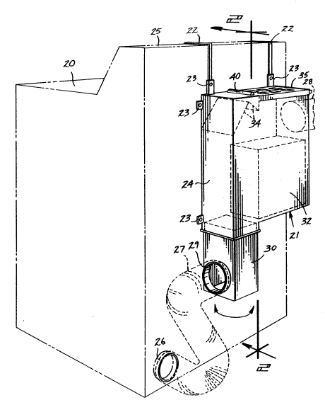
Fig. 1 is an isometric view of the rear of a clothes dryer
with the filter/humidifier attached;
Fig. 2 is a rear cut-away view showing the air flow through
the filter/humidifier;
Fig. 3 is a top view showing the vent lid; and
Fig. 4 is a side elevational view seen from the right in
Fig. 2.
The preferred embodiment of the invention is shown in
Figures 1, 2, 3, and 4. In Fig. 1, a filter humidifier 21 is shown
attached to the rear of a clothes dryer 20. Mounting straps 22
are bolted to mounting tabs 23 of enclosure 24. The straps 22
hook over the control panel 25 of the clothes dryer 20. The
filter/humidifier 21 can also be bolted directly to the back of the
dryer or attached to a nearby wall using mounting tabs 23. To

R13-008.P01 2

2 ~ 7 ~
.,.

,~
~, prevent scratching the dryer, the straps 22 can be rubber or plastic
coated.
An upstream exhaust duct 27 comlects the dryer exhaust port
26 to the filter/humidifier inlet port 29.
SReferring now primarily to Fig. 2, the enclosure 24 contains
an open water container 32 which is partially filled with water 33.
3 A rope handle (not shown) may be provided at the top of
container 32 to aid in its removal.
A hollow adapter 30 is attached to the bottom of enclosure
1024. The adapter 30 receives the air exhaust from upstream
exhaust duct 27 and routes the air upward to the lower end of an
inlet duct 31 within enclosure 24. Adapter 30 may be attached so
that its inlet port 29 extends to either side or to the rear of the
dryer/filter/humidifier combination.
15The in1et duct 31, essentially a hollow space between the
water container 32 and one upright side wall of enclosure 24,
routes the dryer exhaust air upwardly until it hits deflector 34.
The deflector 34 is comprised of a pair of flat surfaces which
routes the air obliquely downward and toward the surface of the
20water 33.
As the exhaust air hits the surface of the water 33, any dust
or lint is trapped in the water 33. Since the air is warm, the
water will also tend to evaporate, thereby humidifying the exhaust

R13-008.P01 3

2~2~i~7 ~


air. The filtered and humidified exhaust air escapes the enclosure
24 through either the vent lid 35 or through a downstream exhaust
duct 28 which is connected to the filter humidifier exhaust port 36.
Referring now particularly to Figures 2 and 3, the vent lid
35 allows a variable amount of conditioned air into the home and,
when hinged to an opened condition, allows removal of water
container 32. The vent lid 35 is attached to the enclosure by a
hinge 40. When closed, the vent lid 35 provides an essentially air
tight seal on the enclosure.
The vent lid 35 comprises an adjustment plate 43 which
slides between outer plates 41 to allow adjustment of the air flow.
Each plate 41 and 43 has apertures 44 which, when the adjustment
plate 43 is at its fully open position, align with one another and
correspond to allow air fiow through the vent lid 35. At its fully
closed position, the apertures 44 in the adjustment plate 43 are
offset from the apertures 44 in the outer plates 41. Thus, all air
flow through the lid is blocked. The adjustment plate 43 can be
placed at any intermediate position to provide partial
correspondence between the apertures, allowing partial air flow.
Adjustment plate 43 may be adjusted manually using the handle 45.
Any air which does not discharge through the vent lid 35
escapes through the filter/humidifler exhaust port 36 and the
downstream exhaust duct 28.

R13-008.P01 4


i:' ' . 1 : : . :. . . ~, , ,
Representative Drawing
A single figure which represents the drawing illustrating the invention.
Administrative Status

For a clearer understanding of the status of the application/patent presented on this page, the site Disclaimer , as well as the definitions for Patent , Administrative Status , Maintenance Fee  and Payment History  should be consulted.

Administrative Status

Title Date
Forecasted Issue Date 1993-12-14
(22) Filed 1990-09-07
Examination Requested 1991-02-21
(41) Open to Public Inspection 1991-03-28
(45) Issued 1993-12-14
Deemed Expired 2010-09-07
Correction of Expired 2012-12-02

Abandonment History

There is no abandonment history.

Payment History

Fee Type Anniversary Year Due Date Amount Paid Paid Date
Application Fee $0.00 1990-09-07
Registration of a document - section 124 $0.00 1991-01-30
Maintenance Fee - Application - New Act 2 1992-09-07 $50.00 1991-12-12
Maintenance Fee - Application - New Act 3 1993-09-07 $50.00 1992-10-02
Maintenance Fee - Application - New Act 4 1994-09-07 $50.00 1993-09-24
Maintenance Fee - Patent - New Act 5 1995-09-07 $150.00 1994-09-27
Maintenance Fee - Patent - New Act 6 1996-09-09 $75.00 1995-10-19
Maintenance Fee - Patent - New Act 7 1997-09-08 $75.00 1996-09-09
Maintenance Fee - Patent - New Act 8 1998-09-08 $75.00 1998-08-25
Maintenance Fee - Patent - New Act 9 1999-09-07 $275.00 2000-09-07
Maintenance Fee - Patent - New Act 10 2000-09-07 $100.00 2000-09-07
Maintenance Fee - Patent - New Act 11 2001-09-07 $100.00 2001-09-07
Maintenance Fee - Patent - New Act 12 2002-09-09 $300.00 2003-08-14
Maintenance Fee - Patent - New Act 13 2003-09-08 $100.00 2003-08-14
Maintenance Fee - Patent - New Act 14 2004-09-07 $325.00 2004-09-21
Maintenance Fee - Patent - New Act 15 2005-09-07 $225.00 2005-09-01
Maintenance Fee - Patent - New Act 16 2006-09-07 $225.00 2006-07-06
Maintenance Fee - Patent - New Act 17 2007-09-07 $225.00 2007-08-29
Maintenance Fee - Patent - New Act 18 2008-09-08 $425.00 2009-06-22
Owners on Record

Note: Records showing the ownership history in alphabetical order.

Current Owners on Record
AQUA-VENT PRODUCTS, INC.
Past Owners on Record
WALSH, ROBERT
Past Owners that do not appear in the "Owners on Record" listing will appear in other documentation within the application.
Documents

To view selected files, please enter reCAPTCHA code :


To view images, click a link in the Document Description column. To download the documents, select one or more checkboxes in the first column and then click the "Download Selected in PDF format (Zip Archive)" or the "Download Selected as Single PDF" button.

List of published and non-published patent-specific documents on the CPD .

If you have any difficulty accessing content, you can call the Client Service Centre at 1-866-997-1936 or send them an e-mail at CIPO Client Service Centre.


Document
Description 
Date
(yyyy-mm-dd) 
Number of pages   Size of Image (KB) 
Claims 1994-07-09 4 147
Cover Page 1994-07-09 1 27
Abstract 1994-07-09 1 31
Drawings 1994-07-09 3 80
Description 1994-07-09 4 170
Correspondence 2009-01-20 3 192
Correspondence 2002-10-07 2 130
Fees 2000-09-07 2 61
Fees 2004-09-21 2 44
Fees 2001-09-07 6 198
Correspondence 2003-09-11 1 16
Fees 2003-08-14 1 47
Correspondence 2003-08-14 1 45
Fees 1998-08-25 1 38
Fees 2000-09-26 1 43
Fees 2005-09-01 1 33
Prosecution Correspondence 1991-02-21 1 26
PCT Correspondence 1993-09-24 2 43
PCT Correspondence 1992-10-02 1 42
Office Letter 1991-04-24 1 21
Fees 2006-07-06 1 24
Fees 2007-08-29 1 26
Correspondence 2009-07-09 1 23
Fees 2009-06-22 2 113
Correspondence 2009-06-09 3 201
Fees 1996-09-09 1 45
Fees 1995-10-19 1 43
Fees 1994-09-27 1 62
Fees 1993-09-24 1 52
Fees 1992-10-02 1 40
Fees 1991-12-12 1 24