Note: Descriptions are shown in the official language in which they were submitted.
~~N~~~~
- 1 -
Attorney Docket: 1247/101 CA
APPARATUS AND METHOD FOR DATA CAPTURE BY MEANS OF A DETECTOR
ARRAY CONTAINING AT LEAST ONE DETECTOR ROW
Field of Invention
The present invention relates to methods and apparatus
for scanning and digitizing images.
Background Art
The digitizing of the scans of objects and pictures
produces signals obtained by means of data capture
equipment, that is known as a scanner. Digitizing is
necessary if a picture is to be stored in a computer and it
is desired to process the image. The two-dimensional analog
information obtained in a run is analyzed into picture
points or pixels, which have a differential grayscale. The
application of digitizing to image processing is extensive
and has come to embrace CAD, CAE, mapping, advertising, art,
simulation, and almost all spheres of chemistry and physics.
The requirements thereby placed on equipment are
correspondingly high. In seeking an image capture of
highest quality, information losses come directly and
inevitably to the fore. These losses arise through the
necessary splitting up of two-dimensional analog information
into individual pixels having a known size and predefined
distance from one another, wherein the pixels vary in
intensity over an established grayscale. In later image
processing in the computer there is undertaken an effort to
confine the information losses within tolerable limits by
means of mathematical algorithms.
Although today's applied mathematical algorithms bring
astonishing results, they cannot regain in the image signal
more information than was at hand in the object as scanned.
It must therefore be the goal to limit, through an optimal
data capture, the need for later image processing. This
problem is not new, and it has been worked on for a long
time.
- 2 -
From the German Patent 36 30 739 there is known a
method in which, during data capture of an image, a shifting
of the exposed detector array is effected. This shifting is
very small and permits image capture in the unrecorded
spaces between the individual detector elements of the
detector array. The doubled data cluster that has been
thereby obtained in scanning the object permits a better and
more precise reconstruction of the analog picture
information in the computer. The doubled data cluster,
however, certainly increases the processing time for both
the data capture and the processing in the computer.
In the same direction axe aimed attempts at increasing
the number of picture points (pixels) used for data capture.
Apart from the technological difficulties in the production
of a detector array having many detector elements, there
arises a further difficulty, at the least a diminution of
the area of a single detector which would normally produce a
stronger output, or in any case a longer one.
The scanning of bigger images is achieved in practice
through scanning of a number of smaller image portions.
These portions must be reintegrated and processed in such a
way that the raster scan of the first image is joined to the
raster scan of the second image, etc. In order to achieve a
uniform raster scan, there must be produced a uniform raster
in accordance with image processing methods appropriate to
the class of engineering involved by means of mathematical
algorithms, at great cost of time. The raster produced in
this manner has a deviation in comparison with a real raster
of a picture, since interpolation and weighting require
computation in the computer. All known methods of
digitizing of pictures have not satisfied up to now this
geametrical problem in the case of data capture.
A similar problem exists in the case of the analysis in
photogrammetry of aerial photos, as it is not always
possible to place the picture to be scanned in exactly the
same position arid orientation on the picture transport
without irreparable loss of time. Wholly apart from this
~(~2 ~~~~
- 3 -
there is the serious problem in photogrammetry of processing
stereo picture pairs. The individual pictures of such
picture pairs are distinguished on technical photography
grounds on the basis of so-called "canting," viz., they are
tilted slightly toward one another. In order to be able to
scan such picture pairs, it is necessary that the raster
scans in both pictures be in alignment.
In addition to the geometrical problem in the case of
data capture, there exists the problem of correcting
variations in sensitivity of the detector elements which
arise in production and even variations in the extent of
illumination, so that an unequivocal relation between the
detector signals and the grayscale of the scanned picture
elements is obtained.
This problem is addressed in the case of West German
patent 23 53 299 by a known scan apparatus in which during
the scanning of a standard background or of a white card
there is obtained a sensitivity profile of the detector
array. This is stored in digital form and then in operation
converted from its digital form into an analog form and
utilized for correction of the video information signal.
This method is involved and prone to error on account of the
double transformation of the sensitivity profile signal.
Further methods of correction are known from United
States Patent 43 17 134 and German Patent 36 30 739,
although these methods are not suited to insure a
sufficiently quick and precise correction.
Summary of the Invention
The present invention provides, a method of data
capture by means of a detector array containing at least one
detector row, in which an object being scanned and the
detector array move relative to one another, as well as an
apparatus for carrying out the method.
In a preferred embodiment, the invention provides a
method for data capture by means of a detector array having
at least one detector row, that enables, with one and the
- 4 -
same detector array, the optimal raster scan of the object
being scanned.
The method according to the invention has the advantage
that, through establishing the scan direction and the
corresponding angular position of the detector array by
information at hand in the object being scanned, the raster
scan is determined by criteria that are objective and always
reproducible. Through this approach it is insured that the
raster scan is largely independent of the position on the
apparatus of the object being scanned during the data
capture. This is especially advantageous in the data
capture of a series of pictures, since the same scan
direction can be selected for all individual pictures, so
that the succession of picture points (pixels) always
possesses the same alignment. This makes a later alignment
through the computer by means of mathematical algorithms
unnecessary, so that the accuracy of the scan signals
determines directly the accuracy of the scan.
This fact is of special advantage for the analysis in
photogrammetry of stereo picture pairs, as the raster scan
in both pictures can be selected with equal exactness
independently of the canting, so that the picture signal can
be analyzed directly and without the necessity of a
conversion.
In the method of scanning in accordance with the
invention the relative movement between object and detector
array can be effected continuously or discontinuously,
corresponding to the actual task and the actual
configuration of the detector array.
The data capture can work in the case of flat objects
either in reflected light or (for transparent objects) in
transmitted light. A data capture in transmitted light is
especially advantageous in the case of the analysis in
photogrammetry of aerial photos, as the developed film can
be used directly. This guarantees the optimal capture of
the information content of the picture.
Information contained in the object being scanned can
~~~,~ ~g~
- 5 -
serve in the establishment of the scan direction and thus
the raster scan. For instance, in the analysis of aerial
photos there are so-called "landmarks," viz., marked points
on terrain. These marks appear in aerial photos and are
used then as reference points for later analysis of the
pictures. Before the actual data capture, the aerial photo
is scoured for these reference points. These are known
beforehand to be found in specific picture segments, so the
search of the picture can be limited to these segments.
After the reference points are found through mathematical
algorithms or through an interactive work session with the
user, there is obtained from their picture coordinates the
orientation for the rotation of the detector array and for
the establishment of the direction of scan. In the case of
any interactive work session, these reference points can be
determined and established by working either on the basis of
a coarse overview scan of the entire picture or, e.g., With
the help of a separate print of the picture being scanned.
In a further embodiment of a method in accordance with
the present invention, scanning is achieved by movement of
the object in two coordinate directions perpendicular to one
another. Through this combined movement there results the
scan in the previously determined scan direction, with
respect to which the fixed detector array is so rotated that
its detector row lies perpendicular to the scan direction.
Calibration of the detector array benefits the capture
of data, and in a preferred embodiment may be done on a
repetitive basis, after the scanning of n swaths of the
picture. In this connection, it is advantageous that the
calibration be obtained using a calibration field having a
defined grayscale located outside of the object being
scanned, and the data pertaining to this field are stored in
the memory of a computer. In calibration of the detector
array, it is directed over a calibration field, which
displays at least two stripes with a defined grayscale. The
resulting detector signals are converted into digital
signals and corrected to corresponding values. The ordered
n n
t. Jr
~ef r. s; t 2J
- 6 -
correction factors for the single detector elements are
stored in the computer. In connection with a proper scan
run, the resultant analog picture signals are converted into
digital signals and after this corrected with the digital
correction factors in storage using digital computation.
In accordance with a preferred embodiment of the
apparatus of the invention, the photographic picture, for
example, the aerial photograph, constituting the object to
be scanned is arranged on a picture transport which is moved
by means of at least two computer-controlled drive motors
along a predetermined scan direction. The detector array
itself is rotationally oriented so that it can be brought
into the desired position. The rotation is achieved
preferably under computer control by a separate motor.
In order to insure an exact movement of the picture
transport relative to the fixed detector array, it is
advantageous to add on a servo loop employing sensed
position feedback. In this connection, the signal
indicative of the picture transport (used for sensed
position feedback) is used to provide synchronization of
data collection from the detector array.
The calibration fields for calibration of the detector
array are appropriately arranged outside of the picture
field. It is advantageous for the light source to be
arranged with an interchangeable filter, e.g., for the
digitizing of colored pictures.
Brief Description of the Drawings
The invention is more particularly described in the
following detailed description of the drawings represented
in Figures 1-3. In this connection, there are shown in
particular:
Fig. 1, a schematic representation of an exemplary
embodiment of an apparatus according to the invention;
Fig. 2, a view of the picture plane of the picture
transport of the apparatus according to Fig. 1; and
Fig. 3, an exemplary embodiment of an apparatus for
CA 02024893 1999-07-28
7 -
movement of the picture transport.
Detailed Description of Specific Embodiments
There is marked as item 1 a light source, which is
imaged by means of an optical system 2 at the light entrance
plane of a fiber optic bundle 3. After the exit from this
fiber optic bundle, the light is, by means of a prism 4,
reflected, and illuminates, via a lens 5, a pre-selected
area of the object 7 arranged on the picture transport 6.
l0 This object can be, in the example shown, an aerial photo
r transparency. By means of an optical system 8, the
illuminated area of the picture 7 is imaged on a detector
array 9, which in the example represented can be a linear
array. Between the optical system 2 and the fiber optic
bundle 3 is arranged a filter wheel 10, which contains
several light filters which can be color ~or attenuating
filters, or a combination thereof. The filter wheel 10 is
moved into a pre-selected position by means of a motor 11.
The picture transport 6 is, by means of two motors 12
and 13, moveable along two fixed coordinate directions
perpendicular to one another. A further motor 14 serves to
rotate the detector array 9 into a pre-selected angular
position.
The detector array 9 produces electrical signals whose
magnitude depends on the intensity of the light transmitted
through the picture 7. The signals produced by the array 9
proceed to an interface 15. From there they are led to a
central computer 16.
Item 17 identifies a further computer which controls
both the light source 1 and the filter wheel 10 in order to
establish the optimal illumination of the scanned. object.
The computer 17 controls, furthermore, the motors 12
and 13 for the drive of the picture transport as well as the
motor 14 for rotation of the detector array 9 into a pre-
selected position. In addition, the computer 17 utilizes
the signal pulses indicative of the position of the picture
transport (used for sensed position feedback) to calculate
n
a~ ~
_8_
and output a clock signal to the detector array to trigger
data collection.
The picture 7 to be scanned lies, during data capture,
on the flat transparent surface 20 of the picture transport
6. Item 21 is a transparent cover, which presses the
picture firmly onto the support surface 20, so as to assure
during data capture the flattest possible surface of the
picture.
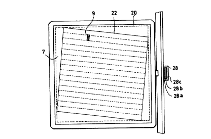
In Figure 2 there is represented a view of the support
platen 20 of the picture transport 6. On this support
platen lies the picture 7 being scanned. In the first
instance, in the previously described manner, a first data
capture is carried out so that, for example, the landmarks
contained in the picture 7 are established. These signals
are then used automatically by digital computation or
interactively to fix the scan direction, which is identified
in Figure 2 as item 22. At the same time as the
determination of the scan direction, the detector array 9 is
rotated by means of a motor 14 via computer 17, so that its
detector row lies exactly perpendicular to the direction 22
of scan.
In the case of a succeeding scan run, the picture
transport 6 is moved by means of the motors 12 and 13 so
that the picture 7 indicated inside of the boundaries in
Figure 2 moves in the scan direction relative to the fixed
detector array 9. Then the length of the detector row 9 is
encountered as the length of the scanned image is scanned
swathwise, so that the breadth of the swath corresponds to
the length of the image of the detector array. These swaths
are indicated in Figure 2 by dashed lines. The movement of
the picture transport 6 in the scan direction 22 results
from operation of both rotation motors 12 and 13 by the
computer 17. As Figure 3 shows, both motors 12 and 13 drive
the picture transport over spindles 24 and 25 in two
coordinate directions fixed at right angles to one another
that are identified as X and Y. Through appropriate
operation of the motors 12 and 13, each pre-selected scan
ha ~ to '3 ~~
- g -
direction is precisely tracked.
With each one of the rotation motors 12 and 13 there is
contained a position-governing arrangement (26 or 27), with
respect to which signals are directed to the computer 17.
To this is added a servo loop, which, utilizing feedback of
impulses derived from translation along the X- and Y-axes,
ensures that the drive of the picture transport 6 follows
uniformly and precisely in the pre-selected scan direction.
Outside of the scan field is arranged a calibration
field 28, which is to be seen in Figures 2 and 3. Before
the proper scan run or even after passage of a pre-
determined number of picture swaths, the picture transport 6
is moved so that the calibration field 28 is imaged on the
detector array 9. This calibration field contains 3
stripes, 28a-28c, with different gray levels. During the
calibration run correction factors are obtained which
compensate the differential sensitivity of single detector
elements and ultimately inequalities of the illumination.
The correction factors axe stored in the interface 15 as
digital values. In the case of proper scan runs, the
resultant analog picture signal is converted into a digital
signal and multiplied in the interface 15 by the digital
correction factors.
The apparatus represented in the figures 1-3 finds
especially advantageous application to photographic scanning
of aerial photographs, especially stereo aerial photographs.
In this case, the negative of the aerial photograph is used
directly as the scanned item 7.