Note: Descriptions are shown in the official language in which they were submitted.
~d ~? ~d c~ '",Fj c )
ONE-STEP METHOD FOR FORMING A PRESSURE-SENSITIVE
ADHESIVE TRANSDERMAL DRUG DEVICE AND APPARATUS THEREFOR
BACKGROUND OF THE INVENTION
The present invention relates to drug-containing
pressure sensitive adhesive containing on one side, a backing)
and on the other side. a release liner, (sometimes called a
transdermal drug delivery device) and morn particularly, to a
method and apparatus for forming a transdermal drug device and
scoring its liner to permit the liner to be easily removed from
the adhesive carrying drug in one step.
Many apparatus and methods hava been devised for
continuously or intermittently scoring a release Liner for use
with transdermal drug-containing adhesive in order to permit
the liner to be, easily removed from the device immediately
prior to its being used. One such method is to completely cut
through the release liner. However, t!~e typical procedure for
the preparation of a transdermal drug delivery device is as
follows: First, a dilution or suspension of the adhesive
a C'.. ~ "' '7
if ii ~~ ~> ~J ' ~..7
containing the drug is poured onto a Flexible plastic intended
to function as a disposable release liner. Next, a
non-releasable backing material is applied over the adhesive.
The result is a web containing an adhesive with a backing on
one side and a disposable release liner on the other. A shaped
device is then formed by a peripheral cutting through a11
layers oP the resulting .reb. The disposable release liner is
then removed and a second, scored release liner is attached to
the transdermal adhesive.
Alternatively, the liner can be first scored and
assembled with the adhesive and the backing and then the
assembly cut to the desired dimensions.
The purpose of the multi-step prJcedure for applying
the backing and the release liner to the adhesive containing
the drug is to avoid the problems encountered when a scored
release liner is used in processing. IF such a completely cut
release liner is used prior to coating) tha adhesive can pass
through the release liner at the score causing equipment
problems, cracking, separation and heat damage.
These prior art methods suffer ~r..~m the disadvantage
that the procedure for applying the release liner requires many
steps. It thus has a tendency to be more expensive~in large
scale manufacturing than a procedure ~~rhich ~rould involve newer
steps.
-2-
r,-~ :~, :/2 e' !;
!;~ f~d e> ~i ~::j -.
SUMMARY OF THE INVENTION
The present invention overcomes the difficulties arid
disadvantages associated with prior art devices by providing a
method and device therefor for simultaneously cutting an
assembled transdermal device from a web comprising a backing, a
drug-containing adhesive and a release liner.
This invention is accomplished by providing cutting
devices sized to cut completely through the periphery of the
assembled web to form the transdermal device, and also sized to
only cut or score the release liner at a position intermediate
to the periphery of the device. The intermediate cut does not
extend to the adhesive or the non-releasable backing.
These advantages are accomplished by the use of a
cutting device having the configuration of .he device to be cut
with an exterior cutting element sized to form the transdermal
device, and the interior cutting element sized to cut only
through the release liner.
BRIEF DESCRIPTION OF THE DRAWINGS
Fig. 1 is a plain view of the devi;.~.
Fig. 2 is a cross section of the device along line 2-2.
Fig. 3 is a cross section of the device taken along
line 3-3.
Fig. 4 is a cross-section of the drug delivery device
in the web form prior to cutting.
-3-
5Fa v5 '._s :_i <.8
DETAILED DESCRIPTION OF THE PREFERRED EMHODI~'ZENT
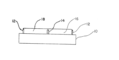
The preferred embodiment of the cutting die is
illustrated in Fig. 1 in the form a support surface 10 having a
two-dimensional cutting element 12 shown as having a generally
elliptical configuration ~aith a one-dimensional central cutting
element 14 of generally linear shape; and a pair of recesses 16
and 18 formed by the cutting elements 12 and 14. The web of
the transdermal bandage is adapted to lay across the rigid
support surface shown in Fig. 2 covering the entire well area
formed by the cutting element 12. The cutting element 12 is
sized with respect to the web so as to completely cut through
the web, while the cutting element 14 is sized so as to cut
only the release liner. The web is appl'_ed with the release
liner facing the support.
Referring to Fig. 2, a cross section of the device
taken along lines 2-2, the sizing of the cutting elements 12
and 14 is such that the difference in height between cutting
element 12 and cutting element 14 is equal ~o the height of the
release liner. Thus, cutting elements 12 and 14 are sized so
that cutting element 12 is substantially the height of the web,
while cutting element 14 is the height of the transdermal web
less the height of a11 layers other than the release liner.
Fig. 4 shows a transdermal web in lateral cross
section prior to being cut. Layer 22 is the backing material,
layer 24 is the adhesive containing drug and layer 26 is the
-4-
n, : '1 ~ ,'? : t, !'1
ld '!'! ~d zv '~J~ :7 !~
release liner layer. For purposes of this invention, the
release liner layer prior to being cut is available as a web or
a continuous roll prepared by applying the fluid adhesive to
either the release liner 26 or the backing material 22, then
applying either the backing material 22 over release liner 26,
respectively, to the or_her side of the adhesive containing the
drug. The stock or web 20 is then placed on the solid support
with the release liner 26 facing the cutting elements 12 and
14. The transdermal device is then punched out with a die
cooperating with the solid support.
The solid support and the die are preferably made of
steel or relatively incompressible rigid material. It can be
machined from a solid member or cast with a generally desired
configuration and then machined to the prwper dimensions. In
any event, the outer cutting element 14 generally has a
circumference of from 3 to 40 arm and preferably from 7.9 to
17.7 mm, depending on the surface area needed for delivery of
the drug and a radius of .48 to 6.4 mm and preferably 1.3 to
2.8 mm, again depending on the appropriate radius for the drug
to be delivered. as is known to those skilled in the art.
Any configuration of cutting ele:~~ents 12 and 14 is
possible; however, superior results have been found where
cutting element 12 has a single .slanted face directed toward
the periphery of the template, and cutting element 14 has a
dual slant terminating in a central apex.
-S-
i :~ .~ e3
(~J a
Cutting elements 12 and 14 are sized so that cutting
element, in cooperation with the web, passes completely through
the web, while cutting element 14 passes only through the
release liner. In general, cutting element 12 is from 100 to
1500 in height, and preferably 900 to 1000, and more
preferably, 930 to 950 microns, although obviously the height
of the cutting element is dependent upon the height of the web.
Again, the cutting element 14 is preferably 100 to
1S00 microns and more preferably 850 to 950 microns and even
more preferably 92S to 945 microns, although again the height
is totally dependent on the thickness of the release liner.
For example, with a stock of 10 microns in thickness where the
release liner is 4 microns in thickness, cutting element 12
would 937 in height while cutting element 14 would be 93S
microns in height.
Obviously, the cutting element 14 has to extend
sufficiently into the release liner to cause a score) but not
sufficiently to also cut the adhesive drug-containing layer.
Although the apparatus of this invention can be used
with release liners that are as flexible, as more flexible than
or equally flexible as the combination of the backing and
adhesive layer, .it is desirable to use a backing having the
same order of frangibility as the release liner, so that the
" force needed to cut the entire device and at the same time
score only the release backing could be about the same.
-&-
Ed ~ ~ h ~:.~ ~r :.a c.~
The foregoing arrangement allows the outside cutting
rule to cut complete through a11 layers of the transdermal
device while the center cutting rule only cuts through the
release liner. The device further can have the peripheral
cutting device extending on one side only toward the periphery,
thus permitting straight lines on the interioL surface of the
cutting element. The dual edge of the intermediate cutting
device avoids uncut material in the area. Other variations of
the instant device mill be apparent to one skilled in the art.
-?-