Note: Descriptions are shown in the official language in which they were submitted.
- 1 - 2025338
The present invention relates to a feedback control
system which controls the output of a controlled object
according to a control variable command.
Feedback control has so far been applied to control
the output of a controlled object in response to each of
control variable commands. The control computation unit
devised to undertake feedback control renders service in
two different types -- an analog computation type using
an operational amplifier, and a digital computation type
wherein a microcomputer or the like is utilized.
Feedback control through analog computation is
characterized by serial control computation in response
to the command of a controlled variable or the signal
thereof to be feedback. In view of this, analog
computation-combined feedback control is otherwise
called a continuous-time system. Meanwhile, digital
computation-introduced feedback control is implemented
via control computation in response to the signal
sampled at a certain interval of time out of some
controlled variable signals. Therefore, the latter
feedback control is referred to as sampled data system
control.
A continuous-time system undergoes and incon-
venience that the time required before the controlled
output gets settle after the occurrence of a control
variable command fluctuation and/or a disturbance, that
is, the settling time is long. Meanwhile, the control
... ..
2Q2533~
`
- 2
referred to above provides an advantage that the
response characteristic thereof is hardly sub;ect to
change regardless of parametral fluctuations of a
controlled object.
Now, with sampled data control, it is practical to
settle the controlled variable within a finite time.
However, the control remarked above concurs with a
stepwise change of a manipulated variable, whereby an
unfavorable consequence is brought about to the
controlled ob;ect involved. Assuming the case of motor
control, if there is witnessed a large magnitude in the
stepwise change of a manipulated variable command, a
machine, the load coupled to the motor concerned will
experience intensive shocks.
Further with sampled data control, control
computation is effected, following the signal just
sampled by a sampler. Such being the case, if the
signal from a control variable detector for feeding back
the control variable at the instant of signal sampling
comes to carry noises (external disturbance), control
performance is affected greatly by the disturbance.
Furthermore, where integral gain Ki, proportional
gain Kp, and so forth of the control computation unit
are optimally selected for the controlled ob;ect
involved, it is feasible to settle the controlled
variable within a finite time. But in the event the
proper relationship between a selected control gain and
~0~!~33~
`
the controlled object concerned is lost due to some
change on the part of the controlled system,
controllability declines greatly, let alone becoming
incapable of showing a finite time-settling response.
Top cope with the above-quoted problem, it is
conceivable that the interval of sampling is decreased
so that the controlled variable will be settled through
a relatively large number of samplings, thereby to
fabricate such a control system robust against
parametral fluctuations of the controlled object
involved. ThiS, however, results in rendering the
control computation unit configuration complex, with the
number of parameters (gains) requiring adjustment within
the control computation unit getting increased.
Moreover, such a system will therefore not allow ease of
realization.
The object of the present invention is to provide a
feedback control system devised with the above-remarked
points well reflected, featuring not only smoothness of
a continuous-time system as well as robustness against
parametral fluctuations of the control system but also
capability of finite time-settling with sampled data
control.
The present invention has a control computation
unit of which the feedback control system is comprised,
added with a delay element plus the integration and
proportional elements which have so far been applied.
- 20~338
.
-- 4
The delay time of this delay element depends either
settling time (namely, the time for the control variable
to follow changes in the control variable command) or
the time at which the control variable is restored to
the value given by the control variable command when the
controlled object has gone through an external
disturbance. In other words, in case the control
computation unit, the controlled object and/or the
control variable detector are confronting a computation
delay time, a dead time, and a detection delay time,
respectively, then the delay element's delay time is
selected as being equal to each of the above or the sum
of these delay times.
The present invention wherein the control
computation unit has a delay element with the delay time
equal to the time of basic settling added, is thus
characterized by an additional function to negate the
response which, according to a conventional control, is
inclined to continue after the time until which due
settling is desired to be completed, whereby said
control computation unit is allowed to settle the
response at the timing coinciding with the time of
necessary timing.
Thus, the application of the present invention for
a continuous-time system enables to realize finite
settling-time response control which is a feature of
sampled data control. Meanwhile, use of the present
2~33~
-- 5
invention for sampled data control renders practicable
to achieve the control not only smoothness, but also
against parametral 1uctuations, which is a technical
feature of a continuous-time system, with finite time-
settling control maintained serviceable.
This invention can be more fully understood from
the following detailed description when taken in con-
~unction with the accompanying drawings, in which:
Fig. lA is a block diagram showing one basic
configuration of the feedback control system of the
present invention;
Fig. lB is a block diagram showing another
configuration of the feedback control system of the
present invention;
Fig. 2 is a system configurational diagram showing
one preferred embodiment of the present invention;
Fig. 3 is a response waveform which the preferred
embodiment of the present invention exhibits;
Fig. 4 is another response waveform coinciding with
the occurrence of a parametral fluctuation of the
preferred embodiment of the present invention;
Fig. 5 is a system configurational diagram showing
a second preferred embodiment of the present invention;
Fig. 6 shows a response waveform of the second
preferred embodiment of the present invention;
Fig. 7 is another response waveform concurring with
the occurrence of a parametral fluctuation of the second
2025338
-- 6 --
preferred embodiment of the present invention;
Fig. 8 is a system configurational diagram
illustrating a third preferred embodiment of the present
invention;
Fig. 9 is a response waveform which the third
preferred embodiment of the present invention shows;
Fig. lO is a system configurational diagram
presenting a fourth preferred embodiment of the present
invention;
Figs. ll and 12 present a response waveform of the
fourth preferred embodiment of the present invention;
Fig. 13 is a configurational diagram of a
continuous-time system;
Fig. 14 is a response waveform illustrated in
Fig. 13;
Fig. 15 is a response waveform matching the case
with a parametral fluctuation in the continuous-time
system quoted in Fig. 13;
Fig. 16 is a configurational diagram of sampled
data control;
Fig. 17 is a diagram illustrating the configuration
of the sampled data system control presented in Fig. 16;
Fig. 18 is the response waveform illustrated in
Fig. 16; and
Fig. l9 is a response waveform coinciding with the
occurrence of the parametral fluctuation shown in
Fig. 16.
` 202~33d
-- 7
Prior to the start of describing the preferred
embodiments of the present invention, reference is made
to a continuous-time system and sampled data control.
Presented in Fig. 13 is an instance of a simple
continuous-time system wherein a controlled ob;ect 10 is
embodied in an integrator 11 (l/s: s is a variable of
the Laplace transformation). In practice, a continuous-
time system comes in with a case where the level of
water in a tank is controlled with a flow of water
corresponding to a manipulation variable command ec
maintained, wherein the controlled ob~ect is embodied in
a water tank, or another case where the speed of a motor
is controlled the supply of a current complying with the
manipulation valuable command ec kept on, wherein the
controlled ob;ect is a motor.
In the former case, a disturbance ed is the flow of
water consumed from the water tank while in the latter
case, the disturbance coincides with a load torque
working on the motor. Commonly in these cases, the
disturbance so behaves that it is added to the
manipulation variable command ec, the sum being given by
an adder 12.
It is assumed that a control computation unit 20
implements a computation for so-called I-P control which
has thus far been applied in combination of an integra-
tion element I and a proportional element P. For the
simplicity of description, a control variable detector
.
2~33 gl
-- 8
to detect a control variable is omitted; provided, the
detection gain of this detector is assumed to be 1.
In the computation referred to above, a difference
~e between a control variable command ei and a
controlled variable eo, i.e., a feedback signal, is
calculated by a subtracter 21. Successively, the
calculated difference ~e goes through integral
amplification an integral amplifier 22 with an integral
gain of Ki. Further, the difference between an output
e22 of the integral amplifier and a signal e23 with its
controlled valuable eo, multiplied by a proportional
amplifier 23 as much times as a proportional gain Kp, is
calculated as the manipulation valuable command ec by a
subtracter 24, whereby the controlled object 10 is
manipulated according to the manipulation variable
command ec.
Assuming that the transfer function of the
controlled variable eo to the control variable command
ei is a command transfer function Gc(s), followed by
calculating thereof, an expression (1) is obtained as
follows:
Ki
GC(S) = eo(s) s2 Ki
ei(s) l+(Kp+Ki) 1 s2+Kps+Ki
... (1)
where
ei(s): An outcome from the Laplace transformation
of the control variable command
202~3:~g
`
- 9
eo(s): An outcome from the Laplace transformation
of the controlled variable
Assuming that the control variable command ei(s) is
a unit step function (l/s), the controlled variable
eo(s) is calculated, following an expresslon (2) below:
eo(s) = Go(s) l = Ki ... (2)
s S(S2+KpS+Ki)
Calculating a time response eo(t) through inverse
Laplace transformation brings forth an expression (3) or
(4).
L-l: A symbol denoting inverse Laplace
transformation
eo(t) = L-l Ki
s(s2+Kps+Ki)
= l - (S2~ Slt - Sl-s2t~
~Kp2-4Ki
... (3)
Provided, the following takes place when
Kp2 - 4Ki ~ 0:
Sl = Kp - ~Kp2-4Ki
S2 = Kp + ~Kp2-4Ki
Or
eo(t) = 1- 2 (cos~t + Kp sin~t) ... (4)
2~
Provided, the following goes with Kp2 - 4Ki < 0:
3~8
.
-- 10 --
Kp2
Similarly to the above, assuming that the transfer
function of the controlled variable eo to the
disturbance ed is a disturbance transfer function Gd(s)
with calculating Gd(s)'to follow entails expression (5)
beloW: l
Gd(s) = eo(s) s s
ed(s)l+(Kp+Ki) l s2+Kps+Ki
-- (5)
where
ed(s): An outcome of Laplace transformation of the
disturbance ed
Assuming that the disturbance ed(s) is a unit step
function (l/s), a controlled variable eo(s) is
calculated according to expression (6) below:
eo(s) = Gd(s) l = 2
s s +Kps+ki ... (6)
Calculating the time response eo(t) through inverse
Laplace transformation draws expression (7) or (8)
below:
eo(t) = L-1 l
S2+Kps+Ki
( --Slt _ f`--S2t)
~Kp2-4Ki
... (7)
where
2Q'~5~g
`
L-l: A symbol standing for inverse Laplace
transformation
Provided, the following takes place when Kp2 - 4Ki 2 0:
S = Kp - ~Kp2-4Ki
1 2
S2 = Kp + ~Kp2-4Ki
or _Kp
eo(t) = 1 ~ 2 sin~t
~ -- (8)
Provided, Kp2 - 4Ki < 0 coincides with the
following:
i _ Kp2
As is clear from the expressions (3), (4), (7), and
(8), in each of the above-quoted cases, the controlled
variable eo(t) includes a negative exponential function
(~-xt x is a positive coefficient) to time t. To
settle the controlled variable eo equally to the control
variable command ei, following some changes in the
control variable command ei and the disturbance ed,
theoretically, an infinite time is required.
Practically, it does not matter even if there is no
perfect agreement between a control variable command and
a controlled variable. Considering how long it will be
required before they become approximately equal to each
i3~g
~`
- 12 -
other, it is found that much time is necessary.
Fig. 14 shows typical response waveforms. They are
of the controlled variable eo(t) and the manipulation
variable command ec(t) available in the case where the
control variable command ei stepwise changes from 0 to 1
at the time t = 0 second, and the disturbance ed varies
from 0 to -1 at the time t = 5 seconds, wherein the
proportional gain Kp and the integration gain Ki are
settled respectively to 3 so that the respective
response waveforms will incur almost no oscillation.
As in the foregoing, the continuous-time system
necessitates a longer settling time. On the other hand,
however, it features that the response is relatively
less hard to suffer a change nevertheless there occurs a
parametral fluctuation of the controlled ob;ect
involved.
Presented in Fig. 15 are the response waveforms in
the case where the controlled ob;ect concerned which is
represented by an integrator of a unit gain has had its
parameter of inverse Laplace transformation varied 25%
from l/s to 1.25/s. The conditions of measuring the
response waveforms in Fig. 15 are the same as those for
the measurement of the typical response waveforms given
in Fig. 14. Fig. 15 shows that the waveforms are
insensitive to variations in the parameter.
Even where both the control computation unit 20 and
the controlled object 10 are different from those in
~0~53~
- 13 -
Fig. 13, the response to the controlled variable eo
includes a negative exponential function (-Xt) for the
time t. With this in view, it is said that the same as
illustrated in Fig. 13 takes place.
Sampled data control goes into service in two
di~ferent modes -- a finite settling control and a
deadbeat control mode; with sampled data control
applied, it is feasible to settle the response to the
controlled variable for the time, a integer-multiple of
the period of sampling when there occurs some change in
the control variable command and the disturbance.
Similarly to the case of a continuous-time system
illustrated above, Fig. 16 illustrates an instance of
simple sampled data control wherein the controlled object
concerned is given by an integrator (l/s). z-l denotes
a dead time E-ST, where T represents a sampling period.
The control computation unit 20 comprises samplers 25
and 26 each to obtain the control variable command ei
and a sampled data signal of the controlled variable eo,
which is otherwise referred to as a feedback signal,
subtracters 21 and 24, an integrating amplifier 27 for
integrating computation, proportional computation, and
sampled data computation, proportional amplifier 28, and
a sample holder 29 outputting data of time-discontinuity
which are through with sampled data computation to the
controlled object 10 as a serial manipulation variable
commands.
5~38i
- 14 -
Fig. 17 presents the conse~uence of Z-
transformation implemented to analyze a sampled data
control system. ei(z), eo(z), and ed(z) are the
respective outcomes from z-transformation of the control
variable command ei, controlled variable eo, and
disturbance ed. Assuming that the pulse transfer
function of a controlled variable eo(z) to a control
variable command ei(z) a command pulse transfer function
Gc(z) with figuring out thereof to follow gives
expression (9) below:
T2KiZ -1
Gc(z) = eo(z) _ (1-z-1)2
ei(z) l + (Kp+ Tki )(TZ-l
l-Z l l_z-1
T2KiZ-l
l -- {2--T(Kp+TKi) }Z--1 + (l--TKp)Z--2
-- (9)
Now selecting the proportional gain Kp and the
integration gain Ki in the respective relations given by
expressions (lO) and (11) so that the denominator of
expression (9) will be 1, the command pulse transfer
function Gc(z) is prescribed by expression (12) below:
T Kp = 1 ... (10)
T (Kp + TKi) = 2 ... (11)
Gc(z) = z-l ... (12)
where
T: A sampling period
The pulse command transfer function Gc(z) given by
202~33~
,~`
- 15 -
expression (12) shows that the controlled variable eo
responds to the control variable command ei with a delay
of sampling period T which is specified with z-l,
whereby control settles within one sampling period.
Likewise assuming that the pulse transfer function
of the controlled variable eo(z) to the disturbance
ed(z) is a disturbance pulse transfer function Gd(z),
followed by figuring thereof entails expression (13)
below:
TZ-l
Gd(z) = eo(Z) l_Z-L
ed(z) l+(Kp+ TKi )( TZ-l~
1-Z 1 l-Z l
TZ-l _ TZ-2
1 - {2-T(Kp+TKi)}Z-l + (l-TKp) z-2
,., (13)
Introducing the respective relations deflined by
expressions (10) and (11) into expression (13) results
in expression (4) below:
Gc(z) = Tz-1 _ Tz-2 ... (14)
As is clear from the above, the disturbance pulse
transfer function Gd(z) is expressed in z-l and z-2.
Therefore with this disturbance pulse transfer function
applied, control gets settled within a time span of two
sampling period. Where the disturbance changes
stepwise, the fluctuation of the controlled variable due
to such a disturbance is eliminated with the controlled
variable normalized within a time span equivalent to two
3-~3`~
- 16 -
sampling periods.
Fig. 18 shows the response waveforms in the case
where the sampling period T, proportional gain Kp and
integration gain Ki are set to 0.5 second, 2, and 4,
respectively. These response waveforms refer to the
waveforms respectively of the controlled variable eo and
the manipulation variable ec in the case where the
control variable command ei varies stepwise from 0 to 1
at the time t = 0 second, and the disturbance ed changes
likewise from 0 to -1 at the time t = 5 seconds.
As described above, sampled data control enables to
settle the controlled variable within a finite time.
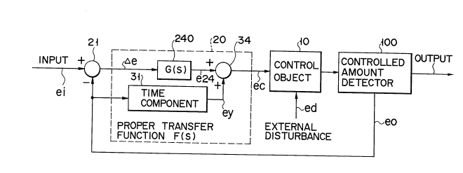
Now, referring to Fig. lA and Fig. lB, the basic
system configuration of the present invention is
described. In the system configuration of Fig. lA, the
control variable command ei is input to a subtracter
(comparator) 21. The subtracter 21 feeds a difference
~e between the controlled variable eo and the control
variable command ei to an adder 34, via a circuit 240
having a transfer function G(s). Subsequently, the
adder 34 feeds to the controlled object 10 the sum of an
output e24 of the transfer function G(s) circuit 240 and
an output ey of an delay element 31 which is available
with the controlled variable eo delayed by a given time.
It is noted that the disturbance ed of the feedback con-
trol system is added to controlled ob;ect 10 in the pre-
sent invention.
3~ ~
- 17 -
With the controlled variable output eo of the
controlled object lO negatively fed back to the
subtracter 21, and subsequently added to an output e24
after the delay by a given time, the controlled variable
eo settles within a finite time (this finite settling
mechanism is described later).
The system illustrated in Fig. lB is configured
with a minor negative feedback loop added to the
configuration in Fig. lA. Namely, the output ey of the
delay element 31 is transformed into a local feedback
signal e32 via a circuit with a transfer function H(s)
other than l. At a subtracter (comparator) 33, a
feedback signal ex is generated as a difference
between the controlled variable eo and the local feed-
back signal e32. Then, the feedback signal ex is notonly negatively fed back to the subtracter 21 but
also added to the output e24 after the delay by a given
time.
With reference to Fig. lA or Fig. lB, the transfer
function F(s) (- ~e/ec) of the control computation unit
20 is a "proper function" which refers to that the
degree sa of a complex parameter s of the denominator of
the expression which denotes the transfer function F(s)
is equal to or more than the degree sb of a numerator's
complex parameter s (sa ~ sb).
Assuming that the control computation unit 20
comprises of a proportional element P and an integration
3`8
,~'
- 18 -
element I, for example, the transfer function F(s) of
the control computation unit 20 becomes P + I/s =
(Ps + I)/s, whereby the degree (first order) of the
denominator's complex parameter s is rendered equal to
the degree (first order) of the numerator's complex
parameter s. This transfer function F(s) is assumed to
be a proper function in the specification of the present
invention.
Where the transfer function F(s) of the control
computation unit 20 is assumed as (Ps + I)/s2, with the
degree (second order) of the denominator's complex
parameter s surpassing the degree (first order) of the
numerator's complex parameter s, this transfer function
is also regarded as a proper function in this
specification.
Incidentally, to ensure finite settling in the
response to the system of Fig. lA, the transfer function
G(s) of the circuit 240 should have an element of dead
time or delay time.
Further, according to the configuration of Fig. ls,
the finite setting can be achieved even if the input ei
is applied to the subtracter 33, as is indicated by the
broken line in Fig. lB.
The present invention disclosed in this specifica-
tion is characterized in that the control computation
unit 20 is devoid of a differentiation element which is
readily affected by noises but added parallel data
J ~v o
-- 19 --
processing circuit configured using a delay element 31
to lessen the time of settling the controlled variable
eo.
The above-remarked system configurational feature
is illustrated hereunder through the introduction of
some preferred embodiments well depicting the present
invention.
(lst Preferred Embodiment)
Presented in Fig. 2 is the 1st preferred embodiment
of the present invention which is based on the system
configuration ln Fig. lB. In this embodiment, the
controlled object 10 is given by an integrator, likewise
in the preferred embodiment shown in Fig. 13, wherein
the controlled object 10 is otherwise given by an
integrator 11 and an adder 12 which is subjected to the
disturbance ed. The control computation unit 20
includes subtracters 21 and 24, an integrating amplifier
22, and a proportional amplifier 23, all of which are
the same configurational element as presented in
Fig. 13. The numeral 30 stands for a proportional
amplifier, 31 for a delay element, 32 for an integrating
amplifier, 33 for a subtracter, and 34 for an adder,
these being the elements newly added to the configura-
tion in Fig. 13.
~ difference ex between the controlled variable eo
detected by the control variable detector provided for
the controlled object 10 (omitted from being illustrated
~0~5~38
- 20 -
in the figure), and the output of an integrating
amplifier 32 is figured out by a subtracter 33. The
calculated difference ex is input not only to the
subtracter 21 but also to the proportional amplifier 23
and the delay element 31.
As specified in the figure, the delay element 31
has a transfer function [Kd (1 - E-STc)] including
another transfer function E-STC associated with a delay
(dead) time. The output ey from the delay element 31 is
of a proportional gain Kd-multiple of the difference
between an input "1" applied to the delay element, and
an input likewise applied to the delay element with a
delay Tc provided (the latter input being otherwise
defined as an input E-STC which is a past event by time
Tc). The delay time TC is selected e~ual to the time
necessary for settling the controlled variable eo.
The output ey of this delay element is input to the
integrator 32 while the control computation unit 20 has
a loop fabricated with the delay element 31 and the
integrating amplifier 32.
The control variable command ei is multiplied as
much as Ka, a proportional gain b~ the proportional
amplifier. An output e30 of this proportional amplifier
30 is input to the subtracter 21 in which the difference
~e between the output ex of the subtracter 33 and the
output e30 is figured out. Further, the dif~erence ~e
goes through integrating amplification by the integrating
2~ 3`~
- 21 -
amplifier with the integrating gain Ki. From an
output e22 of this integrating amplifier 22, e23, a
proportional gain Kp-multiple so amplified of a
differential signal ex by the proportional amplifier is
subtracted. Moreover, by an adder 34, the output ey of
the delay element 31 is added to the consequence of the
above subtraction, whereby the manipulation variable
command ec is calculated. The controlled ob;ect 10 is
operated according the manipulation variable command ec
just calculated.
Figuring out a command transfer function Gc(s), the
transfer function of the controlled variable eo to the
control variable command ei leads to establishing
expression (15) below:
Ki
Gc(s) = eo(S) = Ka s2
ei(s) Kp+Ki-Kd(1_-STC
s+Kd(
= KaKi S+Kd ( l--STC~
s(s2+Kps+Ki) ... (15)
Further calculating a disturbance transfer function
Gd(s), the transfer function of the controlled variable
eo to the disturbance ed draws expression (16) below:
20~
- 22 -
Gd(s) = eo(S) s
ed(s) Kp+Ki-Kd( 1_E-STC)
s+Kd( 1_E-STC)
5= s+Kd( 1-E-STC)
s(s2+Kps+Ki) ... (16)
Comparing expressions (15) and (16) with each other
is followed by the finding that the relationship given
by expression (17) below exists:
Gc(s) = Gd(s) .................................. (17)
The time response of the controlled variable eo to
the control variable command ei can be calculated by
being multiplied with a coefficient (KaKi), following
time-integrating the time response of the controlled
variable eo in the case where the controlled ob;ect
undergoes the disturbance ed of the same function as
that of the control computation unit. Therefore, if the
time response to the disturbance is feasible Tc time
after, the time response to the controlled variable
command remains unchanged Tc time after, whereby both
the time response to the disturbance and the time
response to the control variable command can be settled
within a finite time Tc.
Assuming that the disturbance ed(s) is a unitary
step function (l/s), a controlled variable eo(s) is
obtained according to expression (18) below:
` .~ 202533g
- 23 -
eo(S) = Gd(S) 1 5 S+Kd(l-~,-STC~
S s(s2+Kps+Ki)
+ kd(l_-STC~
s2+Kps+ki s(s2+Kps+Ki) ... (18)
Next, a time response eo(t) is figured out through
inverse Laplace transformation. Considering that
inverse Laplace transformation brings the term -STC to
0 as long as there exists the relationship 0 ~ t ~ Tc,
expression (19) is established while expression (20)
concurs with the relationship t > Tc. Namely, in the
relationship 0 ~ t ~ Tc,
-KPt
eo(t) = E 2 { - sin~t-Kdcos~t KPKidsin~t} + Kd
... (19)
where
/Éi _ Kp2
On the other hand, in the relationship t > Tc,
-KPt
(t) 2 { sin~t-Kdcos~t KPKdsin t} Kd
Ki 2Ki~ Ki
- 2 {-Kicos~(t-Tc) Pi sin~(t-Tc)} + Kd
--KPt
= 2 (asin~t + ~cos~t) ... (20)
Provided,
a = 1 _ KpKd + Kd 2 sin~Tc + KpKd 2 cosTc
~ 2Ki~ Ki 2Ki~
` ~` 2~2S~33
- 24 -
Kd + Kd~E~COS~TC + KPKdE 2 sin~Tc
Ki Ki 2Ki~
Adjusting parameters Kp, Kd, Ki, and Tc in a manner
that both the coefficient a of sin~t within the bracket
of the right side of expression (20) with respect to the
time response eo(t) and a coefficient ~ of cos~t will
become 0, results in rendering the time response eo(t)
maintainable always at 0 under the condition with the
relationship t > Tc. Namely, for a stepwise change of
the disturbance ed, the controlled variable eo exhibits,
until Tc time, the time response eo(t) given by
expression (19) which complies with the disturbance.
However, the time response conforming to the disturbance
becomes 0 after Tc time, thereby the time response can
be settled within a finite time equal to the delay time
Tc of the delay element 31.
Also, the time response of the controlled variable
eo in the case where the control variable command ei
varies following the unitary step function, gets through
with changing by the time Tc according to the relation-
ship of expression (17), and thereafter (after the
elapse of Tc time), the time response remains unchanged
with the time Tc getting fixed, whereby the time
response of the controlled variable eo can therefore be
settled within a finited time.
Figuring out how much is the value at which the
controlled variable eo get settled when the control
~ ~ 2 ~ ~ 5; 3 3 - 8 ~
- 25 -
variable command ei is added with the unitary step
function (l/s) out of the command transfer function
Gc(s) shown by expression (15), according to the final
value theorem draws expression (21) below:
lim eo(t) = lim S-KaKi{s+Kd(l--sTc)}
t~ s~0 s(s2+Kps+Ki) s
1 IKd(l-E-STC)
= lim Kaki s
s~O s2+Kps+Ki
= Ka(l+kdTc) ... (21)
Therefore, setting Ka so that it will meet the
relationship of expression (22) renders practicable to
undertake such control wherein the control variable
command and the controlled variable are made equal to
one another.
Ka = (1 + KdTc)-l ,. (22)
The range of adjusting the proportional gain Kp,
integration gain Ki, delay time Tc, and delay element's
gain Kd so that the coefficient a o sin~t and the
coefficient ~ of cos~t within the bracket of the right
side of expression (20) is limitless. Given hereunder
is one instance showing the respective values to which
Kd, Ki, and Ka are adjustable, with the time desired for
settling the controlled variable assumed as 1 second,
delay time Tc also assumed as 1 second, and proportional
gain Kp supposed as 2 identical with the proportional
2~
- 26 -
gain of sampled data control presented in Fig. 18.
With Tc = 1 second and Kp = 2 assumed.
Kd = 1.820025154
Ki = 24.8037447
Ka = (1 + KdTc)-l = 0.354606766
Fig. 3 indicates the response waveforms a variable
with the above-quoted respective gains in the lSt
preferred embodiment of the present invention. This
response waveforms refers to the waveforms respectively
lo of a control variable eo(t) and a manipulation variable
command ec(t) in the case where the control variable
command ei changes stepwise from 0 to 1 at the time
t = 0 second and the disturbance ed varies likewise from
0 to -1 at the time t = 5 seconds, wherein the time of
settling the control variable selected at 1 second equal
to the delay time Tc for the respective changes of the
control variable command ei and disturbance ed.
Fig. 4 shows the response waveforms in the case
where the controlled object -- an integrator of a unit
gain -- has had its parameter of inverse Laplace
transformation varied 25% from l/s to 1.25/s. The
conditions of measuring the response waveforms in Fig. 4
are the same as those for the measurement of the
response waveforms illustrated in Fig. 3. Compared with
the alteration in control response from Fig. 18 to
Fig. 19 in the case of finite settling control in
sampled data control, the deterioration which the 1st
2a2~8-
.--
- 27 -
embodiment pf the present invention experiences over
control response, is less with its robustness or
proofness as available in a continuous-tlme system
against parametral fluctuations remaining unchanged.
As in the foregoing, according to the preferred
embodiment of the present invention, the continuous-time
system enables to settle the control response to a
control variable command and a disturbance within a
finite time. Thus, the embodiment makes feasible to
implement the control which is characterized by such
smoothness of performance and robustness against
parametral fluctuations of the control system as
available in the continuous-time system, as well as by
such capability of finite-time settling the controlled
variable as obtainable in sampled data control.
(2nd Preferred Embodiment)
Fig. 5 shows a system configuration of the 2nd
preferred embodiment of the present invention. The 1st
preferred embodiment illustrated in Fig. 2 is an
instance of a continuous-time system while the 2nd
preferred embodiment given in Fig. 5 is another instance
of sampled data control.
The controlled ob;ect 10 in this preferred
embodiment is of such a system configuration as includes
an integrator 11 and comprises an adder 12 which suffers
the disturbance ed, in addition to the integrator. A
control computation unit 20 includes samplers 25 and 26
` ~ 2~338
- 28 -
to provide the sample data signals respectively of the
control variable command ei for sampled data control,
and the controlled variable eo, a feedback signal,
subtracters 21 and 24, an integrator 27, a proportional
amplifier 28, and a sample holder 29. The system
configuration of the 2nd preferred embodiment is
identical with that presented in Fig. 16 as an example
of sampled data control. The 2nd preferred embodiment of
the present invention has a proportional amplifier 35, a
delay element 36, an integrating amplifier 37, a
subtracter 38, and an adder 39 newly added.
A difference ex between a sample data e26 of the
controlled variable eo detected by a controlled variable
detector (omitted from being illustrated) and an output
e37 of the integrating amplifier 37 is calculated by the
subtracter 38. The calculated difference ex is input
not only to the subtracter 21 but also to the propor-
tional amplifier 28 and the delay element 36. As
illustrated in the figure, the delay element 36 keeps a
transfer function [Kd (1 - Z-n)] including a pulse
transfer function z-n which denotes a delay time (dead
time) component, the n-multiple (n: an integer) of an
sampling period T. An output ey of the delay element 36
is a proportional gain Kd-multiple of the difference
between the input corresponding to the output ey, and
the input delayed as much as a delay time nT. The delay
time nT is so selected equal to the time desired for
~8~5338
- 29 -
settling the controlled variable.
The output ey of the delay element 36 is negatively
fed back to its input via the integrating amplifier 37
and the subtracter 38, whereby, within the control
computation unit 20, a cloop comprising the delay
element 36 and the integrating amplifier 37 is formed.
The control variable command ei is multiplied as
much as Ka, the proportional gain by the proportional
amplifier 35. An output e35 of this proportional
amplifier 35 is input to the subtracter 21 wherein the
difference ~e between the output e35 and an output ex of
the subtracter 38 is figured out. Further, the figured
out difference ~e goes through integrating amplification
by the integrating amplifier 27 with an integration gain
Ki. From an output e27 of ~his integrating amplifier, a
proportional gain Kp-multiple e28 of a differential
signal ex which is provided by the proportional
amplifier 28 is subtracted by the subtracter. An output
e24 obtained through the above subtraction is added with
the output ey of the delay element 36 by the adder 39.
The outcome e39 of this addition is input to the sample
holder wherein the individual data of time-discontinuity
provided through sampled data computation are trans-
formed into a series of signals which are subsequently
output as a manipulation variable ec. The controlled
object 10 is operated according this manipulation
variable command ec.
2ff~:338
- 30 -
The above-illustrated system configuration is
alternative of the 1st preferred embodiment of the
present invention, and likewise with the 1st preferred
embodiment, adjusting a proportional gain Kp, integra-
tion gain Ki, delay time nT, and a gain Kd of the delayelement enables the 2nd preferred embodiment to
undertake finite settling control. Presented below is
one case showing the individual settings respectively of
the delay element's gains Kd, integration gain Ki, and
another parameter Ka, wherein the sampling interval T is
selected at 0.1 second, n at 10, and the proportional
gain Xp at 2 identical with that of the 1st preferred
embodiment so that the delay time nT will be 1 second,
the time within which finite settling control is
5 desired. with T = 0.1 second, n = lo, and Kp = 2,
Kd = 1.304976237
Ki = 19.28352216
Ka = (1 + Kd nT)~l = 0.4338439521
Fig. 6 shows the respective response waveforms in
the 2nd preferred embodiment wherein the parameters Kd,
Ki, and Ka are selected as specified above. These
response waveforms refer to the waveforms respectively
of the control variable eo(t) and the manipulation
variable command ec(t) in the case where the control
variable command ei changes stepwise from 0 to 1 at the
time t = 0 second, and the disturbance ed likewise alter
from 0 to -1 at the time t = 5 seconds. In this case,
~ 0~3
.
- 31 -
for some change of the control variable command ei,
finite settling control is effected within a time of
0.9 second equal to the sum of 9 sampling intervals,
each sampling interval being ((n - l)T), and for a
certain change of the disturbance ed, finite settling
control is implemented within a time of 1 second equal
to the sum of 10 sampling intervals, each sampling
interval being (nT).
Given in Fig. 7 are the response waveforms in the
case where the controlled ob~ect -- an integrator of a
unit gain -- has had its parameters of inverse Laplace
transformation varied 25% from 1/2 to 1.25/s. The
conditions of measuring the response waveforms in Fig. 7
are the same as those for the measurement of the
response waveforms illustrated in Fig. 6. Referring to
these response waveforms, it is witnessed that they
exhibit the propensity almost identical with that
observed in the 1st preferred embodiment.
As described above, according to the 2nd preferred
embodiment of the present invention, it is practicable
to implement control characterized by smoothness of
performance, and such robustness as available in
continuous-time system against parametral fluctuations
of the control system while settling the response
respectively to a certain change of the control variable
command and some alteration of the disturbance within a
finite time.
~02533
r
- 32 -
(3rd Preferred Embodiment)
Fig. 8 illustrates the system configuration of the
3rd embodiment if the present invention. The controlled
object 10 given in each of the 1st and 2nd preferred
embodiments is of such a configuration that the system
is represented by the integrator 11 only whereas the
controlled object 10 in the 3rd preferred embodiment
comprises a first order lag element 13 and the integrator
11. The controlled ob;ect 10 quoted in the 3rd
preferred embodiment corresponds to such a system
including a motor current control minor loop for motor
speed control, wherein motor current control is
implemented with the first order lag, following the
manipulation variable command. The numeral 10 denotes a
controlled object which comprises an integrator 11, an
adder 12 which incurs the disturbance ed, and the 1st
order lag element 13. The cutoff angular frequency is
GdCC .
Included in a control computation unit 20 are
subtracters 21, 24, and 33, an adder 34, integrating
amplifiers 22 and 32, proportional amplifiers, and a
delay element 31. This system configuration is the same
as that of the 1st preferred embodiment. The numeral 40
stands for a proportional amplifier, 41 for and adder,
and 42 for a first order lag element, all of which are
newly added to the configuration of the 1st preferred
embodiment to make up the 3rd preferred embodiment.
` ~ 2~2~33;~
- 33 -
The difference between the controlled variable eo
detected by a control variable detector (omitted from
being illustrated) and an output e32 of the integrating
amplifier 32 is figured out by a subtracter 33. The
difference ex is input not only to the subtracter 21 but
also to the proportional amplifier 23, and delay element
31.
The delay element 31 keeps a delay (dead) time
transfer function -STC included transfer function
[Kd (1 _ ~-STc)]r as shown in the figure. The output ey
of the delay element 31 is a proportional gain
Kd-multiple of the difference an input corresponding to
the output ey and another input delayed as much as a
delay time Tc. The delay time Tc is selected equal to
the time within which the controlled variable of the
system is desired to be settled.
The output ey of the delay element 31 is input to
the integrating amplifier 32 through a first order lag
element 42 with adjustment as far approximation as
possible to the adjustment of the first order lag element
13 contained in the controlled ob;ect 10. Within the
control computation unit 20, a loop is fabricated with
the delay element, first order lag element 42, and
integrating amplifier 32.
The control variable command ei is multiplied as
much as Ka, a proportional gain by the proportional
amplifier. The output e30 of this proportional
2~53`~
. ~
- 34 -
amplifier 30 is input to the subtracter 21, wherein the
difference ~e between the output e30 and the output ex
of the subtracter 33 is calculated. Further, the
difference ~e experiences integrating amplification by
the integrating amplifier 22 with the integrating gain
Ki.
The output 30 of the proportional amplifier 30 is
also input to the proportional amplifier 40 wherein the
output is multiplied as much as Kb, a proportional gain.
The output e22 of the integrating amplifier 22 and the
output e40 of the proportional amplifier 40 are summed
up by the adder 41. From this sum-up signal of the
adder 41, a proportional gain Kp-multiple e23 which the
proportional amplifier 23 provides of a differential
signal ex, is subtracted by the subtracter 24. Further,
the output ey of the delay element 31 is added to the
output e24 of the subtracter 24 by the adder 34, whereby
the the manipulation variable command ec is figured out.
The controlled object 10 is operated according to the
manipulation variable command ec just calculated above.
Though a detailed description is refrained here, it
is clear that, even with the above-remarked system
configuration wherein the controlled ob;ect 10 is
represented by the first order lay element 13 and the
integrator 11, finite settling control is feasible
similarly to the case in which the controlled ob;ect ls
denoted only by an integrator.
2~2~3~8
- 35 -
Fig. 9 shows the response waveforms confirmed in
the 3rd preferred embodiment. These response waveforms
are obtained when the first order lag element 42 of the
control computation unit 20 has its cutoff angular
frequency ~cc* adjusted equal to ~cc, with the cutoff
angular frequency ~cc of the first order lag element of
the controlled object 10 set to 10 rad/s. Further, the
response waveforms in Fig. 9 refers to those
respectively of the controlled variable eo(t) and the
lo manipulation variable command ec(t) in the case where
the control variable command ei carries stepwise from 0
to 1 at the time t = 0 second, and the disturbance ed
likewise changes from 0 to -1. These response waveforms
signify that finite settling control is completed for a
period of 1 second, equal to the delay time Tc, for the
respective variations of the control variable command ei
and the disturbance ed.
Likewise in the 2nd preferred embodiment specified
in Fig. 5, the 3rd preferred embodiment in Fig. 8 can be
modified for use in sampled data control.
(4th Preferred Embodiment)
Illustrated in Fig. 10 is a system configuration of
the 4th preferred embodiment of the present invention.
Commonly in the 1st and 2nd preferred embodiments, each
controlled object 10 is of such a configuration wherein
the controlled object is represented by the integrator
11 only, whereas in the 4th preferred embodiment, the
~ ~ 2~5338
- 36 -
controlled ob;ect 10 is defined by a dead time element
14 and the integrator 11 which are serially connected to
each other. The controlled ob;ect 10 corresponds to a
water tank undergoing water level control wherein a flow
control valve has some dead time in its response to the
changes of the controlled variable.
The numeral 10 signifies a controlled object which
is represented by an integrator 11, an adder 12 which
incurs the disturbance ed, and a dead time element 14.
The dead time of the dead time element 14 is Td.
Included in a control computation unit 20 are
subtracters 21, 24, and 33, an adder 34, integrating
amplifiers 22 and 23, proportional amplifiers 23 and 30,
and a delay element 31. This system configuration is
the same as that of the 1st embodiment presented in
Fig. 2; provided, the delay time of the delay element 31
is different from that of the counterpart in the 1st
preferred embodiment. The numeral 43 denotes an
integrating amplifier, 44 a proportional amplifier, 45
an adder, 46 and 47 delay elements, and 48 an adder, all
of which are newly added to the configuration of the 1st
preferred embodiment.
The difference ex between the controlled variable
detected by a control variable detector (omitted from
being illustrated) and an output e32 of the integrating
amplifier 32 is figured out by the subtracter 33. The
calculated difference ex is then input not only to the
2~2~33~
- 37 -
subtracter 21 but also to the proportional amplifier 23,
and delay elements 31 and 46.
As shown in the figure, the delay element 31 keeps
a transfer function (1 _ -STd*) including the transfer
function ~-STd* of the delay time (dead time) adjusted
as far approximation as possible to the delay time Td of
the controlled object 10. The output e31 of the delay
element 31 is a difference between the input applied
thereto and another input also fed thereto while delayed
by Td.
The output e31 of the delay element 31 is
integrated by the integrating amplifier 43 with the same
integration gain Ki as that of the integrating amplifier
22, and subsequently, proportionally amplified as much
as Kp, the same gain of the proportional amplifier. The
output e43 of the integrating amplifier 43, and the
output e44 from the proportional amplifier 44 are summed
up by the adder 45, whereby a sumup signal ez is
generated.
In the meantime, as shown in the figure, keeps the
transfer function [Kc ~-S(Tc - Td*)] including a delay
(dead) time transfer function ~-S(Tc - Td*). The output
ey of the delay element 46 is a proportional gain
-Kc-multiple of the differential signal ex, and input to
the delay element 46 and which is delayed by Tc - Td*.
The time Tc is so selected to settle the controlled
variable of the controlled object involved within said
3 3 ~
- 38 -
time.
The output ey of the delay element 46 is input
further to the delay element 47. As shown in the
figure, the delay element 47 keeps a delay (dead) time
transfer function ~-STd* while the output ey of the
delay element 46 delayed as much as Td*. Summing up the
outputs respectively of the delay elements 46 and 47
provides and output e47 which is proportional to the
magnitude of the signal ex delayed as much as the delay
time Tc.
The sum e48 between the sumup signal ez and the
output e47 is figured out by the adder 48, and
subsequently, input to the integrating amplifier 32.
The control computation unit 20 has a loop formed
therein with the delay element 31, integrating
amplifier, proportional amplifier, delay elements 46,
and 47, and the integrating amplifier 32.
The control variable command ei is multiplied as
much as Ka, a proportional gain by the proportional
amplifier 30. The output e30 of this proportional
amplifier 30 is input to the subtracter 21 wherein the
difference ~e between the output e30 and the output ex
of the subtracter 33 is calculated. The figured-out
difference ~e goes through integrating amplification
thereafter by the integrating amplifier 22. From the
output e22 and the output e23, a proportional gain Kp-
multiple of a differential signal ex, and which is from
2025338
- 39 -
the proportional amplifier 23 is subtracted by the
subtracter 24. The outcome e24 of this subtraction and
the output ey of the delay element 46 are summed up by
the adder 3g whereby the manipulation variable command
ec is provided. The controlled object 10 is operated
according to the manipulation variable command ec just
calculated.
With the system configuration referred to above,
finite settling control is feasible even where a
controlled ob;ect contains a dead time element. Fig. 11
gives the response waveforms which go with the 4th
preferred embodiment. More precisely, they are
obtainable where the dead time Td of the dead time
element of the controlled object 10 is set to 0.1
second, with the dead time Td* of the respective dead
time elements 31, 46, and 47 within the control
computation unit 20 adjusted equal to Td. Namely, these
response waveforms refer to the waveforms respectively
of the controlled variable eo(t) and the manipulation
variable command ec(t) in the case where the control
variable command ei changes stepwise from 0 to 1 over
the time T = 0 second, and the disturbance ed likewise
varies from 0 to -1 at the time T - 5 seconds. Further,
they signify that for some change of the control
variable command ei, the controlled variable eo is
settled over a time of 1.2 second equal to Tc + Td
while, for a certain variation of the disturbance ed,
~ ~ 20~3~
- 40 -
the controlled variable eo gets settled over a time of 1
second e~ual to the delay time Tc.
In the 4th preferred embodiment shown in Fig. 10,
the controlled object 10 contains some dead time. Even
where the control computation unit 20 involves certain
computational delay time and/or even when the control
variable detector (omitted from being illustrated)
includes some delay time in its detection, adjusting the
Td* included in the dead time element of the control
computation unit 20 as far approximation to the sum of
the above-remarked dead time and the respective delay
times as possible enables finite settling control
similar to the 1st through 4th preferred embodiments.
Further with reference to Fig. 10, even when the
dead time element 14 of the controlled ob;ect 10 is
regarded existing as a computational delay time of the
control computation unit 20, the computational delay
time is negligible in the consideration of an entire
control system. With this in view, it is clear that
similar finite settling control is practicable
regardless of the dead time of the controlled object 10.
In case the control variable detector (omitted from
being illustrated) involves some detection delay time,
the control system is of such a configuration with the
dead time element 14 of the controlled object 10 shifted
between the output of the integrator 11 and the
integrator 33 of the control computation unit 20. This
~ 2Qi2~`3~
- 41 -
control system may be considered basically identical
with the control system shown in Fig. 10. Therefore,
with the control system wherein the control variable
detector has some delay time in its detection, similar
finite settling control is possible.
Fig. 12 presents the response waveforms which are
out with the embodiment wherein the same control
computation unit as that incorporated in the 4th
preferred embodiment is applied, with the detection
del'ay time Td of the control variable detector (omitted
from being illustrated) set to 0.1 second, and further
with the controlled ob~ect 10 configured such as is
represented the integrator 11 only. These response
waveforms refer to those respectively of the controlled
variable eo(t) and the manipulation variable command
ec(t) in the case the control variable command ei
changes stepwise from 0 to 1 at the time t = 0 second,
and the disturbance ed likewise varies from 0 to -1.
Also in this case, for some changes respectively of the
control variable command ei and the disturbance ed, each
eo(t) of the corresponding controlled variables is
settled over a time of 1 second equal to Tc. The
response waveforms in Fig. 12 are different from those
in Fig. 11 at one point that, with the former, there
goes a 0.1 second quicker response to each control
variable command, as compared with the latter.
Therefore, even where there coexist some
` ~ 202~338
- 42 -
computation delay time, dead time of a controlled
object, and detection delay time of the control variable
detector, adjusting the delay times Tc and the dead time
Td*, with the time desired for due settling and the
computation delay time as well as the detection delay
time combined together renders the same control
computation unit 20 applicable. In addition, similarly
to the 2nd preferred embodiment, the 4th preferred
embodiment is allowed to apply for sampled data control.
It is noted that each o~ the above-remarked
proportional amplifiers, integrating amplifiers, first
order lag elements, adders subtracters, and so forth is
easily realized with an operational amplifier, a
microcomputer or similar means thus far used with the
feedback control system. For the delay element touched
upon above, a coaxial cable which uses an electrical
propagation delay characteristic, is applicable as a
substitute, so far as a continuous-time system is
concerned. On the other hand, in sampled data control,
the delay element can otherwise be materied, using a
shift register or a memory.
So far, some preferred embodiments of the present
invention have been illustrated in this specification.
For some other controlled objects, the present invention
further enables similar finite settling controls, and
for one controlled object, the present invention also
undertake finite settling control in various system
- ~. 2~533~
- 43 -
configurations other than those illustrated in the
above-quoted preferred embodiments.
As described above, the present invention wherein a
control computation unit of the feedback control system
is added with a delay element as one system component
primarily for prescribing the time desired for due
settling, enables finite settling control so far
considered workable only in sampled data control,
likewise in a continuous-time system. According to the
present invention, it is theoretically feasible to make
an infinite time necessary for due settling finite, and
in a practical sense, a finite settling time may be
remarkably shortened.
Applying the present invention for sampled data
control renders practical to realize control for due
settling within a certain duration equivalent to an
optional plurality of sampling periods, and further
achieve robust control characterized by not only
smoothness of performance -- a feature of a continuous-
time system -- assured even with finite settling control
but also hardness of being sub;ect to adverse effects by
noises and proofness against parametral fluctuations.
Thus, the present invention is applicable for a wide
variety of controllers with feedback control speciality,
with immense serviceability expected.
The following literature discloses the fundamentals
of the present invention:
~ 202~3~8
- 44 -
Otto J. M. Smith, "Feedback Control Systems",
McGraw-Hill Book Co., Inc., 1958, pp 341 - 345.
All disclosures in the above literature are
incorporated in this specification.
In Fig. 10 - 29(e) on page 342 of the above
literature, there is presented a system configuration
similar to those shown in the preferred embodiments of
the present invention. Although the system
configuration of the present invention has a resemblance
to the system configuration of said literature, it is
different from the present invention.
More specifically, the block P in Fig. 10 - 29(e)
of the literature corresponds to the time element 31
given in this specification. But this block includes a
differentiating element, thereby undergoing adverse
effects by noises with almost no practical
serviceability made available.
Further, the system configuration in the above
literature requires the respective inverse transfer
functions (l/Gl, l/G2, and l/F) for the transfer
functions Gl, G2, and F, while the control computation
unit 20 in each of the preferred embodiments in this
specification require no such an inverse transfer
function.