Language selection

Search

Patent 2025404 Summary

Third-party information liability

Some of the information on this Web page has been provided by external sources. The Government of Canada is not responsible for the accuracy, reliability or currency of the information supplied by external sources. Users wishing to rely upon this information should consult directly with the source of the information. Content provided by external sources is not subject to official languages, privacy and accessibility requirements.

Claims and Abstract availability

Any discrepancies in the text and image of the Claims and Abstract are due to differing posting times. Text of the Claims and Abstract are posted:

  • At the time the application is open to public inspection;
  • At the time of issue of the patent (grant).
(12) Patent: (11) CA 2025404
(54) English Title: TAMPER EVIDENT CONTAINER
(54) French Title: CONTENANT ANTI-VIOL
Status: Term Expired - Post Grant Beyond Limit
Bibliographic Data
Abstracts

English Abstract


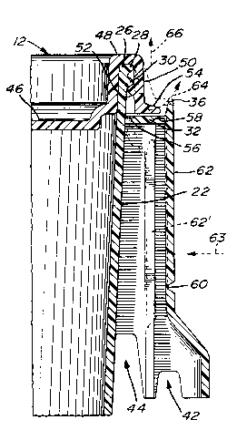
The disclosure herein describes a container
adapted to securely engage a cover displaying a
peripheral depending skirt; it comprises a body with side
walls having an upper edge portion adapted to engage the
skirt of the closure. The side walls include a
peripheral inverted L-shaped flange. Integrally formed
with the flange is a pair of handles each including a
frangible tab which must be broken to remove the cover
from the container; however, the broken tabs do not
hinder the reclosure of the container, nor the handling
of the container. The handles are so shaped as to allow
similarly constructed containers to be nested one into
the other.


French Abstract

La présente invention porte sur un récipient adapté pour se mettre en prise sur un couvercle comportant une jupette périphérique; il est constitué d'un corps dont les parois latérales ont un bord supérieur adapté pour se mettre en prise sur la jupette du couvercle. Les parois latérales comportent un rebord en L inversé sur leur périphérie. Le rebord comporte une paire de poignées intégrées comprenant chacune une languette frangible qu'il faut briser pour retirer le couvercle du récipient; les languettes brisées n'entravent cependant pas la fermeture subséquente du récipient, non plus que sa manutention. Les poignées ont une forme permettant d'emboîter l'un dans l'autre les récipients de construction similaire.

Claims

Note: Claims are shown in the official language in which they were submitted.


1. A container adapted to securely engage a
cover displaying a peripheral depending skirt,
comprising:
- a body including side walls having an
upper edge portion adapted to engage the peripheral
depending skirt of a cover; said side walls including a
peripheral flange consisting of a horizontal portion
projecting outwardly from said side wall and of an outer
vertical portion distanced from said side wall, said
portions receiving in close relationship therewithin a
lower part of said skirt; and
- tab means having a horizontal portion
integrally formed with said side wall and with said
horizontal portion of said flange and a downwardly
extending vertical portion integrally formed with said
vertical portion of said flange; said horizontal and
vertical portions of said tab means being connected to
said horizontal and vertical portions of said flange
through weakened areas to thereby render said tab means
breakable when pressure is applied thereon thus providing
visual indication of tampering, whether authorized or
unauthorized, and allowing removal of the cover from the
container;
- wherein said vertical portion of said
flange includes an enlarged area defining a handle for
said container; said tab means being provided in said
enlarged area.

2. A container as defined in claim 1, wherein
said container defines four slightly inclined walls, said
handle being provided on each of two opposite side walls
of said container.
3. A container as defined in claim 1 or 2,
wherein said weakened areas are reduced thicknesses in
the material of said body and define a U-shaped outline
in said enlarged area.
4. A container as defined in claim 1 or 2,
wherein said enlarged area includes an outwardly
projecting lower portion displaying recessed areas along
lower edges thereof; said recessed areas including an
outer recessed area in vertical alignment with said outer
vertical portion of said flange to thereby receive
therein an upper portion of the outer vertical portion of
a flange of a lower similarly constructed container
nested in said container.
5. A container as defined in claim 4, wherein
said recessed areas include an inner recessed area in
vertical alignment with the upper edge portion of the
side wall of the container to thereby receive therein the
upper edge portion of the side wall of a similarly
constructed container nested in said container.
6. A container as defined in claim 5, wherein
the upper edge portion of said container contains

external circumferential bead means adapted to be
securely engaged with internal circumferential bead means
on the skirt of said cover.
7. A container as defined in claim 1, wherein
said container is formed of an injection-moulded plastic
material.

Description

Note: Descriptions are shown in the official language in which they were submitted.


2 ~ ?~
FIELD OF THE INVENTION
The invention relates to a container adapted to
securely engage a cover and equipped with frangible tabs,
the breaking of which will indicate that the closed
container has been tampered with and, also, will allow
the cover to be easily lifted from the container.
R~ ~q~uND OF THE INVENTION
Containers having a tamper-proof feature have
become an important item of commerce. Generally, these
tamper-proof assemblies comprise a cover with a tab
attached to one part of the assembly by a breakable web.
Often, the tab is broken simply by the act of opening the
container, i.e. removing the cover. One such assembly
may be found described in U.S. patent No. 4,362,253
issued December 7, 1982 to Wortley et al.
ORJECTg AND gTATEMENT OF THE lNv~ lON
It is an object of the present invention to
provide, on a container which is adapted to securely
engage a cover, an integrally formed side wall flange
including frangible tab means which must be broken in
order to have access to the cover's peripheral edge in
order to remove or lift the cover from the container.
A close relationship is defined between the
flange and the depending skirt of the cover thus

2 0 ~
~_ - 2 -
rendering difficult the insertion of fingers or prying
tools between the skirt and the flange for lifting the
cover from the container. Authorized removal of the
cover from the container is accomplished by breaking the
tab means on the flange to subsequently facilitate the
manual grasping of the skirt's lower edge and
subsequently disengage the cover from the container.
The present invention therefore relates to a
container adapted to securely engage a cover displaying
a peripheral dependent skirt which comprises:
- a body including side walls having an
upper edge portion adapted to engage
the peripheral depending skirt of the
cover; the side walls include a
peripheral flange consisting of a
horizontal portion projecting outwardly
from the side wall and of an outer
vertical portion distanced from the
side wall; these portions receive in
close relationship therewithin a lower
part of the skirt; and
- tab means having a horizontal portion
integrally formed with the side wall
and with the horizontal portion of the
flange, and a downwardly extending
vertical portion integrally formed with
the vertical portion of the flange; the

2 ~ 2 ~
~_ - 3
horizontal and vertical portions of the
tab means are connected to the
horizontal and vertical portions of the
flange through weakened areas to
thereby render the tab means breakable
when pressure is applied thereon, thus
providing visual indication of
tampering, whether authorized or
unauthorized, and allowing removal of
the cover from the container.
In one form of the invention, the tab means are
part of handles integrally formed with the container.
In another form of the invention, the handles
are constructed in a manner that similarly constructed
containers can be nested one into the other. The lower
edges of the handles are thus shaped with recessed areas
to respectively receive the flange and the upper portion
of the container wall.
Other objects and further scope of
applicability of the present invention will become
apparent from the detailed description given hereinafter.
It should be understood, however, that this detailed
description, while indicating preferred embodiments of
the invention, is given by way of illustration only,
since various changes and modifications within the spirit

_ - 4 -
and scope of the invention will become apparent to those
skilled in the art.
BRIEF DESCRIPTION OF THE DRAWINGS
Figure 1 is a top plan view of a container made
in accordance with the present invention showing part of
a cover thereon;
Figure 2 is a cross-sectional view taken along
lines 2-2 of figure 1;
Figure 3 is a cross-sectional view taken along
lines 3-3 of figure 1;
Figure 4 is a perspective view showing one
corner area of the container of the present invention;
Figure 5 is a side elevational view showing the
upper part of the container with the partly broken-away
cover thereon; and
Figure 6 is a partial cross-sectional view of
similarly constructed containers made in accordance with
the present invention in a nested engagement.
DE8CRIPTION OF PREFERRED EMBODIMENTS
Referring to figure 1, there is shown a
container, generally denoted 10, adapted to securely
engage a cover, generally denoted 12. The container has
a bottom wall 14 and four slightly inclined side walls
16, 18, 20 and 22. The four side walls display a
continuous peripheral flange, generally denoted 24,
having an inverted L-shape and disposed slightly lower

2~ 25404 z
than the upper edge portion 26 of the side wall. The
flange i8 integrally formed with the side walls and
includes peripherally spaced triangular shaped
reinforcing ribs 27 ther~hen~Ath. As illustrated in
S figure 2, the peripheral upper edge portion 26 of the
side walls display a pair of vertically spaced
circumferential bead~ 28 and 30.
Referring to figures 2, 3 and 4, the peripheral
flange 24 consists of a horizontal portion 32 having one
end integral with the side wall of the container and the
opposite end terminating in a vertical portion 34
displaying an upper extension 36 and a lower extension
38.
On two opposite sides of the container, the
flange 24 has downwardly exten~ing enlarged areas 38'
defining handles. As can be seen in figure 4, these
handles have a general rectangular shape with a
f~ol.~ardly projecting lower portion 40, the lower edge
of which displays, on the opposite narrow sides thereof,
a pair of rececse~ areas 42 and 44, the function of which
will be described hereinbelow. The outer reces~e~ area
42 is in vertical alignment with the upper portion 36 of
the flange while the inner re~ e~ area 44 is in
vertical alignment with the upper edge portion 26 of the
container.

~_ - 6 - ~ 0 2 5 4 ~ 4
As shown in figures 1 and 2, the cover 12 has
a flat central surface 46 and an inverted U-shaped
peripheral edge 48 displaying a depending skirt 50 having
a circumferential inner bead 52 and a flat outwardly
projecting lower edge 54. This lower edge is confined
within the recessed area defined by the upper edge
portion 26, the horizontal portion 32 of the flange and
the upper vertical extension 36. The material of the
cover is preferably an injection moulded plastic so that
the skirt 50 may be somewhat flexed to be forced into
snap engagement with the peripheral upper edge portion 26
of the container with bead 52 engaging underneath bead
30.
In the handle area of the flange, the
horizontal portion has a first line of reduced thickness,
such as illustrated at 56, in order to make the material
frangible along that line (horizontal portion 32 has also
a further line 58 of reduced thickness to render the
material bendable). Similarly, the front face of the
handle has a U-shaped outline 60 of reduced thickness,
thus defining a tab 62 (see figure 4).
As illustrated in figure 2, to remove the cover
securely engaged with the container, one must press on
the tab 62 in the direction of arrow 63 to force it
inwardly within the cavity defined behind the handle, as
shown by dotted lines 62'. In this position, the lower
,~. .J'

-- 7
edge 54 of the cover skirt may be manually grasped to be
lifted in the direction of arrow 64 to remove the cover,
as illustrated by arrow 66.
It is recognized that it may be possible to
insert a prying tool between edge 54 and the flange (on
side wall 20 for example) to remove carefully the cover
without breaking the tabs. However, this is extremely
difficult due to the close confinement of the skirt edge
54 rearwardly of the flange's upper portion 36.
Referring to figure 6, two similarly
constructed containers made in accordance with the
present invention are shown to illustrate the function of
recesses 42 and 44 which are adapted to respectively
receive the upper portion 36 of the flange and the upper
portion 26 of the container's side wall. Hence, nested
containers are supported by the two handles 38' on the
opposite sides of the container, and not on the inner
faces of the side walls of the container.
Preferably, the container of the present
invention is made of an injection moulded plastic
material.
Although the invention has been described above
with respect with one specific form, it will be evident
to a person skilled in the art that it may be modified

- 8 - ~ J~
and refined in various ways. For example, the lines of
reduced thickness may be formed of a series of aligned
openings or gaps thus providing the same frangible effect
to the tabs. It is therefore wished to have it
understood that the present invention should not be
limited in scope, except by the terms of the following
claims.

Representative Drawing
A single figure which represents the drawing illustrating the invention.
Administrative Status

2024-08-01:As part of the Next Generation Patents (NGP) transition, the Canadian Patents Database (CPD) now contains a more detailed Event History, which replicates the Event Log of our new back-office solution.

Please note that "Inactive:" events refers to events no longer in use in our new back-office solution.

For a clearer understanding of the status of the application/patent presented on this page, the site Disclaimer , as well as the definitions for Patent , Event History , Maintenance Fee  and Payment History  should be consulted.

Event History

Description Date
Inactive: Expired (new Act pat) 2010-09-19
Grant by Issuance 1998-09-29
Pre-grant 1998-05-19
Inactive: Final fee received 1998-05-19
Notice of Allowance is Issued 1997-11-28
Letter Sent 1997-11-28
Notice of Allowance is Issued 1997-11-28
Inactive: Status info is complete as of Log entry date 1997-11-24
Inactive: Application prosecuted on TS as of Log entry date 1997-11-24
Inactive: IPC assigned 1997-11-14
Inactive: IPC removed 1997-11-14
Inactive: First IPC assigned 1997-11-14
Inactive: Approved for allowance (AFA) 1997-11-12
Request for Examination Requirements Determined Compliant 1994-04-13
All Requirements for Examination Determined Compliant 1994-04-13
Application Published (Open to Public Inspection) 1992-03-20

Abandonment History

There is no abandonment history.

Maintenance Fee

The last payment was received on 1998-09-10

Note : If the full payment has not been received on or before the date indicated, a further fee may be required which may be one of the following

  • the reinstatement fee;
  • the late payment fee; or
  • additional fee to reverse deemed expiry.

Please refer to the CIPO Patent Fees web page to see all current fee amounts.

Fee History

Fee Type Anniversary Year Due Date Paid Date
MF (application, 7th anniv.) - standard 07 1997-09-19 1997-09-04
Final fee - standard 1998-05-19
MF (application, 8th anniv.) - standard 08 1998-09-21 1998-09-10
MF (patent, 9th anniv.) - standard 1999-09-20 1999-08-17
MF (patent, 10th anniv.) - standard 2000-09-19 2000-07-25
MF (patent, 11th anniv.) - standard 2001-09-19 2001-07-25
MF (patent, 12th anniv.) - standard 2002-09-19 2002-08-09
MF (patent, 13th anniv.) - standard 2003-09-19 2003-08-04
MF (patent, 14th anniv.) - standard 2004-09-20 2004-08-23
MF (patent, 15th anniv.) - standard 2005-09-19 2005-09-19
MF (patent, 16th anniv.) - standard 2006-09-19 2006-08-03
MF (patent, 17th anniv.) - standard 2007-09-19 2007-09-13
MF (patent, 18th anniv.) - standard 2008-09-19 2008-09-15
MF (patent, 19th anniv.) - standard 2009-09-21 2009-08-05
Owners on Record

Note: Records showing the ownership history in alphabetical order.

Current Owners on Record
IPL INC.
Past Owners on Record
MARIO GAUDREAULT
Past Owners that do not appear in the "Owners on Record" listing will appear in other documentation within the application.
Documents

To view selected files, please enter reCAPTCHA code :


To view images, click a link in the Document Description column. To download the documents, select one or more checkboxes in the first column and then click the "Download Selected in PDF format (Zip Archive)" or the "Download Selected as Single PDF" button.

List of published and non-published patent-specific documents on the CPD .

If you have any difficulty accessing content, you can call the Client Service Centre at 1-866-997-1936 or send them an e-mail at CIPO Client Service Centre.


Document
Description 
Date
(yyyy-mm-dd) 
Number of pages   Size of Image (KB) 
Abstract 1994-03-02 1 22
Cover Page 1994-03-02 1 14
Description 1994-03-02 8 236
Drawings 1994-03-02 3 123
Claims 1994-03-02 3 78
Cover Page 1993-11-02 1 14
Abstract 1993-11-02 1 22
Claims 1993-11-02 3 78
Drawings 1993-11-02 3 123
Description 1993-11-02 8 236
Description 1997-10-22 8 237
Drawings 1997-10-22 3 122
Claims 1997-10-22 3 72
Cover Page 1998-09-02 1 48
Representative drawing 1998-09-02 1 12
Representative drawing 1999-06-30 1 19
Commissioner's Notice - Application Found Allowable 1997-11-28 1 165
Fees 2003-08-04 1 34
Fees 1998-09-10 1 42
Correspondence 1998-05-19 1 37
Fees 2002-08-09 1 35
Fees 2001-07-25 1 37
Fees 1997-09-04 1 44
Fees 1999-08-17 1 43
Fees 2000-07-25 1 37
Fees 2004-08-23 1 31
Fees 2005-09-19 1 32
Fees 2006-08-03 1 43
Fees 2007-09-13 1 42
Fees 2008-09-15 1 43
Fees 1996-08-14 1 39
Fees 1995-07-11 1 39
Fees 1994-07-15 1 31
Fees 1993-09-16 1 29
Fees 1992-09-04 1 25
Courtesy - Office Letter 1994-06-01 1 54
Prosecution correspondence 1994-04-13 1 32
Examiner Requisition 1997-04-24 3 136
Prosecution correspondence 1997-10-07 2 40
Prosecution correspondence 1994-08-25 2 60
Examiner Requisition 1994-07-28 2 98
Prosecution correspondence 1994-06-29 1 29
Prosecution correspondence 1994-04-19 2 54