Note: Descriptions are shown in the official language in which they were submitted.
2~3
CONS~ANT CU~RENT VACUUM REGULATOR
Background and Summary of the Invention
The present invention relates to proportional solenoid
valves and in particular to a vacuum regulator that is
particularly adapted for use on automotive vehicles of the type
having a computer-controlled exhaust gas recirculation system.
Present day emission equipment on automobiles includes an
exhaust gas recirculation, or EGR, system which returns a portion
of the exhaust gases to the intake system of the engine. The
amount of exhaust gases introduced into the intake system is
controlled by a vacuum-actuated EGR valve. The EGR valve is
connected between the engine exhaust system and the intake
system. The degree of opening of the EGR valve and hence the
amount of exhaust gases that are introduced into the intake
system is determined by the vacuum signal supplied to the ~GR
valve. The vacuum signal is regulated by an electrically
controlled vacuum regulator valve which is in turn controlled by
the engine management computer. In particular, the vacuum
regulator is adapted to control the amount of vacuum provided to
the ~GR valve in accordance ~ith the electrical signal supplied
to the regulator by the engine control computer.
Because the vacuum regulator valve is a proportional device,
it is important that the regulator be precisely calibrated so
that a specified current signal from the engine control computer
results in a predetermined amount of negative vacuum pressure
being supplied to the EGR valve. Heretofore, vacuum regulators
- 1 -
- ` ~. ' '
.
of this type have been calibrated after assembly by energizing
the solenoid coil of the regulator with a preselected current
signal and adjusting the dimension of the working or primary air
gap between the pole piece and the armature until a predetermined
vacuum output is achieved. Thereafter, the position of -the pole
piece and/or the armature is fixed to secure the calibration. A
vacuum regulator of this type is disclosed in U.S. Patent No.
4,567,910 to Slavin et al. and assigned to the assignee of the
present invention.
The primary disadvantage of this approach is the highly
sensitive nature of the calibration process and the resulting
degree of variation in the output of the vacuum regulator to
extremely small variations in the actual dimension of the working
air gap. Moreover, because of the extremely sensitive nature of
the known calibration techniques, it is necessary to perform the
calibration adjustment very slowly to avoid overshooting the
desired set point. Consequently, the required production time
and hence the associate production cost of each unit produced in
this manner is increased. In addition, due to such factors as
component resiliency, it can be extremely difficult to precisely
hold the desired set calibration point, thereby resulting in a
unit that produces a different output than that observed when the
unit was calibrated.
Accordingly, it i5 the primary object of the present
invention to overcome the disadvantages of the prior art and
provide an improved vacuum regulator having a less sensitive
means of calibration. In particular, the vacuum regulator
,, `
, .
.
.
~7~
according to the present invention is calibrated by adjusting the
dimension of a secondary air gap provided in the flux path of the
solenoid. Because dimensional variations in thP secondary air
yap of the solenoid have a less dramatic impact on the operation
of the solenoid than dimensional variations in the primary air
gap between the pole piece and armature, the sensitivity of the
present calibration process is substantially reduced.
In general, this is accomplished by providing a vacuum
regulator with a solenoid structure having an adjustable
secondary air gap in the flux path of the solenoid at the
opposite end of the pole piece from the armature. This allows
the primary air gap at the armature end of the pole piece to be
set consistently from piece to piece thereby ;n; ;zing
variations in both the magnetic forces on the armature and in the
air ~low path through the pole piece and across the face of the
armature. Moreover, the secondary air gap provided in the
preferred embodiment of th~ vacuum regulator according to the
present invention is designed to divide the flux path of the
solenoid so that a portion of the magnetic flux crosses a
nonadjustable air gap and the remainder of the flux crosses the
adjustable air gap. In this manner, the sensitivity of the
calibration process is further reduced, thereby enabling more
accurate settings with less chance of overshooting the desired
set point. Consequently, the rate of production of vacuum
regulators according to the present invention is improved.
Additional objects and advantages of the present invention
will become apparent from a reading of the following detailed
2 ~ t~
description of the preferred embodiment which makes reference to
the accompanying drawings in which:
Brief Description of the Drawings
Figure 1 is a section view of a vacuum regulatsr according
to the present invention;
Figure 2 is an enlarged view of the primary air gap portion
of the vacuum regulator of Figure l;
Figures 3a - 3b are top and side plan YieWs, respectively,
of the L-frame flux collector member of the solenoid;
Figure 4 is a plan view of the flux collector ring of the
solenoid;
Figure 5 is a view of the pole piece of the solenoid with
half in section and half in elevation.
Figure 6 is a view of the valve seat member of the solenoid
with half in section and half in elevation;
Figure 7 is a view of the calibration screw and calibration
flux collector subassembly of the solenoid with half in section
and half in elevation;
Figure 8 is a plan view of the armature of the solenoid;
Figure 9 is a top view of the encapsulated housing of the
solenoid subassembly with the filter and filter cover removed;
and
Figure 10 is a graph illustrating the sensitivity of the
calibration process of the vacuum regulator of Figure 1.
~3
Detailed Description of the ~referred Embodiment
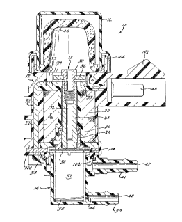
Referring to Figure 1 of the drawings, a sectional ~iew of
an electrically controlled vacuum regulator lO according to the
present invention is shown. The vacuum reyulator 10 includes an
encapsulated solenoid subassembly 12, a valve housing 14
connected to the bottom of the solenoid subassembly 12, and a
filter cover 16 connected to the top of the solenoid subassembly
12. The solenoid subassembly 12 includes a bobbin 20 having a
plurality of coil windings 22 wound thereon. A magnetic pole
piece 24 extends through the hollow center core of the bobbin 20.
The pole piece 24 in turn has a central bore 2~ formed therein
which serves as an air passageway and communicates with an air
inlet 18 ak the top of the solenoid subassembly 12. Atmospheric
air is admitted into the air inlet 18 through a filter 46 located
inside the filter cover 16.
The discharge of atmospheric air from the bottom of the pole
piece is controlled by a flat disc-type magnetic armature 30 that
is adapted to seat against a nonmagnetic member 28 surrounding
the lower end of the pole piece 24 and defining an annular valve
seat. In the preferred embodiment, the seat member 28 is made of
brass~
Surrounding the armature 30 is an annular-shaped magnetic
flux collector ring 34 that is connected to a magnetic L-frame
member 32. The L-frame member 32 includes an annular-shaped
upper segment 35 that surrounds the top of the pole piece 24. An
additional magnetic flux collector member 36 is spaced slightly
from the top of the upper segment 35 of L-frame member 32, as
-5-
well as from the top of pole piece 24, and is threadedly attached
to the top of pole piece 24 via a nonmagnetic calibration screw
50. Thus, when the solenoid is energized by current flow through
the coil windings 22, the magnetic flux path of the solenoid 12
i5 defined by the pole piece 24, the armature 30, flux collector
ring 34, L-frame member 32 including upper segment 35 thereof,
and flux collector member 36. The primary or workin~ air gap of
the solenoid assembly 12 is defined by the axial distance between
the bottom face of the pole piece 24 and the armature 30. In
addition, a secondary air gap in the flux path is created at the
opposite end of the pole piece 24 and includes a nonadjustable
portion defined by the radial distance between the pole piece 24
and the upper segment 35 of L-frame member 32, as well as an
a~justable portion defined by the axial distance between the top
end face of pole piece 24 and the flux collector member 36, as
well as the axial distance between the flux collector member 36
and the upper segment 35 of L-frame member 32.
The valve housing 14 connected to the bottom of the solenoid
subassembly 12 defines a chamber 52 below the armature 30 that
communicates with central passageways 40 and 42 formed in a pair
of laterally projecting connectors 39 and 41, respectively.
Connector 39 is adapted to be connected via suitable tubing (not
shown) to a source of full vacuum from the intake manifold of the
engine. Connector 41 is adapted to be connected via similar
tubing to the exhaust gas recirculation, or EGR, valve (also not
shown). The coil windings 22 of the solenoid assembly 12 are in
turn connected to the engine control computer via terminals 48.
A helical spring 38 is located in the chamber 52 of the valve
housing 14 for biasing the armature 30 against the annular valve
seat 28.
When the engine of a vehicle equipped with the vacuum
regulator 10 according to the present invention is not in
operation, the spring 38 holds the armature valve 30 against th~
valve seat 28 to thereby close the air passage 26 through the
pole piece 24. However, when the vehicle is in operation, a
negative vacuum pressure is introduced into chamber 52 of valve
housing 14 through the flow-restrictive orifice 44 in the
passageway 40, thereby tending to pull the armature 30 away from
the valve seat 28. Simultaneously, the engine control computer
energizes the solenoid 12 thereby exerting an attractive force
between the pole piece 24 and the armature 30 in opposition to
the effect of the vacuum from the intake manifold. The amount o~
vacuum, and hence the "vacuum signal"-, provided to the EGR valve
via passageway 42, is therefore controlled by the degree to which
the armature valve 30 is attracted toward the valve seat 28.
In particular, the sum of the forces exerted on the armature
valve 30 by the spring 38 plus the magnetic attraction of the
armature toward the pole piece 24 is equal to the product of the
vacuum pressure in the chamber 52 times the cross-sectional area
of the valve 30. Therefore, as the magnetic attraction force on
armature valve 30 increases, the level of vacuum pressure in
chamber 52 increases. Similarly, as the magnetic attraction
force on the armature valve 30 decreases, the level of vacuum
pressure in chamber 52 decreases. Accordingly, b~ controlling
the magnetic forcP exerted on the armature valve 30, which is in
turn controlled by the amount of current supplied to the solenoid
12, it is possible for the engine control computer to control the
amount of negative vacuum pressure or the "vacuum signal"
provided to the EGR valve. As previously noted, the degxee of
vacuum pressure provided to the EGR valve determines the amount
of exhaust gases that are introduced into the intaXe system of
the engine.
Referring additionally to Figures 2 - 9, a more detailed
description of the solenoid subassembly 12 as well as the
preferred manner in which the solenoid subassembly is constructed
and calibrated according to the present invention will now be
explained.
Initially, the bobbin 20, which is made of a durable
nonmagnetic plastic resin material, such as nylonl is wound with
coil wire 22 and the ends of the coil windings are terminated and
electrically connected to a pair of teL ;n~ls 48. The flux
collector ring 34 is installed on the bottom of the bobbin 20 and
the L-frame member 32 is installed with upper segment 35 thereof
placed over the top of the bobbin 20. As best shown in Figures
3a - 3b and 4, the lower segment of L-frame member 32 has a pair
of depending tabs 90 which are adapted to mate with corresponding
recesses 32 formed on opposite sides of the tab portion 94 of
ring member 35, thereby mechanically joining L-frame member 32 to
ring member 34. To ensure that the hole 46 formed in the upper
segment 35 of the L-frame member 32 is properly aligned with the
central axis of the bobbin 20, a locating hole 98 is provided in
-8-
'
the upper segment 35 which is adapted to receive the locating pin
99 integrally formed on the top of the bobbin.
With the flux collecting members 32 and 34 joined to the
wound bobbin 20, the entire subassembly is encapsulated in an
injection mold which forms the outer housing 100 of the solenoid
subassembly 12. The injection molding process completely
encloses and seals the solenoid subassembly 12 while
simultaneously forming the connector 102, the seating 1ange 104
for the filter cover 16, and the lower connecting flange 106 for
mating with the valve housing 14.
As noted above, the magnetic pole piece 24, which in the
preferred embodiment is made of steel, has a longitudinal bore 26
formed therein which serves as an air passageway through which
atmospheric air is discharged into the chamber 52 of the valve
housing 1~ when the armature valve 30 is open. The size of the
bore 26 toward the upper end of the pole piece 24 is enlarged and
has an internal thread 62 (Figure 5) formed therein for receiving
the calibration screw 50. Preferably, a section of straight
knurling 60 is provided on the outer surface of a slightly
enlarged portion of the pole piece 24 toward its lower end to
enhance the frictional bond between the pole piece and the valve
seat 28.
In particular, the nonmagnetic valve seat 28, which in the
preferred embodiment is made of brass, has a central bor~ 68
(Figure 6) formed therein having a diameter equal to the outside
diameter of the pole piece 24. Thus when the pole piece 24 is
inserted into the bore 68 of the valve seat 28, the slightly
_g_
.~ .
.
.
oversized knurled section 60 of the pole piece 24 will embed into
the inner walls of the valve seat bore 68 thereby creating a
tight frictional bond between the two parts. This is important
because the axial distance between the bottom face 66 of the pole
piece 24 and the bottom annular surface 74 of the valve seat 28
determines the working air gap between the pole piece 24 and the
armature 30 in the closed valve position of the fully assembled
device.
The lower portion of the valve seat member 28 has an
enlarged annular flange 70 which accommodates an enlarged shallow
counterbore 72 formed in the bottom face of the valve seat member
28. The resulting annular-shaped face 74 comprises the actual
valve seat and is machined in the preferred embodiment with a
slight radially outward back taper to provide a circular "line"
seal with the flat disc armature valve 30. During assembly, the
valve seat member 28 is installed on the lower end of the pole
piece 24 in a fixture that automatically sets the axial position
of valve seat surface 74 relative to the end face 66 of the pole
piece. In this manner, the primary air gap of the present vacuum
regulator remains constant from unit to unit. In the preferred
embodiment, the air gap distance is set between 0.008 - 0.010
inches.
The combined pole piece 24 and sea 28 subassembly is then
inserted into the enlarged bore section 80 tFigure 2) of the
bobbin 20 until the top of the pole piece 24 is substantially
flush with the top surface of the upper segment 35 of L-frame
member 32. The radial distance established between the pole
--10--
.. ~ '
piece 24 and the annular-shaped upper segment 35 of the L-frame
member 32 defines a secondary air gap in the flux path of the
solenoid 12.
To enhance the frictional bond between the seat member 28
and the bobbin 20, the outer diameter of the seat member 28 is
formed slightly larger than the enlarged bore section 80 of the
bobbin 20. In addition, the top portion of the seat member 28
includes a reduced diameter neck portion 76 which defînes a
flange 78 having its top outer edge 82 chamferred to facilitate
installation of the seat member into the bore 80 of the bobbin
20, and its bottom outer edge 84 defining a barb-like edge which
"bites" into the wall of the bobbin 20 to resist withdrawal rrom
the bore 80. Furthermore, the main body portion of the seat
member 28 preferably has knurling 86 formed around its outer
surface to further enhance the frictional bond between the bobbin
20 and the seat member 28. Since the bobbin 20 in the preferred
smbodiment is made from a nylon-type material, slight deformation
of the walls of bore 80 of the bobbin 20 occurs during
installation of the pole piece 24 and seat member 28 subassembly.
The elasticity of the bobbin material thus serves to tightly grip
the inserted pole piece/seat member subassembly. Note, the tight
seal formed between the bobbin 20 and the flange 78 of the seat
member 28 also serves to prevent the leakage of atmospheric air
around the outside of the seat member 28 into the chamber 52.
Turning now to Figure 7, the magnetic calibration flux
collector 36, which in the preferred embodiment is made of steel,
is press fit onto a nonmagnetic calibration screw 50, preferably
--11--
.
2 ~ 2 ~
made of hrass, until the flux collector 36 is flush against the
head of the screw. Optionally, the neck of the screw 50 may be
provided with vertical knurling to enhance the frictional bond
between the two components. The calibration screw 50 also has a
central bore 110 formed therethrough for providing the air inlet
18 into the air passageway defined by the central bore 26 in the
pole piece 24. In addition, the outer radial surface of the
calibration flux collector 36 is corrugated, as shown at 112, the
purpose of which will be subsequently described. The calibration
screw 50 is then threaded into the top of the pole piece 24 until
the calibration flux collector 36 is spaced slightly from the
upper segment 35 of L-frame member 32, thereby supplementing the
flux path across the secondary air gap between the top of the
pole piece 24 and the annular-shaped upper segment 35 of the
L-frame member 32. It should be noted tha~, in the preferred
embodiment, the diameter of the calibration flux collector 36 i5
such that it overlays the upper segment 35 of the L-frame member
32 so that the supplemental adjustable air gap created between
the flux collector 36 and the upper segment 35, as well as
between the flux collector 36 and the pole piece, is parallel to
the axis of the pole piece 24.
Finally, the armature 30 is disposed within the
circular-shaped cavity defined by an annular wall 114 (Figure 2)
integrally formed on the bottom of the bobbin 20. The inside
diameter of the annular wall 114 is slightly greater than the
diameter of the armature 30 to confine lateral movement of
armature. To facilitate air flow around the periphery o~ the
--12--
` .
.
.' ' . , ~ ~ ''
: '
armature 30 between the armature and the wall 114, the armature
preferably has a plurality of equally radially-spaced notches 116
formed around its periphery, as shown in Figure 8. OptiGnally,
and/or alternatively~ grooves may be formed in the interior
surface of the wall 114 to accomplish the same purpose. The
spring 38 is then installed in the chamber 52 of the valve
housing 14 and the valve housin~ secured to the mounting flange
106 of the encapsulated solenoid subassembly 12.
Once asse~bled, the vacuum regulator 10 is ready to be
calibrated. In order to calibrate the device, the terminals 4~
are connected to an electrical current source, connector 39 is
connected to a source of vacuum, and connector 41 is connected to
a vacuum gauge. A predetermined current signal is applied to
terminals 48 and a predetermined negative vacuum pressure is
applied through passageway 40, restrictive orifice 44, into
chamber 52. The calibration screw 50 is then rotated clockwise
or counterclockwise, as appropriate, to vary the reluctance in
the flux path of the solenoid 12 until the vacuum gauge
communicating with outlet passage 42 registers the desired vacuum
pressure signal. In particular, by adjusting calibration screw
50, the axial position of calibration flux collector 36 relative
to pole piece 24 and to upper segment 35 of L-frame member 32,
and hence the size of the supplemental portion of the secondary
air gap in the flux path of the solenoid, is varied. Moreover,
as will be appreciated by those skilled in the art, since the
flux path at the top of the solenoid assembly 12 has been divided
into two paths--the ~irst across the fixed radial air gap between
-13-
pole piece 24 and upper segment 35 and the second across an
adjustahle air gap between flux collector 36 and pole piece 24 as
well as upper segment 35--the adjustment of calibration flux
collector 36 affects the reluctance in only a portion of the flux
path, thereby making the adjustment less sensitive and thus
allowing for greater accuracy ~i~h less chance of oYershooting
the desired set point.
This advantage of the present invention is graphically
illustrated in Figure 10 which compares the output
characteristics of a vacuum regulator with an adjustable air gap
between the pole piece and the armature and a vacuum regulator
according to the present invention wherein the primary air gap is
fixed. Assuming a desired nominal output of 156 mm of mercury
(Hg) and an acceptable tolerance range of 12 mm Hg, it can be
seen that with the prior art vacuum regulator, the primary air
gap must be set within a tolerance range of approximately .001
inches, whereas with the vacuum regulator according- to the
present invention, the calibration flux collector 36 need be set
within a tolerance range of only approximately .008 inches.
Lastly, once the desired calibration set point is
established, a drop of an ultraviolet-cured polymer adhesive is
applied to the pocket 120 (Figure 9) formed in the top of the
housing 100 ad~acent the calibration flux collector 36. In
addition to providing an adhesive bond, the UV-cured polymer when
hardened serves as a "key" lock to mechanically prevent further
movement of the flux collector 36 relative to the housing 100 due
to the mechanical interference created between the hardened
--14--
polymer and the corrugated outer surface 112 of the flux
collector 36. Alternative means for securing the calibrated set
point are, of course, possible.
Finally, it is to be noted that the vacuum regulator 10
according to the present invention may be calibrated before
assembly of the valve housing 14 to the solenoid subassembly 12.
In particular, the solenoid subassembly lZ may be installed on a
calibration fixture that includes a chamber, spring, and
armature. However, the initially described approach is preferred
as it compensates for any possible variations in performance
attributable to differences in the characteristics of the
armature 30 and spring 38.
While the above description constitutes the preferred
embodiment of the invention, it will be appreciated that the
invention is susceptible to modification, variation, and change
without departing from the propPr scope or fair meaning of the
accompanying claims.
-15-
'