Note: Descriptions are shown in the official language in which they were submitted.
X ~,f ~
This invention relates generally to an excitation
and power control system using a programmable logic controller
(P.L.C. ) for monitoring the engine-generator unit in
locomotives. More specifically the invention relates to the
monitoring of input signais which are commonly controlled in
a locomotive during travel, determining the locomotive engine
performance, using this information to control the excitation
current to the main generator and storing, for a desired
period of time, the accumulated information respecting such
signals.
The excitation and power control system of the
present invention is not limited in its use to a particular
locomotive manufacturer or model. This system can be adapted
to substantially all diesel electric locomotives and offers
the option of standardization of control systems and of
maintenance personnel training. Furthermore, the system can
be easily expanded while maintaining use of the original
equipment.
An engine-generator unit includes a diesel engine
having fuel injectors and an engine speed governor and a main
electric generator connected to the engine. The speed and
power output of the engine are controlled by an engine speed
governor through the fuel delivery rate. The output power
control is effected by the field excitation level. The
generator drives the traction motors, located on locomotive
axles. The number of thè motors may vary. In a six axle
locomotive generally six such traction motors are used.
There are various types of locomotive excitation
and power systems presently in use. The engine speed is set
by the throttle lever position on the control stand. The fuel
supply is controlled based on the measured speed and throttle
lever setting. Mechanical linkages within the engine control
fuel and air consumption and output power. In some known
types of locomotives, a signal, representative of throttle
position, is sent to a throttle module, (an electronic board)
which provides a reference voltage based on that throttle
,~: -. - ,... ...
:,
~ t~ 3, .~ ?,
position. This reference signal is processed in accordance
with information such as the presence of wheel slip condit~on,
engine speed and the condition of the trail. A load
regulator, based on mechanical input from the engine, further
conditions the reference voltage (e.g. by reducing it, should
the engine speed (rpm) exceed its setting). The throttle
module also provides a stabilized control voltage (68 V) to
a sensor module. A performance control module takes both
voltage and current readings from the main generator and
processes them to provide a power control feedback signal.
By comparing the reference control signal with the power
control feedback signal from the performance control module,
` the control voltage enables or disables a sensing module to
send control (gating) pulses to electronic switches (SCR)
which provide an excitation current to the main generator.
The main generator converts the mechanical power into
electrical power for the traction motors, located on the
` locomotive axles.
In such a prior art system as heretofore described,
a proper correlation between fuel delivery rate and engine
speed is often not accomplished for the transitions between
power settings and load variations. In addition, the system
response to the transitions in power demand (as when the
track, terrain, temperature or fuel quality change) may
produce a response in field excitation of the generator which
is opposite in sense to the operator command.
` Some of the prior art excitation and power control
; systems for locomotives have replaced parts of the classical
system with microprocessors with a view to improving upon
conventional engine-generator control. For example, in the
invention of US Patent No. 4,498,016 (Walter Earleson et al)
;` the conventional engine speed governor was replaced with a
` microprocessor for fuel delivery, speed error control and
monitoring.
Although the prior art developments heretofore
discussed and particularly U.S. Patent No. 4,489,016 aforesaid
.
,
.~
have attempted to provide a system with wheel slip detection
means and to implement engine control for low speed (throttle
positions O or 1), the systems proposed do not integrate the
overall locomotive operations.
It is an object of the present invention to provide
an excitation and power control system for the diesel engine-
generator unit of locomotives, wherein by the use of a
programmable logic controller, the fuel delivery to the engine
is controlled by continuously monitoring the actual and the
desired (set) speed and the actual fuel delivery rate and
: accordingly correcting the excitation field to the generator.
The speed control, wheel slip control, traction motor
~` overload, dynamic brake and fan control functions are
; implemented by the use of programmable logic controller.
Another object of the present invention is to
provide an excitation and power control system which, by use
of a programmable logic controller, will substantially replace
switches and relays with electronic elements. Thus, the
control signals become logic (binary) electric signals. Large
multiple path relays and switches have been either removed
entirely or replaced with simple switches. On one application
~ of the present invention forty-one relays, three time relays,
`~i and sixteen electronic modules were replaced by the programmer
logic controller of the present invention. With cost
considerations being approximately equal, there are many
advantages for the proposed control system such as:
~' (a) the monitoring of locomotive parameters (i.e.
the input signals and the signals that are commonly controlled
~ during the travel);
`~ 30 (b) increase in the safety control means by the use
of software instead of electrical and electro-mechanical
connections and devices and by the adaptation of special
purpose electronics;
(c) improved engine fuel efficiency obtained by the
monitoring of travel conditions such as speed, track-load and
by implementing the auto shut down/auto start functions;
:
, .
.,
(d) miniaturization of the locomotive controls.
Another object of the present invention is to
provide an excitation and power control system which is not
limited in its use to a particular locomotive manufacturer or
model. The present invention can be adapted to substantially
all diesel electric locomotives thus opening the option of
standardizing and the possibility of readily expanding the
system while using original equipment.
A further object of this invention is to provide the
locomotive with an event recording system. A programmer logic
controller of the present invention can monitor and record up
to 1024 inputs and outputs compared to the 8 channels which
can be recorded in systems in actual use. The information may
be stoxed in either the PLC (in registers), or an external
hard disk or may be communicated through a modem to a remotely
located mainframe computer. The recorded information also
contains the alarms, the failures and other such details so
that the maintenance personnel could readily determine what
problems the locomotive has before it arrives for repair.
It is a further object of the present invention to
monitor the in and out periods of engine cooling fans so that
all fans will have the same number of working hours, replacing
the actual set sequence which does not utilize all fans for
the same amount of time.
According to one aspect of the present invention
an excitation and power control system for a diesel engine-
generator unit of a locomotive comprises:
a programable logic controller for processing input
signals received from a throttle lever switches module, a load
regulator module, a wheel slip transductor module and a
performance control module, and generates output signals which
control an engine speed governor and a sensor module: said
load regulator module, controlled by said engine speed
` governor according to a set throttle lever position and
generating a signal representative of a required power output;
said performance control module for processing a feedback
.
.; ,
~ J ~J ~
current and voltage signals from a main generator,
representative of a measured power output signal; said ~ensor
module for controlling the excitation current of said main
generator; a wheel slip transductor module for detecting wheel
slip condition, wherein the excitation current to said main
i generator is a function of difference between said required
power output signal and said measured power output signal and
at least a traction motor located on a locomotive axle.
These and other features and advantages of the
invention will be better understood from the following
description with reference to the accompanying drawings
wherein:
Figure 1 illustrates a block diagram of the
excitation and power control system for a prior art
locomotive;
Figure 2 illustrates a block diagram of the
` excitation and power control system for a locomotive according
to the present invention;
Figure 3a is a flow chart for the engine speed
control of the present invention;
Figure 3b is a flow chart for the wheel slip control
of the present invention;
Figure 3c is a flow chart for the traction motor
overload control of the present invention;
Figure 3d is a flow chart for the dynamic brake
control of the present invention;
Figure 3e is a flow chart for the fan control of
~ the present invention.
`~ A block diagram of the excitation and power control
` 30 system in actual use is embodied in Figure 1 and will be
^~ further described in order to provide a general description
` of typical modules and assemblies used in the system. In this
diagram, electrical power and electrical control signals are
illustrated by solid lines, while mechanical and hydraulic
connections are illustrated by broken lines. The voltage
reference regulator, located in the throttle (TH~ module 2,
.
:`~
.
.
:,
and the throttle lever switches 1 receive a 74V dc input from
an auxiliary generator. This signal is used to energize the
throttle response relays located in the throttle response
circuit of the TH module 2. The throttle response circuit
generates an output reference signal according to the set
throttle position. The voltage reference regulator output is
a stabilized 68 V dc level which is applied to the throttle
response circuit and to the sensor bypass (SB) module 9. The
reference signal from the throttle response circuit is applied
to load regulator (LR) module 5, through the rate control (RC)
module 3. This module limits the rate of change as the
throttle position is changed. A fast and smooth increase or
decrease in the reference signal is obtained. The reference
signal generated by LR module 5 is applied to the sensor
bypass (SB) module 9 as an input for the excitation and power
control loop comprising of SB module 9, the generator
excitation (GX) current regulator module 6, the generator
voltage (GV) regulator module 7, sensor (SE) module 10,
silicon controlled rectifier (SCR) 11, main generator 12,
current transformer 19, generator potential transformer (GPT)
~`~ 20, and performance (PF) control module 8. Excitation to the
main generator is determined by this reference signal from
~`` load regulator 5.
~ The load regulator 5 wiper arm position is
; 25 controlled by engine speed governor 14 so that the load on the
diesel engine (as well as engine rotation speed) is determined
by throttle position. The SB module 9 compares input
reference signal with feedback signals which are proportional
to main generator 12 output signals.
~` 30 Main generator 12 output signal is sensed by the
current transformer 19 and potential transformer 20. The
, current transformer 19 feedback signal is proportional to the
main generator output current. The potential transformer 20
feedback signal is proportional to the main generator output
voltage. The current feedback and the voltage feedback
signals are combined by tho performance modulo 8 to provide
,
~, .
s~ :1
a power control feedback signal. In some embodiments, a
performance control feedback signal is obtained by combining
the voltage feedback signal from a second potential
transformer, with the current feedback signal~ The power
- 5 control feedback signal is smaller than the performance
- control feedback signal during low current-high voltage
driving, and the performance control feedback signal is
smaller than the power control feedback signal during low
voltage high current operation. The two signals are applied
to the sensor bypass module 9. The SB module 9 compares the
reference signal from the load regulator 5 with the feedback
signals from the performance module 8. Whenever the value of
the reference signal is larger than the instantaneous value
of either one of the feedback signals, transistor Ql of the
sensor bypass module 9 is biased forward. The control signal
is applied thus to the sensor module 10, through the generator
excitation current regulator module 6 and the generator
; voltage regulator module 7. These two modules pass the
control signal as long as the main generator output voltage
; 20 and excitation current remain below the maximum safe value
and transistor Ql is forward biased. The GX module 6 blocks
the control signal if the generator excitation current rises
` above a safe value. The GV module 7 blocks the control signal
if the generator output voltage rises above a safe value. The
control signal (e.g. 68 volts) is applied to sensor module 10
which in response generates the gating pulses for silicon
controlled rectifier assembly SCR 11. The SCR 11 is forward
biased during each positive alternation of output voltage from
D14 alternator so that a pulse of a proper magnitude applied
to its gate will turn on the SCR diode, for a period as long
; as the SCR is forward biased. Excitation to the main
generator 12 from the D14 alternator is controlled by the
gating pulses which determine the SRC's conduction interval.
When the gating pulses are applied to SRC 11, excitation and
main generator output increase until the instantaneous
difference between the reference and the feedback signals is
....
- large enough to maintain the gating pulses generated by sensor
modules.
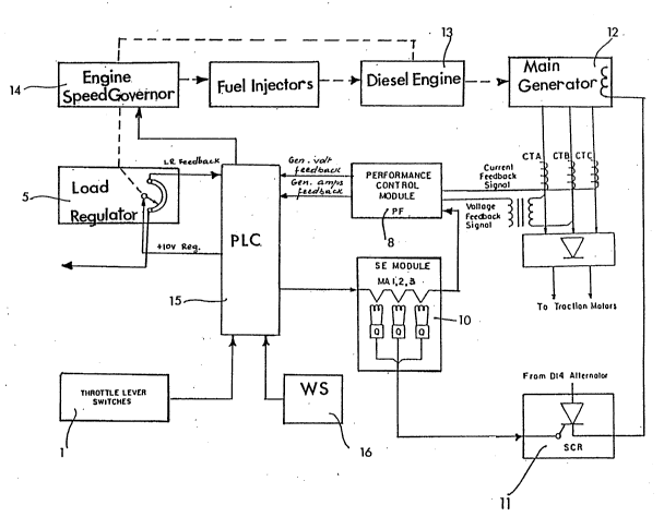
Figure 2 illustrates the block diagram of the
control of the present invention. On this figure the same
; 5 parts are represented by the same reference numerals as in
Figure 1.
The improvement introduced by the method of this
invention consists in eliminating the TH, the RC, the WS, the
SB, the GV and the GX modules conventionally used for
excitation control. The throttle lever switches 1 generate,
in the new arrangement, the input signals for a programable
logic control (PLC) 15. This unit energizes the appropriate
valves in the engine speed governor 14 and sets the engine
speed (rpm) levels. The PLC effects the logic control, the
recording functions, the device protection, supervises the fan
and thermostat cycling and the communication with a display
~` for maintenance. The mechanical feedback systems remain
unchanged.
` In the present invention the fuel delivery is
` 20 controlled by a conventional governor and load regulator
interfaced with the new control system. As an illustrative
example, once the control system acknowledges that the
governor operate in a specified throttle position, the
governor, as for the conventional systems, will control the
~` 25 engine speed and fuel delivery. The system will then take a
further reading from the load regulator to determine engine
~ performance and will use this information to control
`~ excitation current to the main generator.
` Power dips and overruns are corrected by modulating
the excitation current and making this a function of the
difference between power output required and power output
measured. This control is obtained with a closed loop control
system which can measure and react in "real time" (less than
20 milliseconds).
The feedback signals are received from the
performance control module 8 as it is being done by SB module
:,~
.
.:
; `
,?,
9 according to the block diagram of Figure 1. A constant
voltage (typically 10 V) is applied to the load regulator 5
to monitor the engine response. This voltage level of +lOV
is used as a lower limit for the load regulator, when the
throttle takes low positions (O or 1). This feature of the
invention was designed because accessory items, such as
locomotive lights, compressors and the like, which are either
in or out and are easily detectable in the low throttle
positions by the system, will consequently be processed as
changes in the load, which is undesirable. The +lOV voltage
will invalidate the control loop at low speed. The feedback
from the load regulator 5 will be conditioned mathematically
within the programmable logic controller 15 based on throttle
setting. This conditioned feedback will be compared to the
performance control module feedback. When LR feedback signal
is higher than the performance module feedback signal, a
signal proportional to the difference is applied to the SE
module 10 to close the excitation control loop. The wheel
slip transducers 16 are used by PLC 15 to sense wheel slip
conditions and their severity. The PLC elaborates an
appropriate system response.
There are two types of input signals to programmable
logic controller, these being digital and analog signals.
Digital signals take the value of O volts (logic
"O") or 74 volts (logic "1"). These signals constantly
indicate to the logic unit what contractor, switch or train
line wire is powered. These contactors and switches
identified by numerals 10001-10080 in the program are:
contactors for series parallel connection of traction motors,
trunk sand switch which notifies the reader if the engineer
is calling for a sand generator field switch; a motor brake
switch-gear which reports whether the braking position is on
or off; switches for high temperature, emergency fuel cut-off
switches etc. The program stored in programmable logic
controller memory monitors all the inputs, makes the logical
.
decision based on their value and responds by either
energizing or de-energizing the logic outputs.
Another category of input signals is the analog
signals. These signals are variable and are calibrated by
passing through a transducer or a voltage divider be~ore
entering the programmer logic controller, in order to achieve
the required level. The analog inputs are changed to either
signals in the range of O-lOV or 4-20 mA. These signals
represent dynamic brake lever position, main generator
voltage, main generator current, grid current, speed, wheel
slip bridge current (representative of a detected wheel slip
condition) and wheel slip transducer current. The
programmable logic controller compares the inputs to a
registered information representing optimum travel parameters
` 15 in order to generate output control signals based on
; programming.
The output signals of the programmer logic
controller can be classified into two categories - the real
and the internal outputs.
The real outputs drive either contactors, lights,
switch-gear or switches. These components are used on
locomotives today. According to this invention, they are
driven using software generated signals which replace relays
and electro-mechanical modules. Some of the components which
`~ 25 may be replaced by software according to the present invention
are sanding, throttling, wheel slip, extended braking,
excitation limit, generator voltage and generator excitation
modules.
~` The second category of outputs is internal outputs
`~` 30 used for PLC internal control logic.
; The information concerning the locomotive travel
is recorded and stored. It is accessible to the engineer or
to the maintenance personnel with a display. The s t o r e d
information includes the power consumption, the time when
throttle portion has changed, dynamic bra~ing ti=e, etc.
`
,
;: `
The alarm signals are also recorded and stored
They acknowledge a faulty condition of the engine such as hot
engine, low oil pressure, low water level, overspeed, fan
failure, motor brake failure, contactor failure, etc All
alarms are displayed as an alarm condition, i e they are
; listed on the display with the time and date of occurrence
In one embodiment, the traction motor voltage and
the current are monitored to detect if a difference over 10%
in the values of current and voltage appears When such a
situation is detected it is recorded also as an alarm
condition. These records are of a great help for maintenance
personnel who can diagnose a possible motor failure (e.g.
faulty brushes or insulation breakdown) before a consequent
major failure.
The block diagram of Figure 2 will be best
understood when considered in conjunction with the flow
diagrams of Figure 3a - 3e showing the implementation of the
functions of the present invention.
`` Figure 3a illustrates how the engine speed is
changed according to the position of the throttle. Speed is
a parameter in a performance equation where maximum track
adhesion is obtained through precision control of excitation
current. The excitation current is reduced or removed in
overspeed situations.
On a six axle locomotive, traction motors operation
can assume one of two configurations. When starting up and
at low speeds, traction motors operate as three independent
(parallel) sets of two traction motors electrically connected
`~` in series. This mode of operation is known as series-parallel
` 30 and it is set up to take place during the high current-low
~ voltage operation of the generator. At high speeds, these
`~ same traction motors are all connected in parallel across the
generator output. This takes place during the low current-
high voltage operation of the generator. The change from
series-parallel operation to parallel operation is known as
forward transition operation. This happens when the main
; generator voltage exceeds a preset limit and the current drops
below a preset limit. During forward transition, the traction
motors are disconnected and reconnected through an automated
procedure. If the engine-generator set is not preconditioned
before this happens, the instant change from a load to no load
condition will result in an instant uncontrollable increase
in engine RPM. This presents a high probability of engine
and/or generator damage. Additionally, the generator field
needs time to decay so that contactors are opened and
reconnected under "no load" conditions. Braking or closing
contactors under load is undesirable being highly destructive
under certain conditions. The transition point is set by
P.L.C. based on the speed value. Should one of traction
motors fail, the system will automatically switch back to the
voltage and current control board on throttle position.
The program checks if the throttle position has
changed. If the throttle position has not changed, the coil
for that internal throttle position control stays energized.
If the throttle setting has changed, an internal function n
takes a new value according to the new setting. This function
is a four variable function (current, voltage, rotational
speed of the engine and value of excitation). If the new
setting requires an increased/decreased rotational speed of
the engine, this new corresponding value is read and the value
of excitation is accordingly increased/decreased in steps,
until the actual excitation value becomes equal to the
excitation value corresponding to the set throttle position.
The new set of parameters is stored in the four fields of the
function n replacing the old values. These new values will
be considered the reference value for the next changes in the
throttle position.
Figure 3b shows a flow chart for the program
controlling the wheel slip. Three preset values of slip
control signals (namely STAGE1, STAGE2, STAGE3) represent
~` 35 threshold values for different severity levels IVALl , IVAL2,
IVAL3. The control system of the present invention
-
.
;:
J rJ
13
incorporates different responses to those three levels o~
wheel slip. If the detected wheel slip condition belongs to
the first stage (i.e. is moderate), sand is applied to ra~l~
When the wheel slip condition is more severe and it belongs
5 to a second stage (i.e. is sharp) the excitation current i5
reduced and sand is applied to rails. In the situation when
the wheel slip condition belongs to the third level, in
addition to sand and excitation reduction, the "Over Ride
Solenoid" on engine speed governor is energized (this drives
10 load regulator position to minimum). In the situation where
the wheel slip condition surpasses the third level (i.e.
; surpasses the admissible level), excitation is removed and an
annunciation device is activated.
" The threshold values can be changed as desired
15 depending on the locomotive model or other factors that are
taken into consideration. A wheel slip condition at high
speed is much more serious than wheel slip on a locomotive
; ~ust starting to pull a load. This system utilizes locomotive
track speed as a factor in their response to wheel slip
20 detection. As shown in the flow chart of Figure 3b the
signals from the wheel slip transductor 16 are continuously
monitored. The difference between two successive values
~` (IDIFF) is compared with the threshold values in order to
determine the level of severity of wheel slip conditions and
25 accordingly, the above described steps are followed. The HP
signal representative of the motor power is checked in order
~`~ to determine if it is a high or low speed wheel slip. For
;` various levels of wheel slip conditions, the signal HP is
reduced or increased to the set point value, which corresponds
30 to the throttle position.
Figure 3c shows the functioning of the traction
motor overload condition control. The current values are
read every second and are compared with four preset threshold
values in order to determine three intervals for the degree
"3S of motor load. The values for this embodiment are 4300A,
4400A, 4800A and 6000A. A counter is increased with 6, 2 or
:.
.~
. . .
.
14
1, depending upon the interval in which the read value (AMPS)
belongs, up to a limit of 1800. When the counter limit is
reached, according to the time interval in which the limit wa~
reached, an overload condition is detected and its severity
is evaluated. As a result, the maxim current set limit is
decreased for a period of time (SEC-VAL). After this time the
cycle is restarted with the initial values for the current and
voltage values.
Figure 3d is a flow chart of the dynamic brake
control. Dynamic braking consists in the use of traction
motors to slow down the locomotive in place of the traditional
mechanical brake shoes. This is done by electrically
positioning the traction motors across a bank of resistors
(grid resistors) which provide a load. The traction motor
output is a function of the value of these resistors and the
excitation current provided by the main generator. The
excitation current is a function of the position of the
variable brake lever controlled by the operator. Where the
resistance of the resistors is variable, track speed also
becomes part of the function which determines the braking
force. Main generator excitation also needs to be controlled
so that the maximum current allowable through the resistors
is not exceeded.
Dynamic brake starts by checking if the conditions
which validate this control are met. Dynamic brake lock-out
signal, invalidating the dynamic brake control may be
activated manually by use of a switch or automatically by the
`~ PLC in the case of a problem. It is reset manually. When
~ braking operations is initiated the voltage on the braking
`~ 30 rheostat on the locomotive control stand will change its value
between O and 68V, according to the lever position. (variable
GRID SET in the flow chart). This range is translated in this
embodiment in a range of current between 0 and 700A (in fact
the voltages under 10V are translated in a OA current and the
voltage over 53V are treated as asking for full 700A). The
set value of the current is read and the generator field is
:`
-
~i;'./'f',.,~,JJ
modified to a value according to the brake lever position.
This value is limited to 700A and the wheel slip condition is
controlled. Should the measured voltage surpass 550V, for
safety reasons the faulted condition is acknowledged and the
dynamic braking is locked-out (by lock-out signal~. Depending
on the range of the braking, extended range dynamic brake
contactors (expressed by variable CONTACTOR (p) in the flow
chart of which there can be two or three depending on the
application) short out a section of the grid resistors in
order to maintain a high braking current for speeds less than
18 mph, so that the braking action can be maintained at slow
speeds. The PLC keeps the dynamic current between 550A and
700A. If current drops below 550A, an extended range
condition will be energized. If the speed increases and the
current tends to overpass the admissible limit of 700A, a
contractor will be de-energized. During the dynamic braking
the high voltage ground condition and the dynamic braking fan
operation are checked and should the tests results be
unsatisfactory, the dynamic braking is interrupted by lock-
out signal. These fans cool the grid resistors and if they
; are not operational, the PLC will interrupt the braking in
order to save the grids from melting. In order to prevent a
false warning which may occur occasionally when fan can not
be started, the control voltage becomes a logic condition for
the lock-out function. When the unit is in self load, (i.e.
loading of the main generator takes place through dynamic
brake grids) the lock-out signal is conditioned by a level of
at least 75V. During dynamic braking the control voltage
" must be greater than 10V.
Figure 3e is a flow chart of the fan and thermostat
controls. On this flow chart, THERM (N) represents the state
of the thermostat number N and the FAN(M) represents the state
of the fan number M. These variables have as many fields as
many thermostats or fans are present in the system. A "O"
value represents the "off" setting and a "1" value for these
variables represents the "on" setting of a thermostat or a fan
.
: "
.
16
respectively. The variable OFFTEMP and ONTEMP represent the
respective switch setting for thermostats variables N_T_O and
N_F_O represent the number of thermostats or fans which are
"on" and #THERM represents the total number of fans ~or
thermostats). As can be seen from the flow chart, the fans
are started sequentially and accordingly, the counters N_T_O
and N_F_O count the number of thermostats and fans which are
` "on".
In order to reduce the fuel consumption, the
autostart and auto shutdown of the units is used. The units
are off for a period of time, their temperature and air
i pressure is monitored and when the operating range for these
parameters is reached, the unit auto starts. This monitoring
is effected by thermocycle in engine water, ambient air, oil
and main reservoir air pressure. While only certain
embodiments of the present invention have been described, it
will be apparent to those skilled in the art that various
changes and modifications may be made therein without
departing from the spirit and scope of the present invention
as claimed in the following claims.
. .