Note: Descriptions are shown in the official language in which they were submitted.
- 20256 1 2
GAS SEPAR~TION BY SEMI -PERMEABLE MEMBRANES
This invention pertains to the field of gas
separation and, more particularly, gas separation by
the use of semi-permeable membranes. More
specifically, the present invention relates to the
separation of gaseous components which are frequently
present in various gas stream mixtures found in the
production and/or reaction of polycrystalline and/or
epitaxial silicon metals.
Polycrystalline and epitaxial silicon metals
employed in semi-conductor usage are typically produced
by the reduction and decomposition of silicon
tetrachloride, trichlorosilane, dichlorosilane and/or
silane. These silicon containing gaseous compounds are
typically mixed with large concentrations of hydrogen
gas and reacted at activation temperatures sufficient
to effect reduction and decomposition
. ;
~~ - 2 - 202561~
whereby to deposit silicon metal by 6uch reaction on
predetermined 6ubstrates.
Thus, for example, in the production of
polycrystalline 6ilicon by a process commonly
referred to as the Siemens-type process,
trichlorosilane is reacted with hydroqen to form
polycrystalline 6ilicon on a heated elongated
starter rod positioned within a bell-jar reactor, as
described in U.S. Patent No. 3,979,490. In an
alternative process, as described in U.S. Patent No.
4,150,168, silane is thermally pyrolyzed in such a
bell-jar type reactor in the presence of hydrogen to
form the polycrystalline 6ilicon on the elongated
6tarter rod.
Instead of a bell-jar type reactor, a
fluidized bed has also been utilized to form
polycrystalline silicon on seed particles as
discussed in U.S. Patent Nos. 3,012,861 and
3,012,862.
Silane, which may be used as a precursor
material for the formation of the polycrystalline
6ilicon, may be prepared by disproportionation as
disclosed in U.S. Patent No. 3,968,199 or by
reduction of metallurgical 6ilicon as discussed in
U.S. Patent No. 4,676,967.
So too, in the preparation of silicone
compounds, 6ilicon metal i6 generally
hydrochlorinated to an intermediary product 6tream
D-15,636
_ 3 _ ~2~S ~2
comprising trichloro6ilane and hydrogen from which
intermediary stream the final 6ilicone compounds are
ultimately prepared.
In essentially all of these technigues,
there are gaseous ~treams produced which contain gas
mixtures of one or more gaseous silicon compounds,
~uch as halogenated halosilanes, and the like, which
are in admixture with hydrogen and hydracids such as
hydrogen chloride, and the like. Such gas mixtures
may be present in intermediary process streams,
waste streams, by-product streams, or even product
streams as well.
Frequently, it is desirable to be able to
separate these gaseous silicon components from the
hydrogen or gaseous hydracids for purposes of
purification and/or recovery of these various
components. Processes which are currently available
for such separation are generally either
economically undesirable or are not very effective
in achieving the desired separation. Indeed, in a
number of instances, such as in the thermal
pyrolysis of silane to form polycrystalline silicon,
the exhaust gas consisting of silane and hydrogen is
~imply flared rather than attempting to separate the
silane from the hydrogen.
A need accordingly exists for providing a
technique in which the components of such gaseous
mixtures may economically and efficiently be
~eparated.
D-15,636
4 ~025612
By virtue of the present invention, a new
technique has been discovered which is capable of
effectively separating gaseous silicon compounds from
hydrogen or hydracids in an economical and
efficient manner.
More particularly, these gaseous components
may be separated by contacting such a gaseous stream
with a suitable semi-permeable membrane to effect such
separation. Such a semi-permeable membrane may include
-an asymmetric membrane having a thin separation layer
which determines the overall gas separation
characteristics of the membrane. Alternatively, the
semi-permeable membrane may also include a composite
membrane comprised of a porous support layer having
substantially no separation characteristics with
respect to the gaseous components and a substantially
non-porous separation layer positioned on the support
layer which substantially determines the selective
permeation characteristics of the overall composite
membrane.
Accordingly, in one aspect, the present
invention is directed to a method for separating at
least a first gas selected from the group consisting of
- H2, HX and mixtures thereof contained in a gaseous
mixture from at least a second gas selected from the
group consisting of SiXaH2 and mixtures thereof;
where X = a halogen ion,
a = O to 4,
b = O to 4, and
a + b = 4
contained in said gaseous mixture, which method
comprises passing the gaseous mixture from the reactor,
via a recycle line, to a separator containing a semi-
permeable membrane which exhibits selected permeation
1,
202~6 1 2
of the first gas over that of the second gas;
separating at least a portion of the first gas from the
second gas by contacting the gaseous mixture with one
surface of the semi-permeable membrane which exhibits
selective permeation of the at least first gas over
that of the at least second gas; and removing from the
vicinity of the opposite surface of the semi-permeable
membrane via a second line, a permeate having a
concentration of the at least first gas which is
greater than the concentration of the at least first
gas in the gaseous mixture.
In preferred embodiments of the present
invention, composite membranes are utilized to carry
out the specified separation.
A particularly preferred composite membrane
which provides excellent separation and permeation as
well as excellent chemical stability and resistance to
the gaseous silicon components and the hydracids is a
separation layer comprised of sulfonated-polysulfone
and a support layer comprised of polysulfone.
The description of the present invention
which follows refers to the accompanying drawings,
wherein:
Figure 1 is a schematic diagram of a
polysilicon production process utilizing a membrane
separator in accordance with the present invention to
separate silane from hydrogen.
Figure 2 is a schematic diagram of a process
in which an intermediary stream containing a
~D?56 12
mixture of at least trichlorosilane and hydrogen
from a silicone production process i6 treated so as
to recover trichlorosilane utilizing a membrane
separator in accordance with the present invention.
- Figure 3 is a schematic diagram of an
apparatus used for measuring the permeability of a
gas through a semi-permeable membrane.
Figure 4 is a graph showing the
permeability of trichlorosilane through a sulfonated
polysulfone composite semi-permeable membrane as a
function of time as measured by the apparatus of
Figure 3.
Figure 5 is a graph ~howing the
permeability of nitrogen and helium through a
sulfonated polysulfone c~mposite semi-permeable
membrane as a function of time as measured by the
apparatus of Figure 3, both before and after the
membrane had been exposed to trichlorosilane.
Figure 6 is a graph showing the
permeability of hydrogen chloride through a
sulfonated polysulfone composite semi-permeable
membrane as well as the permeabilities of both
nitrogen and helium, respectively, both before and
after the membrane was contacted with the hydrogen
chloride.
Figure 7 is a graph showing hydrogen
recovery as a function of stage cut through a
D-15,636
7 202561 2
sulfonated polysulfone composite semi-permeable
membrane for a given set of feed conditions for a feed
containing hydrogen, nitrogen and trichlorosilane.
Figure 8 is a graph showing the
concentration of nitrogen and trichlorosilane as a
function of stage cut through the sulfonated
polysulfone composite semi-permeable membrane used for
the measurements set forth in Figure 5 for the same set
of feed conditions.
Figure 9 is a graph showing the
concentration of hydrogen as a function of stage cut
through the sulfonated polysulfone composite semi-
permeable membrane used for the measurements set forth
in Figure 5 for the same set of feed conditions.
Figure 10 is graph showing the size of the
membrane surface area required for a given stage cut
for the sulfonated polysulfone composite semi-permeable
membrane used for the measurements set forth in Figure
5 for the same set of feed conditions.
While the present invention is primarily
directed to the field of polycrystalline and epitaxial
silicon production and/or silicon reactions, it is
understood that the invention is
- 8 - 20256~ ~
not limited exclusively to thi~ technological
field. Rather, the invention is directed to the
separation of the type of gaseous comro~entE which
are typically found in such 8 ilicon
production/reaction techniques but which may be
present in any other processing environment.
Typically, the gaseous 6ilicon compounds,
in addition to silane (SiH4), are generally
chlorinated silanes such as silicon tetrachloride
(SiC14); trichlorosilane (SiC13H);
dichlorosilane (SiC12H2); and monochlorosilane
(SiClH3). Inasmuch as hydrogen i~ primarily
utilized for reduction and/or disproportionation
purposes, in addition to such hydrogen being present
in the gas streams, hydrogen chloride (HCl) may be
present as well.
By virtue of the present invention, it has
been di covered that semi-permeable membranes,
particularly composite membranes, can effectively be
utilized to separate these gaseous silicon compounds
from the hydrogen or hydrogen chloride. As is well
known to those 6killed in the art of membrane
technology, when referring to a number of gaseous
components contained in a gas mixture, there may be
a number of such components which will readily
permeate through a ~emi-permeable membrane at a rate
which is much greater than other components
contained in such gas mixture. Those components
which do, in fact, permeate at a relatively faster
rate are typically referred to as ~fast~ gases for
D-15,636
2Q25~ ~
g
that particular qaseous mixture as compared to the
"slow" gases which permeate at a lesser rate or not
at all. With respect to a mixture of gaseous
silicon co...~ounds and hydrogen or hydrogen chloride,
we have learned that the silicon compounds are
"~low" gases as compared to the hydrogen and
hydrogen chloride which are "fast" gases. As a
result of appreciating that there is such a
difference in permeation rates between the gaseous
silicon compounds and the hydrogen or hydrogen
chloride, we have realized that semi-permeable
membrane separation was possible. However, and most
importantly, we have also discovered that there are
membranes, particularly composite membranes, which
not only have excellent separation and permeability
characteristics but which are, additionally,
chemically resistant to these gaseous silicon
compounds which typically have a corrosive nature.
Although the process for the production of
pure polycrystalline silicon primarily utilizes
silane or chlorinated silane precursor materials,
the present invention is not limited to only the
separation of the chlorinated form of these
compounds. Indeed, gaseous silicon compounds
containing other halogen ions, namely, bromides,
iodides, and fluorides, may be separated from
hydrogen and/or HCl, HBr, HI or HF. Accordingly,
the present invention is capable of effectively
separating one or more slow gaseous components
selected from the group consisting of ~iXaHb
from one or more fast gaseous components selected
D-15,636
2 ~ ~ ~ 6 1 r~
from the group consisting of H2 or ~X, wherein
X e Cl, Br, I and Fl,
a ~ 0 to 4,
b ~ 0 to 4, and where
a ~ b - 4.
To achieve selective 6eparation, the
semi-permeable membrane must exhibit less resistance
to the permeation of one or more components than
that of at least one other component contained
within the gaseous mixture. Thus, selective
separation ean provide preferential depletion or
eoncentration of one or more desired components in
the mixture with respect to at least one other
component and therefore provides a product having a
different proportion of the one or more desired
components to the at least one other component than
that proportion in the mixture.
However, in order for membrane separation
of one or more desired components to be commercially
attractive, the membranes must not only be capable
of withstanding the conditions to which they may be
subjected during the separation operation, but also
must provide an adequately selective separation of
the one or more desired components, i.e., a high
separation factor, as well as a sufficiently high
flux, i.e., a high permeation rate, 80 that the use
of such a separation procedure is carried out on an
economically attractive basis.
D-15,636
ll- 2`02561~
With respect to reactive, gaseous silane-
containing 6treams, alteration of the chemcial
~tructure of the membrane may occur, particularly if
a polymer-based membrane i6 utilized. ~uch
alteration may sometimes be acceptable if it does
not lead to deterioration of long term membrane
performance. By virtue of the present invention, as
a preferred embodiment, it has been determined that
composite membranes, particularly sulfonated
polysulfone on polysulfone composite membranes, are
capable of providing desirably high separation
factors and high permeation rates with respect to
the gaseous components discussed above, including
excellent chemical stability.
Asymmetric type membranes are comprised
essentially of a single permeable membrane material
distinguished by the existence of two distinct
morphological regions within the membrane structure.
One region comprises a thin, dense semi-permeable
skin capable of selectively permeating one component
of a fluid mixture. The other region comprises a
less dense, porous, non-selective support region
that serves to preclude the collapse of the thin
~kin region of the membrane under pressure.
Composite membranes generally comprise a
thin layer or coating of a ~uitable essentially
non-porous membrane material 6uperimposed on a
porous substrate. ~his coating layer, also referred
to herein as a separation layer, determines the
6eparation characteristics of the composite
D-15,636
2~)25~
- 12 -
6tructure, and i~ advantageou61y very thin 60 as to
provide the desirably high permeablity referred to
above. The 6ubstrate or support layer only 6erves
to provide a 6upport for the membrane layer
positioned thereon and has 6ubstantially no
6eparation characteristic6 with respect to the
gaseous mixture being ~eparated or concentrated.
These membranes may be fabricated in
various 6hapes, 6uch as (1) a flat 6heet which may
be supported in a typical plate and frame 6tructure
6imilar to a filter press; (2) a flat 6heet rolled
into spirals with 6pacing materials interleaved with
the membrane and the assembly sealed to provide
6piroidal channel6 permitting the passage of the
feed on one side of the coiled membrane to the
opposite 6ide of the membrane; (3) as tubes lining
the inner 6urface of a reinforced braid, the braid
itself at times being a component in a larger tube;
or (4) in the form of open-ended hollow fibers so
organized and sealed into header plates so as to
provide a separation of the flow over the external
6urfaces of the hollow fibers from any flow within
the bores of the hollow fibers ensuing by virtue of
passage of the gaseous feed mixture across the
membrane. Such hollow fiber construction is
preferred in the process of the present invention
The invention is further described herein,
for convenience of description, with particular
reference to hollow fiber composite membranes. It
will be under6tood, however, that the 6cope of the
D-15,636
- 13 - 2~$612
present invention is not limited to the use of the
membranes in the composite structure in the hollow
fiber form.
The hollow fiber membranes typically used
in the art have continuous channels for fluid flow
extending between the exterior and interior
surfaces. Freguently, the pores have an average
cross-sectional diameter less than about 20,000
Angstroms and in some hollow fibers the
cross-sectional diameter i6 less than about 1,000 or
5,000 Angstroms. Advantageously, the walls of the
hollow fibers are sufficiently thick that no special
apparatus i6 required for their handling.
Frequently, the hollow fibers may have outside
diameters of about 20 to 1,000 microns, generally
about 50 to 1,000 microns, and have walls of at
least about 5 microns in thickness, generally about
50 to about 1,000 microns thick. The wall thickness
in some hollow fibers may be up to about 200 or 300
microns. The coating may have a thickness ranging
from about 0.01 to about 10 microns and preferably
has a thickness of about 0.05 to about 2 microns.
In order to provide desirable fluxes
through the hollow fibers, particularly using those
hollow fibers having walls at least about 50 microns
in thickness, the hollow fibers may have a
substantial void volume. Voids are regions within
the walls of the hollow fibers which are vacant of
the material of the hollow fibers. Thus, when voids
are present, the density of the hollow fiber is less
D-15,636
l~- 2~)25~1~
than the density of the bulk material of the hollow
fiber. Often, when voids are desired, the void
volume of the hollow fibers is up to about 90,
generally about 10 to 80, and sometimes about 20 or
30 to 70, percent based on the superficial volume,
i.e., the volume contained within the gross
dimensions, of the hollow fiber. The density of the
hollow fiber can be essentially the same throughout
its thickness, i.e., isotropic, or the hollow fiber
can be characterized by having at least one
relatively dense region within its thickness in
barrier relationship to fluid flow through the wall
of the hollow fiber, i.e., the hollow fiber is
anisotropic. Generally, a relatively dense region
of anisotropic hollow fibers is essentially at the
exterior or interior of the hollow fiber, and
preferably, the coating contacts this relatively
dense region.
The material used for the hollow fiber may
be a solid, natural or synthetic substance. The
selection of the material for the hollow fiber may
be based on the heat resistance and/or mechanical
strength of the hollow fiber, as well as other
factors dictated by the separation process of the
present invention and the operating conditions to
which it will be subjected. Most importantly, the
materials used, whether it be the porous support
layer or the essentially non-porous coating layer
must be chemically resistant to each of the gaseous
~ilicon compounds and hydracids noted above. The
hollow fibers may be flexible or substantially rigid.
D-15,636
2û~S6I2
The hollow fiber~ may be comprised of an
inorganic material, e.g., hollow glass, ceramic,
~intered metal, or the like. In the case of
polymers, both addition and co~densation polymers
which can be fabricated in any suita~le manner to
provide porous hollow fibers, are included.
Generally organic, or organic polymers mixed with
inorganic materials (e.g., fillers), are used to
prepare the hollow fibers. Typical polymers can be
substituted or unsubstituted polymers and may be
selected from polysulfones, ~uch as bisphenol A
polysulfone ~old under the mark "Udel" by Union
Carbide Corporation) or polyether sulfone (sold
under the mark "Victrex" by Imperial Chemical
Industries); polyacrylonitriles; polyethers;
poly(arylene oxides) such as poly(phenylene oxide);
polyether ketones; polysulfides; polymers from
monomers having alph-olefinic unsaturation other
than mentioned above such as poly(ethylene),
poly(propylene), poly(butene-l), poly(4-methyl
l-pentene), polyvinyls, e.g., poly(vinyl chloride),
poly(vinyl fluoride), poly(vinylidene chloride),
poly(vinylidene fluoride), and the like.
~ ubstrates prepared from polysulfone are
particularly preferred.
The polysulfone or other hollow fiber
substrates employed in the practice of particular
embodiments of the present invention can be prepared
in accordance with conventional technigues well
D-15,636
- 16 - ~2~6~2
known in the art. Hollow fibers are generally spun
from a dope composition of the desired fiber
polymer, guenched, washed and dried. A~ disclosed
by Cabasso, et al. in "Composite Hollow Fiber
Membranes", Journal Of Applied Polymer ~cience,
Volume 23, 1509-1525 (1979), and in "Research and
Development of NS-l and Related Polysulfone Hollow
Fiber6 for Reverse Osmosi~ Desalination of
~eawater", Gulf south Research Institute, July 1985,
Distributed by National Technical Information
Service, U.S. Department of Commerce Publication PB
248,666, polysulfone hollow fibers can be spun from
a ternary solution of polysulfone, poly(vinyl
pyrrolidone) and dimethylacetamide, with the total
polymeric concentration in the solution desirably
being ~0 to S2 weight %, and the polysulfone/poly-
(vinyl pyrrolidone) ratio being 1.5:2Ø The well
known tube-in-tube jet technigue is disclo~ed as
being suitable for the spinning procedure, with
water at about 21C being the preferred outside
quench medium for the fibers. The quench medium in
the center of the fiber is desirably air. Quenching
is typically followed by washing the fibers, for
example, conveniently with hot water at about 50 to
60C. Following such washing, the hollow fibers are
dried prior to being coated with the separation film
layer to form the desired composite membrane. For
this purpose, the polysulfone hollow fibers are
typically dried by passage through a hot air drying
column for a suitable period of time.
D-15,636
- 17 - 2 ~2 5~ ~ z
Hollow fiber substrates are typically
substantailly porous and the extent of their 6urface
and bulk porosity is controlled by dry/wet, wet, dry
or melt extrusion technigues which are well ~nown to
those skilled in the semi-permeable membrane art.
The porcsity of the hollow fibers may be further
modified by solvent annealing or high temperature
annealing technigues.
The coating layer of the composite membrane
is in the form of an essentially non-interrupted
membrane, i.e., an essentially non-porous membrane,
in contact with the porous support layer.
The materials for the coating may be
natural or synthetic 6ubstances, and are often
polymers. Synthetic substances include both
addition and condensation polymers. Typical of the
useful materials which can compri~e the coating are
polymers which can be substituted or unsubstituted,
and which are solid or liquid under gas separation
conditions, and include synthetic rubbers; natural
rubbers; relatively high molecular weight and/or
high boiling liquids; organic prepolymers;
poly(siloxanes) (silicone polymers); polysilazanes;
acrylonitrile-containing copolymers; polyesters
(including polyarylates); cellulosic polymers;
polysulfones, especially modified polysulfones;
poly(alkylene glycols) such as poly(ethylene
glycol), poly(propylene glycol), etc.; polymers from
monomers having ~-olefinic unsaturation 6uch as
poly(olefins), e.g., poly(ethylene),
D-15,636
18 20256 ~ 2
poly(butadiene), poly(2,3-dichlorobutadiene),
poly(isoprene), poly(chloroprene), poly(styrene)s
including poly(styrene) copolymers, e.g., styrene-
butadiene copolymer, poly(vinyl halides) (e.g.,
poly(vinyl bromide)), poly(vinylidene halides),
fluorinated ethylene copolymer, poly(arylene oxides),
e.g., poly(xylylene oxide); polycarbonates; and any
interpolymers including block interpolymers containing
repeating units from the above, and grafts and blends
containing any of the foregoing. The polymers may or
may not be polymerized after application to the porous
support layer.
Particularly useful materials for coatings
comprise cellulose acetate, silicon rubber, and ethyl
cellulose. Most preferably, a sulfonated polysulfone
is utilized as the coating material for the composite
membrane. Such sulfonated polysulfones are discussed
in, for example, U.S. Patent No. 3,709,841, U.S. Patent
No. 4,054,707, U.S. Patent No. 4,207,182, European
Patent Application 0,202,849, European Patent
Application 0,165,077 and European Patent Application
0,202,841. Sulfonated-polysulfones are also discussed
in the Journal of Applied Polymer Science, Volume 20,
pages 1885-1903 (1976) in an article entitled
Sulfonated PolYsulfone by A. Noshay, et al.
- 19- 2~5~
Polyarylethersulfone with at least one
sulfonic acid group present on one of the aromatic
rings is one of the more common ~ulfonated
polysulfones which is applicable ~n the present
invention. Such a polyarylethersulfone generally
has ~he formula as follows
~C~
J~
Sulfonated bisphenol A polysulfone is
particularly preferred as the coating for the
6eparation layer for the composite membrane.
As used herein, the term "sulfonic group"
is meant to be an optionally salified --S0 H
group, for example the groups --S03, l/nMn~
where M represents an NH4 ion, an alkali metal
ion, an alkaline earth metal ion, or a transition
metal ion (of valency n).
- The sulfonation of polysulfone can be
carried out in accordance with the procedures
described in, for example, U.S. Patent No.
3,709,841. Suitable sulfonating reagents include
chlorosulfonic acid (ClS03H) which is a preferred
sulfonating agent. However, it is also possible to
use, for example, sulfurtrioxide and its addition
product~ with Lewis bases containing oxygen as the
electron donor atom; sulfuric acid and fuming
sulfuric acid can al60 be u6ed. The sulfonation
D-15,636
- 20 - ~ ~25
reaction is generally carried out at -50 to +80C,
preferably at -10 to +35C, in solution in a
601vent for the polyarylether sulfone which i6 inert
as regards the sulfonation reaction. Halogenated
hydrocarbons, especially methylene chloride,
1,2-dichloro-ethane and 1,1,2,2-tetrachloro-ethane
are suitable ~olvents.
The amount of sulfonating agent employed is
generally such that the ratio of the number of
sulfur atoms of the sulfonating agent to the number
of sulfur atoms of the non-sulfonated
polyaryl-ether-sulfone is from about 0.3 to about 6,
and preferably from about 1.2 to 4. The exact
number of sulfo groups which can be fixed to the
non-sulfonated polyaryl-ether can of course be
altered by adjusting the sulfonation conditions and,
in particular, the temperature, the duration of the
reaction, and the concentration of the reagents.
The sulfonated polyaryl-ether-sulfone produced can
be isolated in accordance with the method described
in, for example, U.S. Patent Nos. 3,709,841 or
3,875,096.
Other methods for the preparation and
isolation of a sulfonated polysulfone, known in
principle from the prior art, can be adopted, by
analogy, to prepare such sulfonated polysulfones.
8ulfonated polyarylethersulfones with
degrees of ~ubstitution between about 1.0 to about
2.5 meg/g of dry polymer that are soluble in
D-15,636
21 202561 2
solvents such as methoxyethanol, nitromethane, and
alcohol/water mixtures are particularly useful for the
preparation of the composite membranes capable of
effectively separating gaseous silicon compounds from
hydrogen or hydracids.
The dried polysulfone hollow fiber is coated
with the coating solution of the sulfonated-polysulfone
and is then dried. Such a coating and drying sequence
may comprise the teçhn;que used and described in the
Coplan et al patent, U.S. Patent No. 4,467,001. Thus,
the dried hollow fibers are passed through the coating
solution contained in a coating vessel, and is then
passed through a drier oven and a cure oven for contact
with drying air or other suitable gas, and higher
temperature curing air or other gas prior to being
taken up on a winder or otherwise being processed or
stored for eventual incorporation in membrane modules
suitable for use in the desired separation operation.
For the coating of polysulfone hollow fibers with the
sulfonated polysulfone, which is a preferred embodiment
of the present invention, it is generally desirable to
employ drying temperatures of from about 20C to about
100C. Those skilled in the art will appreciate that
it is also possible to dry the separation layer on the
support layer without employing the separate curing
step noted above.
In a preferred embodiment of the present
invention, the support layer is subjected to a high
- 22 - 2~25~12
temperature annealing proces~. Although it i6
preferable to anneal the substrate prior to its
being coated with the ~eparation layer, the
annealing proces6 may be carried out on the coated
substrate as well. The resulting composite membrane
formed from ~uch an annealed sub6trate, provides for
an even greater enhancement in both separation and
permeation characteri6tics.
Polysulfone fibers may, for example, be
annealed by drying freshly spun fiber~ at 115C by
passage through a hot-air drying column which fibers
are then annealed by passing them through another
hot-air oven at a temperature of about 182C in the
case of bisphenol A polysulfone which is close to
its glass tran~ition temperature of about 184 to
186C. The residence time in the oven is generally
about 5 seconds to 4 minutes, preferably about 10 to
30 seconds.
In use, the composite membrane will
generally be assembled as part of a membrane
separating device. The membrane device is designed
to carry out a 6elective separation of at least one
component from a fluid stream mixture. The membrane
apparatus will typically consist of an enclosure and
a membrane assembly positioned therein. The
membrane assembly can be constructed in the form of
a spiral wound cartridge, a hollow fiber bundle, a
pleated flat sheet membrane assembly, and like
assemblies common in the membrane industry. The
membrane as6embly is constructed so as to have a
D-15,636
- 23 -
~25~
feed-~urface 6ide and ~n opposite permeate exit
~ide. The enclosure is con6tructed so as to enable
the feed ~tream mixture to be brought into contact
with the membrane feed-6urface side. ro~d~it means
are provided for the removal of the part of the feed
stream that did not permeate through the membrane,
and for the separate removal of the permeate
components that have passed through the membrane.
In conducting the gas ~eparations,
including concentrations, of the present invention,
the exit side of the membrane is maintained at a
lower thermodynamic potential for the at least one
permeating, fast component, i.e., H2 or HX, than
the thermodynamic potential at the feed side. The
driving force for the desired permeation through the
membrane is a differential in thermodynamic
potential across the membrane, for instance, as
provided by a differential in partial pressure.
Permeating components pass into and through the
membrane and can be removed from the vicinity of the
exit side of the membrane to maintain the desired
driving force for the permeation. The functionality
of the membrane does not depend upon the direction
of feed flow or the surface of the membrane which is
first contacted by the gaseous feed mixture.
The gaseous mixture sent to the membrane
separator can range from atmospheric to at least
2000 psig, generally about 50 to about 3000 psig,
and preferably about 100 to about 200 psig.
D-15,636
~ ~ - ~
2~25612~
- 24 -
The temperature of the gaseous mixture can
vary from below ambient to about 100C, generally
about ~0 to about 80C, and preferably about 50 to
about 70C.
The concentration of the fast gas, i.e.,
the hydrogen or hydracid, may be present in the
gaseous mixture to any extent. Thus, the
concentration of the hydrogen and/or hydracid may
vary from as low as 1 % by weight to as much as 99 %
by weight, generally about 1 to 50 % by weight.
It i~ understood, of course, that in
addition to the at least one hydrogen and/or
hydracid gas that may be present in the gaseous
mixture and the at least one gaseous silicon
compound that is also present in the gaseous
mixture, other fast and slow gases may be present as
well. Accordingly, during the separation process
utilizing the composite membrane, these extraneous
fast gases may also be permeated through the
permeation membrane in conjunction with the hydrogen
and/or hydracid gases.
As used herein, it will be understood that
the selectivity, or separation factor, of a membrane
or membrane module assembly represents the ratio of
the permeate rate of the more permeable (the fast
gas) component to the less permeable (the slow gas)
component of the gaseous mixture being ~eparated
which permeability is expressed in ft3 (STP)/ft2
day psi.
D-15,636
202~
- 25 -
Typically, the permeation rate of hydrogen
through the composite membrane at room temperature
(25C) may be anywhere in the range of from about
0.1 to about 10.0 ft3 (STP)/ft2 day psi,
and more typically is in the range of from about 0.5
to about 4.0 ft3 (STP)/ft2 day psi. Of
course, this permeation rate is dependent upon the
process conditions, and most importantly is
dependent upon the particular semi-permeable
membrane being utilized.
Similarly, the permeation rate of hydracids
~uch as hydrogen chloride at room temperature (25C)
is in the range of from about 0.1 to about 10.0
ft3 (STP)/ft2 day psi, and more typically
in the range of from about 0.2 to about 5.0 ft3
(STP)/ft2 day psi, and is again dependent
upon the process conditions and the specific
composite membrane being utilized.
Correspondingly, the separation factor
between-the fast gas components of the present
invention, i.e., the hydrogen and hydracids, and the
gaseous Eilicon compounds, is typically in the range
of from about 20 to about 2,000, and more typically
is in the range of from about 50 to about 500 (at
25C), again dependent upon specific process
conditions and the particular composite membrane
being utilized.
D-15,636
202~
- 25 -
Typically, the permeation rate of hydrogen
through the composite membrane at room temperature
(25C) may be anywhere in the range of from about
0.1 to about 10.0 ft3 (STP)/ft2 day p8i,
and more typically i6 in the range of from about 0.5
to about 4.0 ft3 (STP)/ft2 day psi. Of
course, this permeation rate is dependent upon the
process conditions, and most importantly is
dependent upon the particular 6emi-permeable
membrane being utilized.
Similarly, the permeation rate of hydracids
such as hydrogen chloride at room temperature (25C)
is in the range of from about 0.1 to about 10.0
ft3 (~TP)/ft2 day psi, and more typically
in the range of from about 0.2 to about 5.0 ft3
(STP)/ft2 day psi, and is again dependent
upon the process conditions and the specific
composite membrane being utilized.
Correspondingly, the separation factor
between-the fast gas components of the present
invention, i.e., the hydrogen and hydracids, and the
gaseous silicon compounds, is typically in the range
of from about 20 to about 2,000, and more typically
is in the range of from about 50 to about 500 (at
25C), again dependent upon specific process
conditions and the particular composite membrane
being utilized.
D-15,636
- 26 -
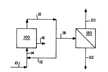
In Figure 1, a schematic diagram is 6et
forth 6howing how the present invention can be
effectively utilized in the 6ilane decompo6ition
process for the production of polycrystalline
silicon. In particular, 6ilane is introduced to
pyrolysis reactor 100 via line 10 which joins with
recycle line 12 containing unreacted silane and
by-product hydrogen and is passed into the reactor
via line 14.
Reactor 100 may comprise a fluidized bed
reactor containing a bed of 6ilicon seed particles
or, alternatively, may compri~e a bell-type reactor
containing a silicon starter rod. In either type of
reactor, the silane is thermally decomposed to
deposit metallic silicon on the 6ilicon 6eed
particles or silicon starter rod, respectively. As
a result of such decomposition of the silane,
hydrogen is produced as a by-product. Since the
conversion of the silane to silicon metal is not
complete, the unreacted silane, including the
hydrogen by-product is typically recycled back to
the reactor as 6hown by line 12. Silicon metal
product is removed from the reactor via line 16.
In order to reduce the build-up of hydrogen
in the recycle loop, however, a purge stream 18 must
generally be provided. In the prior art 6uch purge
~tream would generally be flared and any silane
contained therein would 6imple be lost. In the
present invention, however, 6uch 106s is avoided by
passing the purge stream containing both 6ilane and
D-15,636
2(~25~
- 27 -
hydrogen into a ~emi-permeable membrane separator
120.
8eparator 120 is provided with a cellulose
acetate composite membrane having a polysulfone
substrate. The permeate, which i~ that material
passinq through the membrane, has a much higher
concentration of hydrogen, which is a fast gas, as
compared to the raffinate, which is that material
which does not pass through the membrane and
contains a high concentration of the silane, the
slow gas in this feed ~y~tem. The permeate,
containing substantially hydrogen, is passed out of
the separator via line 20. The raffinate,
containing substantially silane, is passed out of
the separator via line 22. The recovered silane in
line 22 may be recycled back to reactor 100 (not
shown) or utilized in any desired manner.
Turning to Figure 2, a schematic diagram is
presented showing how the present invention can be
utilized to treat an intermediary stream from a
silicone compound production process in order to
effectively and economically 6eparate
trichlorosilane from hydrogen.
In particular, in the preparation of
silicone compounds, silicon metal is generally
hydrochlorinated to an intermediary product stream
comprising trichlorosilane and hydrogen from which
intermediary ~tream the final silicone compounds are
ultimately prepared. The trichlorosilane is
D-15,636
202~12
- 28 -
required to be ~eparated from this ~tream for
further proces~ing to produce the desired ~ilicone
products. Generally, ~uch separation has been
carried out by refrigeration. Such refrigeration
techni~e is uneconomical inasmuch as a large amount
of energy i~ wasted to cool the non-condensable
hydrogen gas. Moreover, the heat transfer from the
gas phase to the concensed phase is very poor.
Consequently, the prior art has had to provide large
refrigeration units to accomplish the required heat
transfer.
In the present invention, however, a
membrane separator is utilized to accomplish a major
~eparation of the trichlorosilane from the hydroqen
to thereby produce a ~tream concentrated in
trichlorosilane which is only then subjected to a
refrigeration ~tep. Clearly, the refrigeration unit
in the process of the present invention is
substantially smaller than that required by the
prior art.
Accordingly, an intermediary stream
containing trichlorosilane and hydrogen is first fed
to a flash tank condenser 300 via line 30 to
condense a portion of the trichlorosilane which
leaves the condenser via line 32. The
trichlorosilane/hydrogen stream, now containing a
reduced amount of trichlorosilane, leaves the
condenser via line 34, passes through heater 310 and
is then introduced to membrane ~eparator 320 via
line 36. The ~tream is heated in heater 310 60 as
D-15,636
202~6~2
~ - 29 -
to prevent any condensation of trichlorosilane in
the membrane separator. Condensation might occur if
the partial pressure of the trichlorosilane in the
raffinate i6 equal to the vapor pressure of the
trichlorosilane. Membrane separator 320 contains a
ulfonated polysulfone composite membrane.
The majority of the hydrogen contained in
the gas mixture pemeates through the membrane and
leaves as the permeate through line 38. The
raffinate now containing a concentrated amount of
trichlorosilane with some hydrogen is then passed
via line ~0 into a pre-cooler 330 in preparation for
being introduced into refrigeration unit 340 via
line 42. In refrigeration unit 340, the
trichlorosilane is separated from the remaining
hydrogen by condensation. ~ubstantially pure
trichlorosilane leaves the refrigeration unit via
line 44 and substantially pure hydrogen leaves the
unit via line 46. The trichlorosilane is then
processed in accordance with conventional techniques
to form the desired silicone compositions.
While the process described in Figure 2 has
been focused upon the prouction of trichlorosilane
for the purpose of 6ilicone compositions, it is
understood that the same process may also be
utilized for the 6eparation of trichlorosilane along
with minor amounts, if any, of dichlorosilane,
silane, and/or silicon tetrachloride from hydrogen
in a process which utilizes such gaseous silicon
compounds for the formation of polycrystalline
D-15,636
2Q2561 ~
- 30 -
silicon or epitaxial silicon, such as by the
Siemens-type process.
The invention is hereafter further
described with respect to various illustrative
examples thereof. It should be understood, however,
that such examples should not be construed as
limiting the scope of the invention which is set
forth in the appended claims.
EXAMPLES
Example I
To test the chemical stability of various
membrane materials to the presence of silane, a
particularly corrosive gaseous silicon compound, a
number of membrane materials are exposed to silane
in test cells for a period of time and then compared
to untreated examples using the following techniques:
Fourier Transform Infrared
8canning Electron Microscopy
Energy Dispersive X-Ray Spectroscopy
X-Ray Photo Electron 8pectroscopy
The materials tested included polysulfone,
polyolefin, polyvinylchloride, and cellulose
acetate. These materials are exposed at 30 psig at
room temperature for up to 14 days.
The results of thi~ exposure analyzed by
each of the four techniques noted above show that
D-15,636
2025612
- 31 -
the chemical ~tability of these materials in the
presence of silane is guite acceptable.
Example II
The permeability of trichlorosilane was
measured using a dynamic method with the apparatus
shown in Figure 3.
The apparatus is comprised of two sections,
namely, a permeation assembly shown in Figure 3 by
dotted line 100 and a feed assembly designated by
solid line 200. A bomb 210 contains liguid
trichlorosilane. The permeation assembly includes a
membrane separator 220 comprised of a sulfonated
polysulfone coating on a polysulfone substrate
composite membrane, a coil 230, and a pressure
transducer 240. Valve 260 controls flow of material
into the membrane separator. Valve 280 controls the
flow of trichlorosilane leaving bomb 210, and valve
300 controls the flow of material entering through
line 12.
Both the feed and permeation assemblies
were placed in oven 500. The permeation assembly was
wrapped with heating tape to keep its temperature
T2 higher than the oven temperature Tl to
prevent any condensation in the membrane separator.
Checking for condensation was done through the
pressure transducer. Thus, if, for example, T2 is
kept at 55C-and Tl i6 set at 50C, then if the
pressure transducer shows the vapor pressure of
trichlorosilane at 50C, then it is known that there
D-15,636
202~6~2
- 32 -
i~ no condensation taking place in the membrane
6eparator.
A permeate i6 removed from the 6eparator
through line 14 and a raffinate is removed from line
16, respectively, and its compositions are analyzed.
Example III
Using the apparatus of Example II,
measurements of trichlorosilane permeability were
taken and are set forth in Figure 4. Pigure 4 is a
graph of pressure ratio as a function of time where
the "Y" coordinate of (P-Po)/(Pl~Po)
represents:
PO ~ pressure on permeate side of membrane
Pl ~ pressure on feed side of membrane at
time egual to zero, i.e., at the start of the
experiment
P = pressure at any given time
At the start of the experiment, the ratio
of (P-Po)/(Pl~Po) is egual to 1. As the
experiment continues, if the ratio becomes less than
1, this is an indication that the material being
tested is permeable through the membrane. For a
material that i~ not very permeable, the ratio of
(P-Po)/(Pl~Po) remains substantially close to
1.
D-lS,636
202~ 2
- 33 -
For the trichlorosilane, as can be seen
from Figure 4, the results of the mea6urements show
that it i6 impermeable inasmuch as the membrane
pressure does not decrease with time. In6tead, the
membrane pressure increases slightly with time and
then levels off. This slight increase in pressure is
due to the permeation of nitrogen from the permeate
~ide of the membrane. The nitrogen in the permeate
side is used to purge moisture out of the membrane
6eparator
Example IV
Once again using the apparatus of Example
II, and further to the measurements taken in Example
III, before and after the membrane separator was
exposed to trichlorosilane, permeability
measurements were made for both helium and
nitrogen. The results of those measurements are
shown in Figure 5 using the same set of coordinates
as Figure 4.
The "I" and "II" set forth to the right of
the graph in connection with He, and the "I", "II",
and "III" ~et forth in connection with N2,
respectively, refer to separate runs that were made
with these materials through the membrane. The "I"
run was con6idered a purging run.
As can be seen, after the membrane
separator was contacted with the trichlorosilane,
the helium permeability did not change at all while
D-15,636
202~612
- 3~ -
nitrogen permeability increased. However, after the
membrane ~eparator was repeatedly pur~ed with
nitrogen, the nitrogen permeability decreased with
time and gradually approached the original
permeability that was measured before the membrane
was exposed to the trichlorosilane.
Example V
Once again using the permeating apparatus
of Example II, the permeabilities of helium and
nitrogen were measured, both before and after the
membrane was exposed to hydrogen chloride. Hydrogen
chloride permeability was al~o measured.
The results of those measurements are shown
in the graph set forth in Figure 6 in which the same
coordinates as that of Figure 4 are used.
The results of these measurements reveal
that hydrogen chloride permeates faster than helium
and that the separation factor of hydrogen chloride
with respect to helium is 1.2. 8econdly, these
results al~o show that the membrane ~eparator is
~table in the presence of hydrogen chloride inasmuch
as the permeabilities of both the helium and the
nitrogen remained constant, even after the membrane
was exposed to the hydrogen chloride.
Example VI
Hydrogen permeablity and silane
D-15,636
~02~6 1 2
- 35 -
permeability through a 5 ft2 composite membrane
compri6ing a cellulose acetate coating on a
polysulfone ~ubstrate was al80 tested. The results
are 6hown in Table I below.
Table I
H2 Permeability, SiH4 Permeability
and Separation ~actor for SiH4-H~ Mixture
Temp (C)....... ......32
(P/6)H2......... .Ø2843
(P/6)SiH;....... ..2.43 x 10 3
~(H2/SiH4)...... 117
~ Unit, ft3 (STP)/ft2 psi day
As can be seen, the value for the separation factor
of hydrogen with respect to silane is 117. The
silane permeablity remains the same even after the
membrane separator was exposed to silane for over
216 hours. This indicates that chemical interaction
between the silane and the components of the
composite membrane was not present and the membrane
remain chemically 6table.
The membrane separator was tested by using
D-15,636
2~2~S~
- 36 -
two hydrogen/~ilane gas mixtures: one containing
48.8 mole percent silane and the other containing
1.0 mole percent silane. The operating conditions
of these two tests are ~et forth in Table II below.
Table II
Operating Conditions for
SiH4-H2 Membrane Separation
Test 1 Test 2
Feed Composition ~8.8% SiH4 1% SiH4
(molar) 51.2% H2 99% H2
Feed Pressure: 89.7 psia 89.7 psia
Permeate Pressure 25.7 psia 25.7 psia
Temperature: 34~37C 34-37C
The results of these two tests are set
forth in Tables III and IV below.
D-15,636
2 ~ 1 2
- 37 -
Table I~I
Feed Flowrate ~tage Cut Y~2 ~ 2
l/hr ~ % %
278.77 0.09 9'7.23 47.68
99.59 0.23 96.52 41.85
46.12 0.29 92.4 30.34
21.74 0.36 9D.98 24.00
8.34 0.52 83.57 16.12
YH2 ' H2 molar concentration in permeate
2 ~ H2 molar concentration in raffinate
~ - Stage cut, permeate flowrate/feed
flowrate
Determined from the mass balance:
2 ~ 8 34 l/hr x 0.512 - 4.336 l/hr x .8357
4.0 l/hr
D-15,636
202~
- 38 -
Table IV
~eed Flowrate 8tage Cut YH2 XH2
- l/hr ~ % %
516.4 0.19 lOo .0 98.59
136.9 0.70 99.92 96.37
114.9 0.82 99.87 94.75
84.3 0.98 99.75 75.11
D-15,636
2~2~
- 39 -
Example VII
Having determine~ the permeabilities for
both hydrogen and trichlorosilane, a membrane
separator can now be sized and the separation
performance predicted.
The operating conditions of the membrane
separator, using a sulfonated polysulfone coated
polysulfone composite membrane with hollow fiber
length of about 1 foot, are set forth in Table V
below:
Table V
Feed Temperature: 90C
Feed Pressure: 45 psig
Permeate Pressure: S psig
Feed Flow Rate: 22.39 lb mol/hr
Feed Composition:
Gas Mol. % Flow rate, lb mol/hr
H2 71.78 16.0
N2 3.09 0.69
8iHC13 25.13 5.60
100.00 22.29
D-15,636
202~2
Because the trichlorosilane i~ not permeable
through the membrane as determined earlier, it can
be assumed that the separation factor of hydrogen
with respect to trichlorosilane is about 2,000.
Graphs showing the separation peformance and the
size of separator are shown in Figure 7 through 10
which have been briefly described earlier.
The stage cut in these figures is defined as
the ratio of the permeate flow rate to the feed flow
rate. The pinch point occurs at a stage cut where
the partial pressure of hydrogen in the permeate
side is egual to the partial pressure of hydrogen in
the raffinate side. When this happens, no net
hydrogen transfers from the raffinate side to the
permeate side. Accordingly, the separator is
desirably designed to have a stage cut below the
pinch point. The value for the stage cut in this
design should therefore be less than or equal to
0.58 as shown in Figure 7.
Figure 7 shows that 80% of the hydrogen can be
removed from the feed at a stage cut egual to 0.58,
i.e., the pinch point. The concentration of
triclorosilane, the concentration of nitrogen
(~igure 8), and the concentration of hydrogen in the
permeate at the pinch point (Figure 9) are 0.2s%,
0.95% and 98.8%, respectively. Accordingly, from
Figure 10, it is determined that the surface area
required for the membrane at the pinch point for the
feed condition~ noted in Table V is approximately
7,000 ft .
D-15,636