Note: Descriptions are shown in the official language in which they were submitted.
2 ~? ~ J
. )~)()/(J~615 PCT/SE90/OnO31
Ah'~ PARATU~ FOR DE'~'~TrR~;G A~.D SOUE~gI~G ~ T-~I~.L
The present invent~on relates to an apparaus for d~watering
and squeezing material in form of sludge, sediment, sus-
penfiions such as paper pulp, peat, etc.
Drior art
In fabrics 6uch as pulp and paper industries, water cleaning
plants etc, applications exi6t were dewatering of suspen~ions
takes place f-om dry substances of some tenths procent up to
hiahest possible dry content, for instance 40-50~. Such
dewatering operations are carried out today usually in one or
WO 5 teps.
, 15
For dewaterlng within above mentioned area and in one step
wire bænd pres~es, some types of cyllnder pres6es and 80
called sieberdrumpresses are today p.referabely used.
The di5ad~antages with such equipment is that the machines
are expensive, require large floor 6pace, are expen6ive ~n
maintenance, are sens`itive for operation disturbance6, et-.
For dewatering in said area and in two steps for lnstance
different type of filters or drum dewaters are today used for
step 1 and usually screw pres9es for ~tep 2. The dewatering
in step 1 takes place from actual inlet concentration up to
for instance 10-12~ and in ~te.p 2 from this valua up to
highest possible concentration.
:~ ~ilters or drum dewaters and screw presses used in this
" connection are considerably simple machines and have accor-
dingly lowar price, are cheaper ~n maintenance and are
machines reliable in running.
..
-~
;
WO~ X~S ~ PCT/SE90/00031
~he dlsadvantages ~n dewater-ng in two steps and in separate
machlnes are, however, above all that the apparatuses must
for distribution technical reasons be placed a distance from
each other in the fabric meaning that the press material must
be transported between the sites of the machines. This
results in lncreased costs for the installation, requir0s
', larger building volume, increases the energy requirement for
' the operation, etc,
Our Swedish patent No, 870065a-1 ~Publ, No, 456 149) dis-
clo6es a scre~ press consisting of a feed screw and sieve
, mantle surrounding the feed screw, A faed section ia arranged
: ahead of this screw press and this feed section comprises a
feed screw and a sieve mantle surrounding this 6crew. Thifi
i5 first mentioned feed section is formed for dewatering mainly
by self-drainage and the ~ection has a rotating sieve mantle
provided with means for cleaning holes in the 6ieve mantle,
The Present i~vention
The present invention haa a press &ectian principally simular
to that de6cribed and shown in our above mentioned Swedish
patent, 3eæide this, however, the present invention differs
essentially ~rom the apparatus according to said patent.
Moreover, the above mentioned di6advantages have by the
present invention been eliminated by providing a unit in
which dewatering and squeezing take place in one machine.
Dewatering and squeezing ta~e place in a æimple and
operatively reliable construction at the same time as the
advantages with a compact dewatering fun-tion is obtained and
the need of intermediate transport devices are eliminated.
The characterizing of the invention in order to eliminate the
ahove mentioned disadvantages and in order to obtain above
2`~ )v~
W~ )X~ PCT/SE90~00031
.
mentloned adavantage6 i8 that ahead of the screw prese
section and ln direct connec~lon to this section lS to a
dewaterlng device ln the form of a drumfilter, disc filter,
bow sleVe, etc, arranged an out-~eed section connected t.o the
dewatering device, said out~feed section including an
out-feed 3crew and a trough surroundiny thi~ screw and s~id
press ~crew of said screw press section and i~s ~ieve mantle
. being an elongation of and being arranged on the same central
line as the out-feed screw and trough of the out-feed
section, respectivily, and that to the dewatering device
arranged adjacent the out-feed section is arranged an inlet
for the material to be treated and an outlet device for
tranferring the material from the dewatering device to the
out-feed flection.
; 15
Summing up, the apparatus according to the invention thus
consists of a combined dewatering part and screw pres~ part,
the dewatering part consisting of a dewatering device s~lch as
a fllter, a drum dewa~ering device, a bow sieve, etc, to
; 20 which is connected an out-feed screw and the screw press ?art
being connected as an elonga~ion to the out-feed screw of the
dewatering device.
Such a combination according to the inventlon gives essentual
advantage~ which are not predictable when using each machine
itself.
Such a~vantages are for instance the foilowing:
- a compact unit resulting in lower investment co~t,
: 30 - smaller space requirement,
- lower eneryy requirement for the operation ~no intermediate
transport devices, etc),
- a unit operating with alternatively positive or negative
pressure wherein the press part serves as a sealing plug
.-
.`.
~ .
W~0/~ }~5 ~ J PCT/SE~)0/00031
devlce agalnst the atmospherlc pressure,
- slmpler guidlng of a single unit,
- infeed to the screw press in axial direction as distln-
guished from laterally infeed to a screw press which
; 5 usually requires separate lateral infeed device and such a
lateral lnfeed device is not required in the apparatus
according to the mention,
- the connection according to the lnventlon makes it easier
to optimize the operation over the apparatus. For instance,
the output of the filter can be increased and thereby lower
outgoing concentration from the filter be accepted and
instead carried out a more powerful dewatering in the screw
press part. In for instance machines placed apart from each
other in the fabric such a balance in the operation is
lS essentially more complicated to carry out and control.
Above mention and other advantages will be evident from the
following description of embodiments of the invention with
reference to the acompanying drawings.
Desc~iption of drawinas
Fig. 1 is a horisontel view showing a combined apparatus of
filter/screw press section.
Fig. 2 shows a section I-I in Fig. l.
Fig, 3 shows a horisontel view in larger scale of another
embodiment of an apparatus according to the invention and
shows more in detail the outlet part of the out-feed screw
; from the filter and the screw press section connected to this
part .
`.- .
..
.`~ -
.-~
.~
2~ J ~ ~
0/0~5 PCT/SE90/00031
Fig. 4 shows still another embodiment of an apparatus accor-
ding to the invention.
Descri~tion of_embodiments
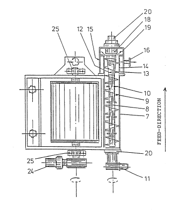
The embodiment o~ a filter having outfeed acrew and screw
pres~ as shown in Figs. 1 and 2 has a shute 2 for material
inlet 1 and a intermediate wall or overflow 3 which delimits
; 10 the shute 2 from a trough 4 in which a drum 5 is immersed.
The drum is covered with a filter cloth 6.
On opposite side o~ the inlet 1 there i~ a trough 7 ~or
receiving the material path 22 formed on the filter cloth 6
lS of the tilter drum 5. A d~vice for disintegration and outfeed
of the material path i8 arranged in the trough 7. This device
consists of a ~crew core 8, thread sections 9 on the core and
pins 10 arranged between these sections. Drive means 11
; arranged for the screw.
In the elongation of the outfeed screw 8 there i5 arranged a
device for compre6sion and squeezing of the material. This
pres~ section consists of a screw core 12 diverging in the
feed direction and a continuous thread helix 13 arranged
about the core and surrounded by a perforated sieve cylinder
14. For collecting the water 6queezed out throuyh the sieve
cylinder 14 there is arranged a sealing mantle 15 and a
connection piece 16 for the di6charged of the squeezed water.
At the material outlet 19 from the press there i3 a reci-
procating throttle device 18 by means of which the dry
content of the squeezed material can be adjusted. ~he mate-
ri~l is collected in a shaft 17 and falls downwardly for
further transport. ~aarings for the screw cores 8 and 12 are
de:ign~ted with the reference numeral 20.
:
., .
.~.
:..
2 ~'J~
WO~)0/0~645 PCT/SE90/00031
The water dralnaged off the filter drum 5 lS dlscharged
through a fall chute 23 and the material layer 22 for~ed on
the drum i~ directed by means of guard board 21 down into the
trough 7. Drive means 24 is arranged for driving the filter
drum 5. The ~ilter drum i5 journalled in two conventional
bearings 25.
De~criation of th~ o~eration of the invention
From a pump or level box, etc, the material to be dewatered
is fed thraugh the pipe 1 to the chute 2 and further ovsr the
overflow 3 to the trough 4.
When the drum 5 rotates, a material layer 22 is depo~it on
the filter cloth 6. This layer is scraped off the cloth by
the guard board or scraper 21 and falls down-wardly on the
screw 8-10 in the chute 7. ~y the fact that preferably tha
peripherical speed of the Rcrew 8-10 is higher than the speed
of the material path, the material path lB disintegrated lnto
flake6 in the chute 7.
Upon the rotation of the screw ~-10 the material i5 fed
forwardly in the screw towards the extension where the press
section i8 arranged. When the material enterc the pres~
section 12-14 compression takes place due to the diverging
screw core 12 and the successiVly decreasing volume per pitch
in the feed direction. Tha water squeezed out fram the mate-
rial i5 collected in the cylindrical mantle 15 and is dis-
charged out through the connection piece 16.
An adjustment of the dry content of the outgoing material
takes place at the outlet 19 by mean~ of the reciprocating
-~ - throttle device 18. Thereafter the material falls down-wardly
into the shaft 17 for further transport.
-
.,
~ ~ .
`'~,
2~.J J; . ~
PCI`/SE90/0003 1
In the aDpl-catlon of the lnvention many dlvergencles can be
made from the embodlment described above in examplefying
purposes.
For instance, instead of a dewatering device including a drum
surroundins by a sieve cloth (60 called drum filter) a de-
watering device can be used lncludlng several la~erally
posi~ioned cloth-covered discs ~so called disc ilter). Also
a dewatering device of the type bow sieve with acompanying
feed screw havlng a press device at its outlet part is
lncluded in the invention.
The invention can also for instance be made as shown in ~is.
3. With press material which are different to dewater it can
be necessary that the maintenance time for the press material
~8 prolonged in the screw press sectlon Under the basic idea
of the lnvention the screw press sectlon can for instance be
formed with larger diameter than the feed screw par', whereln
preferably the feed screw and the press screw, respectively,
are driven with different rotation speed. In the embodim~nt
shown in Fig. 3 the end part for a trough 26 and the screw
core for a feed screw 27 diverge to be adapted to an in-
creased diameter for a sieve tube 28 and screw core ~0 with
press screw 29, respectively. A usefu! cone angle ~7 can be
within the area 0-60 and preferabely within the area
5-15.
ln order to be able to drive the press screw and the feed
: 30 screw, respecively, with different rotation speeds in this
embodiment, the feed screw is provided with a pin 31 which iY
journalled in bearing 32 in the press screw. A separate drive
of the press screw takes place by means of a drive means 33
.
~ . ~
.: ~
,,
,
W~/OX~S ~r~,~v .~ PCT~SE90/00031
Another embodlment of the lnventlon lS shown ln Figs. 4a and
~b. In this embodlment the dewatering devlce and the feed
screw are provided with ~ sealing cap 3~ whereby the appara-
tus can be operated under positivs pressure and negative
pressure, respectlvely. Such an arrangment makes the depoErit
and the dewatering of the material 22 on the sieve cloth 6
more effected.
In such an embodiment the screw press section 12-15 also
I0 serves as gate valve when the material during the pres6
process ls compressed, forma a seallng plug and is fed out
from positive pressure o negative pressure to atmospheric
pressure at ?5. Dewater squee~ed from the material is passed
from the gate to atmospharic pressure through a valve means
36.
In these embodiment several essential advantages when using
the present invention are obtained. Thus, the out coming dry
content of the material and/or the productlons of the unit
can be increased and furthermore the built-in screw press
function replaces an otherwise necessary extra gate ~eeder
which is both a complex and expansive equipment,
A problem which could exist particularly in the embodiment
shown in Fig. 3 is that the material path 22 runs o~ on the
sector surrounding drum 5 resulting in that a larger amount
material i5 temporarily forced down into the feed screw part
8-10 and thereby could cause temporary overload in the
following screw press section 29, 30.
;: 3~
Such a problem can, however, in i simple way be Erolved by
maki~g the drive means 11 for the feed screw 8-lO with
variable rota'ion speed which is governed by the power
required for the operation of the feed screw.
`
.
, .. .
.
2 ~
' J ~ 5 PCT/SE9~/00031
When ~ larger amount of materlal than normally falls down
lnto the faed screw, the power requirement increa~es in
propotion to the lncreased amount At the same time, a t~me
delay naturally exists before new material is supplied from
the drum to the feed screw
~he guidence can, according to the above, function in such a
way that the rotatlon speed of the feed screw is reduced when
the power required for the feed screw lncreases and that the
rotation speed returns to normal value when the power requi-
rernent again decreases Required time delays for respective
functions can be varied within the frame for the operation
conditions
Such ~ guidance function is Or course also possible to carry
out in such a way that the rotation speed for the feed screw
8-10 is governed according to corresponding principles of the
power requirement for the press part 29, 30
.,
:~`
.:
.,