Note: Descriptions are shown in the official language in which they were submitted.
202~837
~.
Vacuum Insulatin~ Unit
Field of the Invention
This invention relates to a vacuum insulating unit and to a
5 method of making same and, in particular, to a vacuum unit having a
fluid-, e.g. gas-impervious flexible edge assembly secured to a pair
of glass sheets to provide a sealed compartment therebetween which
contains a vacuum, and supports engaging ma~or surfaces of the sheets
j to maintain the sheets in spaced relationship to one another.
10 Background of the Invention
At the present time multiple glazed units are employed to
¦ minimize heat loss from a structure while providing visual access
~ into and out of the structure. The multiple glazed units have
! evolved through the years and included in that evolution are units
¦ 15 having a dead air space between the sheets, units having an
insulating gas in the space, units having a vacuum in the space, and
units having an environmental coating e.g. low emissivity coatings on
the glass sheets. Of particular interest in the discussion are the
units that have a vacuum in the space between the sheets e.g. types
20 taught in U.S. Patent Nos. 3,974,822; 3,990,201; 4,393,105;
4,586,289; 4,683,154 and 4,786,344
Units having a vacuum in the space are of particular
interest because the evacuated space minimizes or nearly eliminates
the conduction and convection heat transport. These types of units
25 constructed according to the teachings of the prior art, however,
have drawbacks. More particularly, the vacuum between the glass
sheets causes the sheets to bow or deflect toward one another; the
excess bowing can result in the sheets fracturing or contacting one
another. When the sheets contact one another a heat conduction path
30 is established throuh the unit by direct conduction, thereby
reducing the thermal efficiency of the unit. Another concern is
providing an ed8e seal that maintains the vacuum in the space between
the sheets.
U.S. Patent No. 4,393,105 teaches a unit that has the space
35 between the sheet~ filled with a low heat-loss gas or left under
vacuum. The patent does not positively teach a technigue to keep the
glass sheets from contacting one another. Further, the patent
~3
,~ .
.1
~
'
;~.
.,
,
";
- 2 - 2025837
implicitly teaches a rigid frame to space the sheets. A drawback
with a rigid frame is that it does not accommodate sheet movement and
may result in seal fracture.
U.S. Patent No. 3,974,822 teaches the use of spacers made of
5 cork or plastic to maintain the sheets apart; however, there are no
teachings therein to provide an edge seal that maintains the vacuum
in the air space for an acceptable period of time. U.S. Patent No.
4,586,289 teaches a vacuum insulating window and reflector for
controlling the heat gain and loss of a ~tructure. Although the unit
10 provides for separators to keep the sheets apart, the edge seal of
the unit i8 merely referred to as a sealant material in the space
between the glass sheets and the outer channel. The channel appears
to be rigid and therefore cannot accommodate movement of the glass
sheets due to thermal differences. The result is that the edge seal
15 will fracture allowing air into the space between the sheets.
U.S. Patent No. 3,990,201 teaches a vacuum unit having a
`i pair of glass sheets separated by insulating spacers and an 0 ring
between the sheets. The sheets are mounted in a U-shaped channel and
have mica spacers therebetween. The unit is not a sealed unit, but
20 uses an 0-ring to provide a seal. There are no provisions for
preventing marring of the sheets as they move relative to one another
over the spacers.
U.S. Patent Nos. 4,683,154 and 4,786,344 each teach a vacuum
unit having spacers between the sheets and the edges sealed to a
25 glass filament or the edges of the sheets sealed together. These
;i types of edge seals do not provide for expansion of the units that
may occur due to thermal difference of the sheets.
From the above, it i8 clear that a vacuum unit that does not
have the limitation or drawback of the vacuum units taught ln the
30 prior art is desirable.
Description of ~he Drawin~
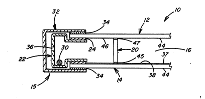
Fig. 1 is a plan view of a vacuum insulating unit
~! incorporating features of the invention.
Fig. 2 is a view taken along lines 2-2 of Fig. 1.
`~ 35 Fig. 3 is a view, similar to the view in Fig. 2,
illustrating an alternate embodiment of the edge assembly.1~ he
~; ' invcntion.
:
:.
..
, . .
~r
. ~ , I
. :
.'`'~
2~2~837
-- 3 --
Here described is a vacuum insulating unit having a pair of
sheets made of a fluid - e.g. gas-impervious material e.g. glass
sheets, a flexible, fluid - e.g. gas-impervious edge assembly to secure
the sheets together to provide a fluid - e.8. gas-impervious
compartment therebetween, and facilities e.g. supports in the
compartment to prevent the surfaces of the sheets from contacting one
another. The compartment has a negative pressure as compared to the
external pressure acting on the unit, i.e. a vacuum.
Also described is a method of fabricating the vacuum insulating
unit discussed above and include~, umong other things, the steps of
providing the pair of glass sheets, securing the edge assembly to the
glass sheets to provide the gas-impervious compartment therebetween,
and thereafter providing a vacuum in the compartment, while preventing
the sheets from contacting one another. In an embodiment of the
invention, supports to prevent the sheets from contacting one another
il are positioned between the sheets prior to securing the edge assembly
to the sheets.
Further described are supports of laminated layers of reinforced
i fibers impregnated with a thermoset or thermoplastic resin, e.g.
bismaleimide or polyamidimide.
Yet further described is a method of making the supports and
includes the steps of stacking sheets of resin impregnated fibers to
form a panel, curing the panel, and cutting the panel into supports.
The units are not limited to the fluid- e.g. gas-impervious value
of the sheets and/or the edge assembly; however, materials selected
are recommended to have values such that after the unit is assembled,
an absolute pressure of less than 10-5 torr is provided in the
compartment for a period of more than 24 hours. The units constructed
as described herein are expected to retaln the vacuum ln the
compartment for at least 10 years and up to 20 years.
~;~ DescrlDtion of the Preferred ~mbodlments
Referring to the drawing there is shown insulating unit 10 (Figs.
1 and 2) and 11 (Fig. 3) embodying the invention. In the following
~ discussion, unless indicated to the contrary, like numbers refer to- 35 like elements.
The unit 10 shown in Fi8s. 1 and 2 includes sheets 12 and 14 made
of a fluid- e.g. gas-impervious material secured together and spaced
from one another by a flexible fluid- e.g. gas-impervious edge assembly
.,
.,
: .
:.
"' ,,~
:
.~. .
. .
: 2~2~837
15 to provide a compartment 16 (see Fig. 2) therebetween. The
compartment 16 has a vacuum, i.e. a pressure less than the outside
pressure acting on the unit and has supports 20 to prevent the sheets
12 and 14 from bowing, or to minimize the bowing of the sheets, to keep
the sheets from contacting one another due to the external positive
pressure acting on the unit.
The sheets 12 and 14 and the edge assembly 15 provide a fluid
e.g. gas barrier to seal the compartment 16 from the environment to,
among other things, prevent the atmosphere outside the unit from moving
into the compartment thereby maintaining a pressure in the compartment
less than the pres~ure acting on the unit when in use i.e. maintains a
vacuum in the compartment 16.
The sheets 12 and 14 may be made of any fluid-impervious material
, ,:^,~
that has structural stability, e.g. glass, metal and/or a fluid
;~j15 perrious substrate haring a fluid-impervious material or film on its
surfaces.
. .
The term "fluid-impervious material" as used herein means a
`x~material that resists the flow of a fluid e.g. moisture or gas
A,~',therethrough. As will be appreciated the units 10 and 11 are
constructed of a plurality of components made of material~ that resist
the flow of fluids therethrough; however, the inrention is not limited
to components having a specific minimum fluid-impervious ralue. The
components when assembled provide a unit that has a sealed compart ent
in which a racuu level measured in absolute pressure can be maintained
for a predetermined period of time. Although, the components of the
unit are selected to resist the flow of gases that are constituents
having the proportions normal b present in air, the invention is not
limited thereto and contemplates the use of components to resist the
flow of any gas to aintain an absolute pressure in the compartment for
a specified time period. This feature is discussed in more detail
below.
The sheets 12 and 14, further, should have sufficient structural
stability either alone or in combination with the supports 20 to
prevent the sheets from contacting one another thereby preventing the
establishment of a thermal path through the unit. Maintaining the
sheets spaced from one another provides the units 10 and 11 with
.,,
thermal insulating properties. Although not limiting to the invention,
in the following discussion the sheets 12 and 14 are glass sheets.
~,
:",
:: `
.
.~
:
.~
~. .
2~25837
-- 5 --
The slze ana thickness of the glass sheets 12 and 14 are not
limiting to the invention; howe~er, the following should be considered
when selccting glass sheets. It has been shown that glass sheets 10
inches (25.4 centimeters) square and 1/2 inch (1.27 centimeters) thick
S separated by an edge retainer made of 1/8 inch (0.32 centimeter) thick
plastic frame placed inside a silicone rubber 0 ring positioned at
marginal edges of the sheets bowed, but the ~hects did not contact one
another when a ~acuum of 10-5 torr was pulled in the com~artment
between the sheets. It is e~ected that increasing the ~eripheral
dimensions of the sheets while maintaining the sheet thickness and
vacuum le~el constant, would increase the degree of bowing of the
sheets, i.e. decrease the distance betwéen the sheets, and ~isa versa.
Further, it is also expected that decreasing the sheet thickness while
maintaining the ~eripheral-dimensions of the sheets and the ~acuum
level in the space between the sheets constant would increase the
degree of bowing and ~isa ~ersa.
Thé degree of bowing of the sheets may be minimized by using
substantially rigid glass sheets, as discussed abo~e, using sheets
ha~ing a con~es surfacc i.e. the sheets bow outwardly, or using
supports between the sheets e.g. si~ilar to the su~orts 20 shown in
the drawing. The use of the supports 20 to reduce the degree of sheet
bowing is preferred because uslng supports permits the peripheral
dlmension~ of the sheets to lncrease a~d their thlckness to decrease
whlle minimizing sheet bowing. This results in reduced overall weight
of the unit when compared to a unit made of substantially thicker rigid
sheets.
Because the compartment 16 will be under a negatlve pressure, it
is recommended that ~re-stresset e.g. heat strengthenet or tempered
glass sheets be used to ellm~nate the ~ro~enslty of sheet breakage.
The sheets may be pre-stresset ln any con~enlent manner e.g. as taught
ln U.S. Patent ~o. 3,174,839.
The glass ~heets 12 ant 14 may be clear, tinted, coated or any
combination thereof. For esam~le, one of the sheets may have an
en~ironmental coating such as the ty~es dlsclosed in U.S. Patent Nos.
2,566,346; 3,447,g36; 3,660,061; 4,594,137; 4,6g2,389; 4,610,771
or in U.S. Patent 4,898,790 in the name of James Finley ant entitled
"Low Emi~si~ity Film For High Temperature Processing~.
.,
.,
. ~,
.
;,~,
.... .
,.... . .
:
- 202~837
-- 6 --
~8 will be dlscussed in detall below, during the assembly of the unlt
10, the sheets wlll be esposed to elevated temperatures; therefore,
; the coating aelected should be capable of wlthstandlng ele~ated
~ temperatures wlthout deterloratlon thereof. Coatlngs that may be used,
but not limlted thereto, are those taught ln the above ~entloned U.S.
Patent ~o-. 3,660,061 and 4,610,771 and ln the U.S. patent application.
Beferring back to Figs. 1 and 2 and as pre~iously mentioned, the
glass sheets 12 and 14 are maintained ln spaced relation by the
supports 20. The shape, size, nu~ber, and the properties and
composition of the material of the supports i8 not limiting to the
in~ention; however, in identifying oupports for use in the apparatus,
the follo~lng should be considered.
The shape of the su~orts 20 i8 preferably selected to minimize
stresses in the glass caused by the support contacting the glass.
It has been concluded that supports made of materials that have
high elastlc modulus e.g. glass, steels or aluminu~ establlsh hlgh
stresses near the interface in the glass sheets and are not
preferred. ~ore partlcularly, use of materlals that have a high
elastlc modulus regulre preclslon machlnlng of a contact surface
and holght for unlform load sharlng and d nlmal contact stresses.
Supports ha~ing some degree of compressibility i.e. relatlvely low
elastlc modulus are preferably used. Further supports having a
;
: ,
. ~
,i
.,
_ 7 _ 2~2~37
planar supporting surface e.g. but not limited to columns having
circular, parallelepiped or triangular cross sections are recommended
because there are minimal and uniform contact stresses at the
sheet-support interface. It is further preferred to employ supports
5 that have a circular cross section because their shear flexibility is
not preferential with respect to direction, and stress concentration at
the corner is absent when the sheets and supports move relative to one
j another as a result of temperature differences between the sheets 12 and
-~ 14 and/or the edge assembly 15.
The ~ize, strength and number of the supports should be
selected to support the load transmitted through the sheets to
prevent the sheets from contacting one another while having minimal
,:
contributlon to increasing thermal conduction through the unit and
minimal reduction in the viewing area of the unit. As can be
15 appreciated increasing the number of supports minimizes the de8ree of
bowing of the sheets; however, too many supports can establish paths
of thermal conduction through the unit thereby reducing its
lnsulating value and can ~180 obstruct viewing through the unit.
Increasing the size of the supports while maintaining the other
20 characteristics of the supports constant decreases the required
number of supports; however, increasing the size makes the supports
more noticeable. Increasing the load carrying capacity of the
supports reduces the number of supports reguired to prevent the
sheets from contacting one another and increases the viewing area of
25 the unit. As can be appreciated visual observation of the supports
;;~ is a sub~ective test and is not limiting to the invention; however,
;~ the size and number of support used to prevent the sheets from
contacting one another should be such as to provide maximum viewing
and minimum sheet bowing.
The material composition for the supports is selected to
permit minimal thermal conduction through the sheets, to have minimal
i~ if any outg~ssing products for reasons which are discussed in more detail below and to have structural stability. By way of
illustration, plastic spacers are preferred over metal spacers
~ 35 because plastic materials are generally lower heat conductors.
: Another mechanlcal property to be considered in selecting material~
.~
. ~
.~,.' .
...
o~
.~ .
.,
,:
. . .
. . .
- 8 - 2~2~837
for supports i8 elastic strain. Supports made by materials that
elastically deform to ad~ust to the glass surface when under
compression are preferret.
As previously mentioned the glass sheets may move relative
S to one another due to thermal differences of the ~heets. When this
joccurs, the relative spaced distance between the supports may change
during such sheet movement. Although both ends of the supports can be
adhered to the surfaces of the glass sheets facing the compartment,
excessive movement of the glass sheets may result in shearing of the
~,10 supports and/or marring of the glass surfaces. Therefore, the preferred
embodiment is to adhere one surface of the support to a glass sheet and
provide a material having a low coefficient of friction on the other
end. Materials that are preferred are those that have a low coefficient
~,of friction in vacuum, for example, but not limiting to the invention,
15 molybdenum disulfide and materials sold under the trademark Tcflon.
Supports that may be used in the practice of the invention
may be made by impregnating a thermosetting material e.g.
bismaleimide, epoxy, cyanate eitherimide, or combinations thereof or
a thermoplastic material e.g. polyamidimide into a fabric or mesh
20 screen e.g. fiberglass tape, coverings or fabrics and laminating the
fabrics to obtain the desired height for the supports. An adhesive
may be provided at one end of the support to prevent movement of the
support and a low friction material at the other end e.g. Teflon~
powder, molybdenum disulfide powder or vacuum sputtered molybdenum
25 disulfide. Materials such as carbon black may also be used for
colorization, W stability and resin or matrix strength.
With reference to Flg. 2, the flexible edge assembly 15
includes a fluid-, e.g. gas-impervious edge retainer 22 adhered to
the glass sheets by a fluid-, e.g. gas-impervious sealant adhesive 24
30 to prevent the atmosphere from moving into the compartment 16. The
edge assembly 15 is preferably flexible to allow the glass sheets to
move relative to one another due to thermal differences of the sheets
and/or the edge a~sembly. To minimize stress due to expansion
mismatch, but not limiting to the invention, it is recommended that
~l35 the materials of the sheets, edge retainer and sealant adhesive have
-similar coefficients of expansion. Further, the edge retainer should
, .
$
:.
. .
,~
.
...
_ 9 _ 2025837
be made 90 that it can flex to accommodate thermal differences
between the sheets. In Fig. 2 the edge retainer 22 is shown to have
a hair pin cross section, and in Fig. 3 edge retainer 26 of flexible
fluid- e.B. gas-impervious edge assembly 28 has a C-shaped cros~
i 5 section.
The edge retainer 22 is preferably made of metal; however,
other fluid-impervious materials or fluid-pervious materials having
~ fluid-impervious coating or film over the surfaces may be used in the
:~ practice of the invention.
Any type of fluid-impervious sealant adhesive 24 may be used
to secure the edge retainer 22 to the glass sheets. For example and
not limiting to the invention, a metal edge retainer may be secured
to the marginal edges of the glass sheets by a sealant adhesive of
the type sold by Ferro Corporation as EJ-179.
'~i, 15 In those instances where the sealant adhesive is a frit and
is used with a metal edge retainer, the surface of the edge retainer
should be prepared to improve adhesion between the frit and edge
retainer. Aluninum doped metals are easily oxidized whereas metals
that do not readily form an oxide layer on its surface may require
20 special process to oxidize the surface. For example, an edge
retainer made of an alloy having 53% iron and 47% nickel used with
; Ferro's EJ-179 sealant adhesive is oxidized by heating the edge
retainer to a temperature of about 1700F (927C) in a C02 steam
~i atmosphere for a period of about 65 minutes. The atmosphere during
25 heat up was a forming gas and on cool down was nitrogen.
1 In instances where the sealant adhesive has to be heat setj or heat activated, the surfaces of the components of the unit e.g.
the supports 20 will outgas; further surface outgassing of the
~ components may occur during use of the units 10 and 11. To adsorb
; 30 the outgassed products, it is recommended that a getter 30 such as
the type sold by SAES Getters # ST707 be in communication with the
compartment.
With continued reference to Fig. 2, a protective cover 32 is
secured around the perimeter of the unit 10. The cover 32 is made of
35 a plastic material e.g. polyvinyl chloride and is adhered to the
outer marginal edge of the unit 10 in any convenient manner, e.g. by
a hot melt adhesive layer 34.
.. , I
,.j
~,
- 2~25837
Vacuun may be pulled in the compartment 16 through a hole 36
in the retainer 22 or 26 or a hole (not shown) in one of the glass
sheets. After the vacuum is pulled the hole is sealed in any
- convenient manner.
3 5 In those instances where the setting or activating
;; temperature of the sealant adhesive 24 is higher than the
decomposition temperature of the supports 20 and lower than the
melting temperature of the sheets, the ~ealant adhesive 24 may be set
to ~oin the edge retainer and the sheets together by preferential
10 heating e.g. heating with a laser or passing current through the
metal edge retainer. In those instances where the setting
temperature of the sealant adhesive is lower than the temperature at
which the sheets and supports lose their structural integrity, the
components of the unit may be assembled and heated in an oven at a
15 temperature above the settin8 temperature of the sealant adhesive and
below the temperature at which the supports or any other component of
the unit lose their structural integrity.
In the discussion of the glass sheets 12 and 14 and edge
assemblies 15 and 28, the term fluid- or gas-impervious was used to
20 describe a characteristic of the material. The sealed compartment 16
defined by the glass sheets and the edge retainer 22 or 26 has a
negative pressure in relationship to the pressure outside the
compartment i.e. a vacuum is provided in the compartment 16. To
maintain the compartment under negative pressure is a functlon of the
;; 25 fluid-impervious properties of the sheet and edge assembly;
therefore, each component of the ed8e assembly, and the sheets are
selected to cooperate with one another to prevent a fluid such as air
1 from penetratln8 into the compartment. For example, lncreasing the
thickness of a ~ealant adhesive layer having a hlghet gas
30 permeability than the glas~ sheets and metal edge retainer will
prevent air from moving into the compartment better than a thicker
-i layer of the same adhesive. Therefore, as used herein the terms
"fluid impervious" or "gas impervious" are descriptive of the
components acting together after they have been assembled to form the
; 35 unit 10 or 11. A unit capable of maintaining an absolute pressure in the
compartment of less than 1.0 torr for 24 hours is made of components
".~
~,:`,:j
.~
:i
.,
,i.
., .
,i,:
11 202~837
having adequate fluid- or gas-impervious values; units capable of
saintaining an absolute pressure in the compartsent of less than 10-4
torr for 24 hours is for purposes of the invention sade of components
having acceptable fluid- or gas-ispervious values, and units capable of
saintainin8 a vacuu~ of less than about 10-6 torr for 24 hours is
considered to be ~ade of cosponents having optisus fluid- or
gas-i pervious values. In each of the foregoing the spacing between
the sheet surfaces facing the cospattsent is about 0.020 inch (0.0508
centi~eter). Although the ti~e period is 24 hours it is espected that
10 units ~ade as here described can retain the vacuu~ in the cospartsent
for at least 10 year~ with an expected period of up to 20 years.
The pressure in the cospartsent ~ay be easured ln any convenient
~anner. For esasple but not lisiting to the invention, the unit under
test is placed in an evacuated chasber having a known absolute
15 pressure. The edge as~e~bly or the sheet has a hole drilled and the
absolute pressure ~alue in the cha~ber observed. In those instances
when the atsosphere in the cospartsent of the unit ~oves into the
chasber, i.e. the pressure in the co~partsent is greater than the
pressure in the chasber the absolute pressure in the chamber
20 lncreases. In those instances when the atmosphere in the chamber soves
into the co~partsent, i.e. the pressure in the cospartsent is less than
the pressure in the cha~ber, the absolute pressure in the chasber
decreases.
As can now be appreciated by those s~illed in the art other tests
s 25 say be used to detersine the absolute pressure in the compartment.
Although prototypes of the invention have been sade to evaluate
the various components of the unit, ln the followlng dlscusslon, unlts
are constructed based on the knowledge obtained fros evaluating the
prototypes.
The units 10 and 11 shown in Fi8s. 1-3 ~ay bo constructed ln the
following ~anner. Glass sheets 12 and 14 each ha~ing dimensions of 20
inches (50.8 centiseters) X 14 inches (35.56 centlseters) X 0.09 inch
(0.23 centi~eter) are thermally tespered and thereafter a low
emissivity heatable coating 37 is either sputtered or
!,1
,i,;, .
~, I
.~' .,
.' L~
,, : - ~
- 12 - 2025837
pyrolytically applied to one surface of a sheet e.g. surface 38 of
the sheet 14.
In the first example, the unit shown in Fig. 3 will be
constructed. The supports 20 used in the example have a
5 decomposition temperature less than, and the glass sheet~ have a
decomposition temperature higher than, the setting temperature of the
sealant adhesive 24 of the edge assembly 28.
The C-shaped edge retainer 26 made of an
~; iron-nickel-aluminum alloy and having a thickness of 0.003 inch
10 (0.00762 centimeters) is cut into two sections each having an "L"
shaped cross section. The sections are oxidized. Since the alloy
has aluminum, any convenient oxidizing technique may be used. The
'~ L-shaped sections are welded at their ends to provide a fluid
i~ impervious frame section. Ferro Corporation frit EJ-179 324 is
15 extruded onto the marginal edges of outer surface 42 of the glass
; sheet 12 and uncoated or outer surface 44 of the glass sheet 14. One
,~ frame section is mounted on the adhesive layer 24 on the outer
marginal edges of the sheet surface 42, and the other frame section
mounted on the adhesive layer 24 on the glass sheet surface 44. The
20 subassemblies are heated to about 800F (427C) to set the adhesive
layer 24 and secure the frame sections to their respective sheets.
A bismaleimide support 20 is prepared as follows.
Bismaleimide and carbon black are impregnated into a fiberglass woven
-~1 fabric to produce prepregs having a t~ickness of about o.ob4 inch
25 (0.0102 centimeter). "Prepregs" as used herein means a substrate
' e.g. fabric or mesh impregnated primarily with a thermoplastic or
- thermosetting resin. The prepregs are layed in alternating
~~ directions to minimize internal stress and layed to a thickness
sufficient to provide a thickness of 0.020 inch (0.0508 centimeter)
30 after the layered prepregs are curet. A film made of a Teflon~
powder dispersed into a bismaleimide film is positioned on top of the
layed-up prepregs. The layed-up prepregs are placed in an autoclave
~; and heated to a temperature of about 350F (176C) for about six
hours at a pressure of 85 psi to cure and laminate the layed-up
~; 35 prepregs to form a panel of a thickness of about 0.020 inch (0.0508
~; centimeter). The panel is then post-cured in an oven at a
temperature of about 450F (232C) for six hours. An adhesive 47 is
. .
-:,
~,.,;
.,
i
.:.
~.~
:;~
.~
- 13 - 202~837
applied to the panel surface opposite to the surface having the
Teflon~ powder. The surface of the panel having the adhesive is
: placed on a low-tack adhesive tape, and the panel diced into cubeshave a side length of about 0.020 inch (0.0508 centimeter). The
5 cubic shaped supports are removed from the tape, and the surface
having the adhesive adhered to a glass sheet.
The spacers are secured to inner surface 46 of the glass
i sheet 12 by the adhesive 47. The spacers 20 are on a center to
center spacing of about 0.725 inch.(1.84 centimeter). The upper and
10 lower glass sheets are brought together about the supports and the
frame sections are welded together in any convenient manner. The
hole 36 is provided in the edge retainer 26, and the unit is heated
3 in an oven to a temperature of about 600F (315C) to outgas the
components e.g. supports of the unit. As the unit is heated, a
15 vacuum is pulled through the hole to provide a vacuum level of 10-5
torr in the compartment 16 as an activated getter 30 of the type sold
by SAES Getters is moved through the hole 36 into the compartment
16. After an absolute pressure level of about 10-5 torr is reached,
~J the hole 36 is conveniently sealed e.g. welded shut. Thereafter the
20 unit 10 is further heated for one hour at a temperature of 400F
(204C) to further outgas the components. The outgassing product is
adsorbed by the getter 30.
In the second example the construction of the unit 10 shown
in Fig. 2 will be discussed. In this example, the adhesive layer 34
25 has a setting temperature lower than the decomposition temperature of
the supports 20, i.e. lower than 600F (315C) and the glass sheets.
After the glass sheet surface 38 is coated and the supports
20 secured to the glass sheet surface 46 by the adhesive layer 47,
the layer of sealant adhesive 24 is applied to the inner marginal
30 edges of the glass sheets 12 and 14 as viewed in Flg. 2. Sections of
the edge retainer 22 having the hairpin cross section have their ends
welded to form a gas-impervious frame and thereafter the frame is
oxidized. A layer of the sealant adhesive is also applied to the
outer surface of the frame and the frame ends positioned between the
35 sheets while the sheets are clamped together about the supports. The
c assembly is heated to a temperature below the decomposition
temperature of the supports e.g. below 600F (325C) and above the
~j1
.~ . .
- 14 _ 2~5~37
- setting temperature of the adhesive sealant to set the adhesivesealant and outgas the components. After sealing, the temperature is
dropped to 400-F (204C), a vacuum level of 10-5 torr is pullea
,' through the hole 36 in the frame; the getter 30 is inserted through5 the hole 42 into the compartment 16, and the hole sealed. The unit
3 is further heated at 400F (204C) for about one (1) hour to further
or completely outgas the components.
3 After the unit has cooled, the protective cover 32 is
positioned around the marginal edges of the unit and secured to the
10 outer ~arginal edges of the glass sheets 12 and 14 as viewed in Fig.
2 by the hot melt adhesive layer 34.
In the third examyle a unit o~ the type shown in Fig. 3 is
constructed using the adhesive layer 34 having a setting temperature
lower than the decomposltion temperature of the supports 20, i.e.
15 lower than 600-F (315-C) and the glass sheets.
The procedure discussed in the second example is practiced
except the ed8e retainer 26 instead of the edge retainer 22 is used.
After the supports are positloned between the glass sheets a pair of
U-shaped sectlons each havlng a "C" shaped cross seetion is
20 positioned over the marginal edges of the glass sheets having the
spacers therebetween. The ends of the U-shaped sectlons are ~olned
together e.g. by weldlng, and an adheslve 18 extruded between the
edge retalner and the glass sheets to provlde the adheslve layer 24
~ as shown ln Flg. 3.
3 25 The assembly 18 then heated as discussed in the second unlt
to provlde the novel vacuum lnsulatlng unit.
Units constructed ln accordance with the above teachings are
expected to maintaln an bsolute pressure level of about 10-5 torr
for about 20 years. The R value 18 between 6-10 ln dlmensions of
30 hour-feet squared--F per BTU.
~i As can now be appreclated the lnventlon 18 not llmited to
j~ any of the preceting discussions nor to the embodiments and examples
x which are presented for illustration purposes only.
A
~"'
'X
'
.,
`~.
.~, .