Note: Descriptions are shown in the official language in which they were submitted.
202~8~4
EQUIPMENT RACK
The invention pertains to equipment racks.
Prior art equipment racks will be discussed hereinbelow in
conjunction with drawings.
S The invention involves a rack ha<ring a configuration which achieves
physical separation between different types of cables and/or between functionally
different cables of the same type, without the use of hazardous cable brackets.
In addition, the inventive rack protects cables against inadvertent damage by
operating personnel, is height extendible, and is relatively light and thus relatively
easy to install.
In accordance with one aspect of the invention there is provided
apparatus for holding electronic equiprnent comprising: a first frame member,
generally U-shaped in cross section, including a first pair oE arms and first
¦ enclosing means connected to said first pair of arms, for partially enclosing at
least a portion of the space between said first pair of arms, whereby a first
partially enclosed channel is formed between said first pair of arms; a second
frame member, generally U-shaped in cross section, including a second pair of
arms; connecting means for connecting at least one pair of ends of said frame
members to each other; and first bundling means positioned in said first channel,
for bundling cables.
The inventive rack is similar to the conventional channel and
duct-type relay racks in that it includes two Erame members that are generally
U-shaped in cross section, with the arms of each generally U-shaped frame
member being apertured and either pointing toward or away from the arms of
the other generally U-shaped framo member. However, and by contrast with the
convontional relay racks, tho inventive rack includes additional structures
connected to, and extending from, the arms of at least one frame member, which
serve to partially enclose the space between these arms. For example, if the
arms of the &ame members of the inventive rack point toward each other (as in
a conventional channel relay rack), then each of the arms of at least one of thegenerally U-shaped frame members of the inventive rack includes a protrusion
.
~ along its inner surface. On the other hand, if the arms of the frame members of
:4
., . ,~ . . . .
: ~: :.
, .: , ~ ~` , : i
:: :` "
202~4
-2-
the inventive rack point away from ~ach other (as in a conventional duct-type
relay rack), then the relatively wide arm oE at least one of the frame members
includes a protrusion along its inner surface, while the corresponding relatively
narrow arm includes a flange extending from the edge of the arm. The two
S protrusions, or protrusion and flange, in conjunction with other portions of the
corresponding frame member, selve to partially enclose the space between the
arms, and thereby define a channel into which a device, here termed a cable
restraint device, is readily inserted (through the space between the protrusions or
protrusion and flange), and wedged. In a preferred embodiment, each such
cable restraint device includes one or more physically separated loops, connected
to the upper surface of the device, which project through the space between the
protrusions or protrusion and flange. A strip of material, e.g., a nylon strip, is
connected to each loop. In use, different types Oe cables and/or ~unctionally
different cables of the same type are extended vertically downwardly between
the arms of the generally U-shaped frame member, and the material strips
connected to the physically separated loops are used to separately bundle the
cables according to type and/or Eunction. In addition, all the cables are encircled
by the arms and other portions of the generally U-shaped frame member, and
are thus protected against inadvertent damage by operating personnel.
Significantly, the inventive rack is either of a fL~ed height, or is
height extendible. That is, in the former case, the generally U-shaped frame
members are manufactured to have a specified height, and cross members are
connected to the tops and bottoms of the frame members. In the latter case,
there is no cross member connecting the tops of the generally U-shaped frame
members. Rather, the inventive rack includes two additional, generally U-shaped
frame members (the movable frame members), each of which is sufficiently
narrow so as to ft between the arms of one of the above-described generally
U-shaped frame members (the stationary Erame members). In addition, each of
the movable frame members includes an indentation along the outer surface oE
one or both of its arms, which indentation receives a corresyonding protrusion
along the inner surface of an arm of the stationary frame member, the
protrusion here serving as a keyway along which the movable Erame member
slides telescopically between the arms oE the stationary frame member. By
A
!
',''. : . ' , ' ,, ' ` "'
. ~ ' ~ ,
' ' ' ' . : ,. :
'i ` ' ' " :'
" ~ J
. .
3 2~2~
forming apertures in the arms of the movable frame members which correspond
to the apertures in the arms of the stationary frame members, the movable
frame members are, in use, telescoped to a desired height, and bolts or screws
are readily extended through aligned apertures in the arms of the movable and
- 5 stationa~y frame members to achieve a rack having any of a wide variety of
heights.
Preferably, the arms of at least one of the movable frame members
are fabricated to include protrusions, or a protrusion and a flange, which againdefne a channel into which a cable restraint device, of the type described above,
is readily inserted and wedged. Thus, the height-extendible version of the
inventive rack also achi~ves the advantages oE the non-extendible version, i.e.,different types of cables, as well as the same types of cables serving differentfunctions, are also readily separately bundled (with the aid of the cable restraint
device) and therefore physically separated. In addition, all the cables are
lS enclosed by the arms and other portions of the movable frame member, andconsequently all the cables are protected against inadvertent damage by
operating personnel.
The inventive rack is preferably of aluminum, which is almost as
strong as, but much lighter than, steel. As a result, the inventive rack is
essentially as sturdy as the previously used steel racks, but much lighter and thus
much easier to install than the previously used steel racks. Moreover, aluminum
is readily extruded into the relatively complex shapes associated with the
invention, e.g., generally U-shaped frame members with protrusions, which is
presently not possible with, for example, steel.
Brief Description of the Drawinys
The invention is described with reference to the accompanying
drawings, wherein:
FIG. 1 depicts a conventional channel relay rack;
FIG. 2 depicts a conventional duct-type relay rack;
FIGs. 3 and 7 depict, respectively, first and second, fixed-height
embodiments of the inventive rack;
.,
.
, ~ , , .
: ~ ,
~. ~ ''. -
202~8~4
FIG. 4 is an expanded view of a portion of the first embodiment of
the inventive rack, depicting use of a first, preferred embodiment of the
inventive cable restraint device;
FIGs. 5 and 6 depict, respectively, the first, preferred embodiment,
5 and the second embodiment, of the inventive cable restraint device;
FIGs. 8 and 10 depict, respectively, third and fourth, height
extendible embodiments of the inventive rack; Figure 10 is located on drawing
sheet 9/10.
~ IG. 9 is an expanded view of a portion of the third (height
10 extendible) embodiment of the inventive rack, depicting use of the preferred
embodiment of the cable restraint device;
FIG. 11 is a cross-sectional view oE the fourth (height extendible)
embodiment of the inventive rack, depicted in FIG. 10; Figures 9 and 11 are
located together on drawing sheet 8/10.
FlGs. 12 and 13 depict an extendible guardrail, preferably included
with the inventive rack; Figures 12 and 13 are located together on drawing
sheet 10/10.
A rack, as used in this disclosure, denotes a frame-like structure
adapted to hold and display equipment, such as electronic equipment. Such
20 racks are employed in a variety of settings including, for example, the central
offices of telephone companies and hospital operating rooms.
In the past, the racks employed in, for example, telephone company
central offices were used to hold the electromechanical relays employed in
switching telephone calls between subscribers. Although switching is now
25 typically achieved electronically, and the racks employed by the telephone
companies are now more generally used to hold electronic equipment, including
electronic telephone switching and electronic telephone transmission equipment,
these racks are still often reEerred to as relay racks.
At present, the (relay) racks employed by the telephone companies
30 are typically of two types. The first type, depicted in FIG. 1, is generally
referred to as a channel relay rack, and conventionally includes generally parallel
(in use, generally verticalb oriented) steel frame members 10 and 20, which are
~,,~, : ... ...... .
. . :.. , : . :, ;., . . ............... -
. .- . .
2~2~8~l~
- 5 -
U-shaped in cross section. The arms 11, 12, 21 and 22 (see FIG. 1) oE these
U-shaped frame members are apertured at regular intervals along their lengths,
with the arms of one U-shaped frame member pointing toward the arms of the
other U-~haped frame member. An angle iron 30 and an apparatus 60, which
5 are welded or bolted to, respectively, the tops and bottoms o~ the U-shaped
~ame members, serve to connect the U-shaped members. In addition, the
apparatus 60, often referred to as a guardrail, serves to prevent equipment
mounted in the relay rack &om being struck by the ladders used by operating
personnel to inspect the equipment. That is, as shown in FIG. 1, the guardrail
60 includes two members 40 and 45 which, in cross section, have inverted
~shapes. The inverted L,shaped members 40 and 45 are connected to the
bottoms, and extend between, the U-shaped frame members 10 and 20. A
rectangular, sheet-like member S0, positioned between the U-shaped frame
members 10 and 20, is connected to the inverted L-shaped members 40 and 45
15 via screws or bolts, and thus serves to connect the members 40 and 45 to eachother. As is evident, the protruding flanges of the inverted L-shaped members
40 and 45 extend by a fL~ed distance from the front and back of the channel
relay rack, and thus serve to deflect ladders from striking the equipment.
Significantly, the U-shaped frame members 10 and 20 are
20 conventionally manufactured in four different heights, i.e., 7 feet (2.13 meters),
9 feet (2.74 meters), 10~/2 feet (3.20 meters) and 111/2 feet (3.50 meters). As a
consequence, the conventional channel relay rack is typically only available in
four (corresponding) different heights.
Equipment is mounted in the conventional channel relay rack by
25 initially attaching laterally projecting flanges to the front or back of the
equipment. Then, the equipment is inserted between the frame members 10 and
20 until the laterally projecting flanges are flush with the arms of the ~rame
members 10 and 20, and screws or bolts are inserted through apertures in the
flanges aligned with apertures in the frame member arms. It must be noted that
30 the equipment is mounted either before or after the rack is sold. That is, inmany instances, equipment, such as the electronic equipment employed in
telephonic signal switching or telephonic signal transmission, is mounted in the
A
.
,
2~8~
- 6 -
rack immediately after rack manufacture, and the equipment-filled rack is sold as
an integral unit. Alternatively, the rack is sold empty of equipment, and
equipment is mounted in the rack by the purchaser.
After a rack is sold (either with or without equipment) and
S installed, equipment mounted in the rack is typically examined and/or accessed
with the aid of ladders. As discussed, the guardrail 60 serves to prevent the
ladders ~om hitting the equipment.
In, for example, telephone company central offices, electrical power
is delivered to equipment mounted in a charmel relay rack through power cables
extending from an overhead, generally horizontally positioned, ladder-like cablerack. Similarly, electrical signals are transmitted from, and received by, the
equipment through transmission cables also extending from an overhead cable
rack (different &om that used for the power cables). In addition, in many
instances, special purpose alarm cables are provided, extending from yet anotheroverhead cable rack to the equipment, and from the equipment to remote alarm
equipment in the telephone company central office, the alarm cables serving to
communicate signals from the equipment to the remote alarm equipment
indicative oE equipment malfunctions. Significantly, further physical separationbetween the transmission cables and the power cables, beyond that achieved
through the use of different cable racks, is needed to avoid creating spurious
r electrical signals in the transmission cables due to electrical noise in the power
cables (the alarm cables are generally insensitive to such noise). This additional
separation is achieved in a conventional channel relay rack, as shown in FIG. 1,~, through the use oE right-angle steel brackets 70 and 80, generally referred to as
cable brackets, bolted to the back oE the relay rack. That is, in operation, thepower and alarm cables are extended vertically downwardly Erom their respective
overhead cable racks and positioned within, or immediately adjacent to, the
corner formed by the arms oE the cable bracket 70, Erom which they are further
extended vertically and then horizontally into electrical contaot with the mounted
equipment. On the other hand, the transmission cables are also extended
verticalb downwardly from their overhead cable rack, but these cables are
positioned within, or immediately adjacent to, the corner formed by the arms oE
~ A
.
.
- 2~2~8~
- 7 -
the cable bracket 80, from which they are further extended vertically and then
horizontally into electrical contact with the mounted equipment. As a result, the
transmission cables are always spaced apart from the power cables.
While the conventional channel relay rack is useful, it does have
several disadvantages. For example, the power, alarm and transmission cables
are positioned outside of (rather than between) the arms of the U-shaped frame
members 10 and 20, and thus these cables are exposed to inadvertent contact,
and resulting damage, by operating personnel and passersby. In addition, it is
often desirable to further separate the transmission cables according to function,
i.e., according to whether the cables are used to transmit electrical signals to, or
from, the mounted equipment, in order to avoid cross talk between the
functionally different cables. However, this is not possible with a conventionalchannel relay rack because the cable brackets included in such racks serve to
achieve nothing more than the physical separation of transmission cables
(regardless of function) from power and alarm cables. Further, because the
cable brackets 70 and 80 protrude from the relay rack, and are of steel, they
represent a safety hazard to operating personnel. Additionally, because the
conventional channel relay rack is entirely of steel, it is heavy and therefore
difficult to install, whether or not filled with equipment, because much of the
weight of a conventional, filled channel relay rack is attributable to the weight of
the steel frame members. Moreover, because the conventional channel relay
rack is not extendible (in terms of height), it is generally necessary to stock all
four sizes of the relay rack, which increases shipping costs and often necessitates
the use of a relatively large amount of limited, and thus expensive, storage space.
The second type of relay rack employed by the telephone
companies is depicted in FIG. 2 and is generally referred to as a duct-type relay
rack. As shown in FIG. 2, a conventional duct-type relay rack is similar to a
conventional channel relay rack in that it includes two generally parallel (in
use, generally vertically oriented) steel frame members 110 and 120 which are
U-shaped in cross section and have arms which are apertured. However, by
contrast with the conventional channel relay rack, the arms 111 and 112 of the
frame member 110 point away from the arms 121 and 122 of the frame member
120. In addition, the arms 112 and 122 have identical widths which are smaller
',,,.
.. , .............. .
.
:: , ' ' . ' '
;
,
:, ' , .
,
2~2~8~4
- 8 -
than the identical widths of the arms 111 and 121. In all other respects, the
conventional duct-type relay rack is generally structurally similar to the
conventional channel relay rack. That is, the conventional duct-type relay rack
further includes steel cross members 130 and 140 connected to, respectively, thetops and bottoms of the U-shaped frame members 110 and 120, as well as a
steel guardrail 160 (oe the type pictured in FIG. 2) projecting
(by a ~xed distance) from the bottom of the duct-type relay rack.
In use, the conventional duct-type relay racks are often placed very
close to one another, and thus the relatively wide arms 111 and 121 (see FIG. 2)of the U-shaped frame members of one relay rack often project into contact, or
into close proximity, with the corresponding arms of the U-shaped frame
members o~ adjacent duct-type relay racks. Moreover, any inteIvening space
between the adjacent, relatively wide arms is often covered, at least in part, by a
plate. As a consequence, two substantially enclosed, vertical ducts (hence the
name of the relay rack) are Eormed on the opposite sides of each duct-type relayrack. In addition, the smaller widths of the frame member arms 112 and 122
(see FIG. 2) results in a gap between the arm 112 of one rack and the arm 122
oE an adjoining rack, thus permitting access to the rear of the vertical duct
formed by the arms of the two racks. Significantly, in use, the power and alarm
cables are extended vertically downwardly into one such (substantially enclosed)vertical duct, the transmission cables are extended vertically downwardly into the
other such vertical duct, and both sets of cables are then extended horizontally(out through the gaps in the vertical ducts) into electrical contact with the
mounted equipment. Thus, this rack configuration is advantageous because,
while the power and transmission cables are physically separated, all the cablesare largely enclosed by the arms of adjacent U-shaped frame members, and
therefore protected against inadvertent damage by operating personnel.
Although the convcntional duct-type relay rack has a configuration
which prevents inadvertent damage to power, alarm and transmission cables by
operating personnel, it, like the conventional channel relay rack, is incapable of
achieving physical separation between functionally different transmission cables,
i.e., between the transmission cables used to transmit, and receive, electrical
signals. The conventional duct-type relay rack is also entirely of steel, and thus
. ., . ~ ,,
:
2~2~8~
- 8a -
heavy and difficult to install. In addition, like the conventional channel relayrack, the duct-type relay rack is not extendible (in terms of height), i.e., it is only
manufactured in the four different sizes, given above. Because all four sizes
must generally be stocked, the use of the conventional duct-type relay rack alsoS involves high shipping costs and also requires the use of a relatively large amount
of limited, and therefore expensive, storage space.
~i Thus, those engaged in the development of equipment racks have
sought rack configurations which achieve physical separation between different
types of cables, such as power and transmission cables, as well as between
10 functionally different cables of the same type, such as transmission cables used
for transmitting, and receiving, electrical signals, without the use of hazardous
(to operating personnel) cable brackets. In addition, and equally importantly,
those engaged in the development oE equipment racks have also sought rack
configurations which prevent inadvertent damage to cables, are height
15 extendible, and are relatively light and therefore relatively easy to install.
The invention involves an equipment rack which achieves physical
separation of cables according to type and/or function without the use of cable
brackets, while protecting the cables from inadvertent damage by operating
personnel. In addition, some embodiments of the rack are height extendible,
20 thus obviating the need to buy, ship and store different sized fixed-height racks.
Further, the rack is preferably of aluminum, and is therefore relatively light and
easy to install.
As discussed, the inventive rack includes at least two frarne
members, generally U shaped in cross section, having arms which either point
25 toward each other, as in the conventional channel relay rack, or point away from
each other, as in the conventional duct-type relay rack. However, by contrast
with the conventional relay racks, the arms oE at least one of the frame membersOe the inventive rack include protrusions or a protrusion and a flange which
serve either of two functions. That is, if the inventive rack is, for example, of a
30 fLxed height, then the protNsions, or the protrusion and flange, in conjunction
with other portions of the frame member, serve to partially enclose the space
between the arms of the frame member, and thereby define a channel capable
.... .
'
~' ', '~
';` ' ' ~'
.' ' '
202~8~4
- 8b-
of receiving a cable restraint device. On the other hand, if the rack is height
extendible, then the protrusions serve as keyways which allow movable frame
members to slide telescopically between the arms of stationary frame members.
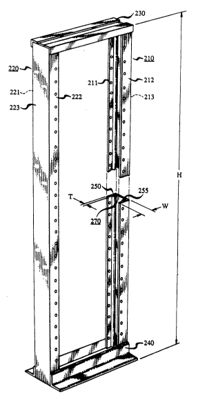
With reference to FIG. 3, a first fixed-height embodiment of the
S inventive rack includes a first frame member 210, generally U-shaped in cross
section, and a second frame member 220, also generally U-shaped in cross
section. (To determine whether a frame member, when viewed in cross section,
is generally U-shaped for purposes of the invention, identify the midpoint of the
intersection of the arms of the frame member, i.e., where the arms are physically
10 joined to create a
._~, .
:: .
2Q2~8~
frame member, and then draw a first straight line from this midpoint to the end of the
i first ann and a second straight line from the midpoint to the end of the second arm.
To be considered generally U-shaped in cross section, the interior angle formed by
the two straight lines must be less than 180 degrees. Thus, a frame member is
5 considered generally U-shaped in cross section provided the arms are not colinear
along their entire lengths. For example, frame members that are literally V-shaped
` or semi-circular in cross secdon are generally U-shaped fo~ pulposes of the
invention.) While other configurations of the generally U-shaped frame
members 210 and 220 are useful and encompassed by the present invention, the
10 frame member 210 preferably includes substantially parallel arms 211 and 212
connected by a crosspiece 213, while the frame member 220 preferably includes
substantial1y parallel arms 221 and 222 connected by a crosspiece 223. The framemembers 210 and 220 are posidoned substandally parallel to one another, with thearms 211 and 212 poindng toward the arms 221 and 222, as in the conventional
15 channel relay rack. The frame members 210 and 220 are connected at corresponding
top and bottom ends by, for example, angle irons 230 and 240, which are either
welded or bolted to the frame members.
As depicted in FIG. 3, the arms 211, 212,221 and 222 have idendcal
dimensions, with the height, H, of each arm (and thus the height of the rack) being,
20 for example, 7 feet (2.13 meters), 9 feet (2.74 meters), 10-1/2 feet (3.20 meters) or
11-1/2 feet (3.50 meters), so as to conform to current commercial pracdce. In
addition, the width, W, of each arm is, for example, 1.38 inches (3.5 centimeters),
while the thickness, T, of each arm is, for example, 0.188 inches (0.478 cendmeters).
The crosspieces 213 and 223 preferably also have identical dimensions,
25 with the height of each crosspiece corresponding to that of the frame member arms.
In addition, the width of each crosspiece is, for example, 3.0 inches
(7.62 cendmetor~), while tho thickness of each crosspiece is, for example,
0.188 inchos ~0.478 cendmeters).
The length of each of the angle irons 230 and 240, which defines the
30 spacing between the frame members 210 and 220, is, for example, 24.5 inches
(62.23 centimeters).
Significantly, in accordance with the invendon, each of the arms of at
least one of the frame mombers 210 and 220 includes a protrusion extending along at
least a pordon of the length of an inner surface of the arm. By way of example, and
35 as dep~cted in PIGs. 3 and 4, the arms 211 and 212 of the frame member 210 include,
respectively, a protrusion 250 and a protrusion 255. The two protrusions extend
~ .
.
. . .. ~ .
. - :
' ' .
2~ 8~
10 -
toward, but not into contact with, each other. In conjunction with the corresponding
frame member crosspiece, e.g., the crosspiece 213, these protrusions define a
channel 270 capable of receiving a cable restraint device (discussed below).
The protrusions 250 and 255 have any of a wide variety of usefu1,
S cross-sectional shapes. Included among these are triangular, semi-circular andrectangular shapes. Regardless of shape, there are two critical dimensions associated
with each protrusion. The first of these is the maximum extent to which a protrusion
projects from one ann toward the other arm of a frame member, which extent ranges
from abou~ 0.201 inches (0.51 centimeters) to about 0.213 inches (0.54 centimeters),
10 and is preferably about 0.207 inches (0.525 centimeters). (This maxirnum extent is
defined as the length of a perpendicular from a least-squares-fit planar approximation
to the portion of the surface of a frame member arm covered by the protrusion to the
furthest point of the protrusion from the planar approximation.) The second critical
dimension is the minimum width of the base of the protrusion, this minimum width15 ranging from about 0.220 inches (0.56 centimeters) to about 0.240 inches
(0.61 centimeters), and preferably being about 0.230 inches (0.585 centimeters).There is also a third dimension, i.e., the length of the protrusion, which is preferably
equal to the length of the frame member arm. Maximum projection extents less than
about 0.201 inches (0.51 centimeters) are undesirable because the corresponding
20 protrusions lead to arms which lack adequate structural rigidity, while maximum
projection extents greater than about 0.213 inches (0.54 centimeters) are undesirable
because the corresponding protrusions add an undesirably large amount of woight
(and thus cost) to the frame members. Minimum widths less than about 0.220 inches
(0.56 cendmeters) and minimum widths greater than about 0.240 inches
25 (0.61 centimeters) are undesirablo for the above reasons.
The width of tho channel 270 is determined by the width of the
crosspiece 213 and tho thicknessos of the arms 211 and 212. Thus, based on the
above dimensionsl this width is, for example, 2.624 inches (6.66 cendmeters).
The depth of the channol 270, i.e., the distance between a protrusion and
30 the adjacent crosspiece, ranges from about 0.244 inches (0.62 cendmeters) to about
0.262 inches (Q665 cendmeters), and is preferably about 0.254 inches
(0.64S centirneters). Depths less than about 0.244 inches (0.62 centimeters) areundesirable becauso the corresponding channels are too shallow to receive a cable
restraint device of the type discussed below, while depths greater than about
35 0.262 inches (0.665 centimeters) are undesirable because such large depths are
generally achieved by reducing the thichless of the crosspiece, leading to an
': . ' . .:
.~ .~ . . . . .
. .
--` 202~5~
undesirably weak crosspiece.
With reference to FIG. 7, a second fixed-height embodiment of the
inven~ve rack is generally similar to the first fixed-height embodiment, except that
the arms of the generally U-shaped frame members 210 and 220 point away from
S each other, as in the conYentional duct-type relay rack. In addition, as shown in
FIG. 7, the arms 212 and 222 have identical widths which are smaller than the
identica1 widths of the arms 211 and 221. Thus, when the rack is in abutdng contact
with another such rack, a gap is formed between the arm 212 of one rack and the
arm 222 of the other rack, permitting access to the verdcal duct formed by the
10 adjoining racks.
The widths of the reladvely wide arms 211 and 221 are, for example,
2.25 inches (5.72 centimeters), while the widths of the reladvely narrow arms 212
and 222 are, for example, 0.875 inches (2.22 cendmeters). The widths of the
crosspieces 213 and 223 are, for example, 5.0 inches (12.7 cendmeters~. The
15 thicknesses of the arms and of the corresponding crosspieces are, for example,
0.188 inches (0.48 cendmeters.)
As with the first embodiment, the reladvely wide arrn of at least one of
the frame members, e.g., the arm 221, includes a protrusion 260 (see FIG. 7) on its
inner surface. However, by contrast with the first embodiment, the cor esponding,
20 reladvely narrow arm of the sarne frame member, e.g., the arm 222, does not include
such a protrusion. Rather, because there is insufficient surface area to provide both a
protrusion and apertures along the length of the relatively narrow arm 222, this arm
includes a flange 265 projecdng from the edge of the arm. This flange is, for
example, perpendicular to the arm 222, and is generally aligned with and projects
25 toward, but not into contact with, the protrusion 260. In conjuncdon with thecorresponding frame member crosspiece, the protrusion 260 and flange 26S define a
channel 280 capab!o of receiving a cable restraint device.
Liko the protrusions of the first embodiment, the protrusion 260 can
have any of a wide variety of useful, cross-secdonal shapes, e.g., triangular, semi~
30 circular and rectangular. In addidon, the protrusion 260 is characterized by the same
two critical dimensions that characterize the protrusions of the first embodiment.
However, because the dimensions of the reladvely wide arm 221 differ from those of
the first embodiment, the two cridcal dimensions for the protrusion 260 also differ.
That is, the maximum extent to which the protrusion 260 projects from the arm 221
35 toward tho arm 222 ranges from about 0.140 inches (0.355 cendmeters) to about0.150 inches (0.38 cendmeters), while the minimum width of the base of the
'
` `
.
2 ~ 2 ?~ 8 5 4
- 12-
protrusion ranges from about 0.122 inches (0.31 centimeters) to about 0.128 inches
(0.325 centimeters). Dimensions outside these ranges are undesirable for the reasons
given above. Moreover~ the length of the protrusion 260 also preferably extends
over the length of the frame member arm.
The height and thickness of the flange 265 are the same as those of the
reladvely narrow ann 222. The width of the flange 265 ranges from about
0.680 inches (1.73 centimeters) to about 0.690 inches (1.75 centimeters). Widthsless than about 0.680 inches (1.73 centirneters) are undesirable because they lead to
flanges ha~ing relatively low mechanical strength. Widths greater than about
0.690 inches (1.75 centimeters) are undesirable because the flange unnecessarilyreduces the space available for cable storage.
Pleferably, the fixed-height embodiments of the inventive rack are of
aluminum, which is readily extruded into, for example, generally U-shaped frame
members with protrusions. Because aluminum is almost as strong as, but much
15 lighter than, steel, the fixed-height embodiments of the inventive rack are essentially
as sturdy as the previously used racks, but are much lighter and thus much easier to
install, whether filled with equipment or empty.
With reference to FIGs. 4,5 and 6, the invention also involves a device,
termed a cable restraint device, which is readily inserted, and wedged, into the20 channels 270 and 280, and serves to separately bundle cables according to type
and/or function. As shown in FIGs. 4 and S, a &t, preferred embodiment of the
cable restraint device includes a generally rectangular material region 300 of elastic
material, such as nylon. To fit into a channel, e.g., the channel 270, the material
region 300 must have a thickness, t (see FIG. 5), which is equal to or less than the
25 depth of the channel, as woll as a width, w, which is equal to or less than the width of
tho channel. In this regard, in accordance with tho channel dimensions given above,
the thickness, t, of the material region 300 is, for example, about 0.125 inches(0.318 centimeters), while the width, w, is, for exàmple, about 2.62 inches
(6.66 centimeters). In addidon, the height, h, of the material region 300 is, for
30 example, about 1.0 inch (2.S4 centimeters).
The generally rectangular material region 300 also includes a pair of
diagonally opposing flexible (i.o., elasdc) arms 310 and 320 and a pair of diagonally
opposing (relatively nonflexible) shoulders 330 and 340. Significantly, to achieve
wedging (described below), the diagonal dimensions between the opposing ends of
35 the flexible arms 310 and 320 and between the opposing ends of the nonflexible
shoulders 330 and 340 should be greater than the width of the channel. In this
., . i . .
. .
,
"~''': '
' -.
.
2~25~
- 13-
regard, in accordance with the channel dimensions given above, these diagonal
dimensions are, for example, about 2.79 inches (7.08 centimeters). In addition, the
length, 1, of each of the flexible anns (see FIG. 5) is, for example, about
0.4375 inches (1.11 centimeters), while the height, d, of the arms is, for example,
5 about 0.0781 inches (0.1984 centimeters).
In use, as depicted in FIG. 4, the first embodiment of the cable restraint
device is inserted vertically into the channel 270 (i.e., such that the t vo Iongest sides
of the device are substantially parallel to the height dimension, H, of the frame
member) and rotated in the clockwise or counterclockwise direction. Because the
10 diagonal dimension between the anns 310 and 320 is greater than the width of the
channel, the arms undergo bending as soon as the arms contact the sidewalls of the
channel. Rotation of the device, and thus bending of the arms, is continued until the
device is horizontal (as viewed in FIG. 4). At this point, the elastic, bent arms snap
into abutting contact with the sidewalls of the channel, effectively wedging the15 device in the channel. Moreover, because the diagonal dimension between the
shoulders 330 and 340 is greater than the width of the channel, the shoulders
preclude rotation beyond the horizontal position.
As depicted in FIG. 5, the first embodiment of the cable restraint device
also includes at least one loop 350, and preferably two or more loops, e.g., loops
20 350, 355 and 360, of, for example, nylon, projecting from the surface of the material
region 300. A strip of material, e.g., a nylon strip, extends through each loop. Once
the cable restraint devico is inserted and wedged into a channel, then the material
strips are available for separately bundling cables according to type and/or function.
With reforence to ~7IG. 6, a second embodiment of the cable restraint
25 device is similar to the first embodiment in that it includes a generally
parallelogram-shaped material region 400 of metal, e.g., steel, having the same
thickness, width and height dimensions as thoso of the material region 300. Thissecond embodiment differs from the first embodiment in that the material region 400
includes diagonally opposing sets of teeth 410 and 411. Significantly, the diagonal
30 dimension between thoso teeth is greater than tho width of the chMnel into which the
device is to be inserted and wedged, this diagonal dimension being, for oxample,1.843 inchos (4.68 centimoters). In use, the socond embodiment is inserted vertically
into, for example, the channel 270, and then rotated in the clockwise or
counterclockwise direction to a horizontal position, at which point the teeth 410
35 and 411 begin to dig into the sidewalls of the channel. It should be noted that further
rotation is precluded, and thus wedging is achieved, precisely because the diagonal
.
.
~ . . ` " ' .
.
. .
2~25~
- 14-
dimension between the teeth is greater than the width of the channel.
As depicted in FIG. 6, the second embodiment of the cable restraint
device also includes at least one aperture, and preferably two or more apertures,
e.g., the apertures 420, 425 and 430, in the material region 400. These apertures,
5 which can have any of a wide valiety of shapes, e.g., circular, rectangular or~iangular, are conveniently forrned using a punch press. As a result, each ape~ture is
encircled by a depression of conesponding shape. Thus, if the apertures 420, 425and 430 (see FIG. 6) are circular, then these apenures will be encircled by,
respectively, circular depressions 421, 426 and 431.
The apertures in the material region 400 serve to receive cylinders,
e.g., cylinders 440, 445 and 450 (see FIG. 6), which protrude through the apertures.
In cross section, these cylinders have the same shapes as, but slightly smaller
dimensions than, the apertures. Significantly, the protruding end of each cylinder
includes a transverse hole (i.e., a hole which is transverse to the longitudinal axis of
15 the cylinder) containing a material strand, e.g., a nylon strand, used for bundling
cables.
In use, each cylinder must protrude through an aperture without falling
out of the aperture. To this end, each cylinder is provided with a head 460 (seeFIG. 6) having a cross-sectional dimension, e.g., a diameter, larger than the
20 corresponding dimension of the aperture. In addition, the head has a thickness which
is preferably equal to the depth of the corresponding depression. When the cablerestraint device is inserted into a channel, the head 460 of each cylinder contacts the
crosspiece of the generally U-shaped frame member. If a cylinder is in, but fails to
protrude through, an aperture of the material region 400, then this contact with the
25 crosspiece forces the head 460 into flush engagement with the back surface of the
material region 400 (the surface which contacts the crosspiece), which, in turn,forces the cylinder to protrude through, while preventing the cylinder from falling
out of, the aperture.
If, for example, the cylinders are circular cylinders, then tho diameters
30 of the cylinders and, therefore, the diarmeters of the apertures, are, for example, about
0.2S inches (0.63S contimeters). In addition, the length of each cylinder, excluding
the head 460, is, for example, about 0.25 inches (0.635 centimeters).
If tho heads 460 an~ circular, then the diameters of the heads are, for
example, about O.S0 inches (1.27 centimeters). In addition, the thicknesses of the
35 heads are, for example, about 0.0625 inches (0.1588 centimeters).
;.
,
.. :
. ;- .
: . :
.. :
2~2~5~
- 15-
As depicted in FIGs. 8 and 10, the third and fourth embodiments of the
invendve rack are similar to each other in that they are both height extendible. That
is, each of the third and fourth embodiments includes first and second
generally U-shaped, stadonary frame members 210 and 220, as well as third and
S fourth movable frame members 510 and 520, both of which 2re also generally U-
shaped in cross secdon. Like the frame members 210 and 220, the frame
members 510 and 520 can have any of a wide variety of useful configuradons.
However, as with the frame members 210 and 220, the frame member 510 preferably
includes substandally parallel arms 511 and 512 connected by a crosspiece 513, and
10 the frame member 520 preferably also includes substandally parallel arms 521 and
522 connected by a crosspiece 523. As mendoned above, and as discussed more
fully below, the movable frame members 510 ànd 520 slide telescopically between
the arms of the stadonary frame members 210 and 220. To achieve such telescopingacdon, each of the movable frame members 510 and 520 must be sufficiently narrow15 to fit between the arms of one of the stationary frame members. In addidon, to
permit the ready inserdon of cable restraint devices, the arms of the movable frame
members 510 and 520 point in the same direcdon as those of the stadonary frame
members 210 and 220. Thus, in the case of, for example, the third embodiment (see
FIG. 8), where the arms 211 and 212 of the frame member 210 point toward the
20 arms 221 and 222 of the frame member 220, thc arms 511 and 512 of the frame
member 510 also point toward the arms 521 and 522 of the frame member 520.
Similarly, in the fourth embodiment (see nG. lO), where the arms 211 and 212 point
away from the arms 221 and 222, the arms 511 and 512 point away from the
arms 521 and 522.
As depicted in ~IG. 8, the arms 511,512,521 and 522 of the third,
height extendible embodiment have identical dimensions. Consistent with the
dimensions for tho corresponding stationary framo members, given abovo, the
height, thickness and width of each arm is, for example, about 7 feet ~2.13 meters),
about 0.220 inches (0.559 centimeters) and about 1.172 inches (2.98 centimeters),
30 respectively.
The crosspieces 513 and 523 of the third embodiment also have
idendcal dimensions, with the height of each crosspiece being the same as that of the
arms. In addition, the width of each crosspiece is, for example, about 2.218 inches
(5.63 cendmeters), while the thickness of each crosspiece is, for example, abou~35 0.188 inches (0.478 cendmeters).
. .: . ,
. '
- '
- 232~54
- 16-
As shown in FIG. 8, the stationary frame members 210 and 220 are
connected at corresponding bottom ends by, for example, angle irons 240.
Moreover, the movable frame members 510 and 520 are connected at corresponding
top ends by, for example, angle irons 230, where both angle irons 230 and 240 are
5 either bolted or welded to the frame members.
Significantly, in the third embodiment, each of the arms of the movable
frame members includes an indentation extending a1Ong at least a portion of the
length of the outer surface of the arm. For example, as depicted in FIGs. 8 ~nd 9,
each of the arms 511 and 512 of the movable frame member 510 includes,
10 respectively, an indentation 570 and an indentation 575. These indentations
correspond to, and receive, the protrusions along the inner surfaces of the arms of the
stationary frame members, and thus the protrusions serve as keyways along which
the movable frame members slide telescopically between the arms of the stationary
frame members. By forming apertures in the arms of the movable frame members
15 which correspond to apertures in the arms of the stationary frame members, the
movable frame members are, in use, telescoped to a desired height, and bolts or
screws are readily extended through aligned apertures in the arms of the movableand stationary frame members to achieve a rack having any of a wide variety of
heights.
With reference to FIGs. 10 and 11, the arms 512 and 522 of the movable
frame members 510 and 520 of the fourth, height extendible embodiment havo
identical widths which are smaller than the identical widths of the arms 511 and S21.
Consistent with the dimensions for the corresponding stationary frame members,
given above, the widths of the telatively narrow arms 512 and 522 are, for example,
about 0.460 inches (1.17 centimeters), whih the widths of the relatively wide
arms S11 and S21 are, for example, about 2.03125 inches (5.16 centimeters). The
heights and thicknesses of these arms are, for example, 7 feet (2.13 meters) and0.188 inches (0.48 centimeters), respectively.
The crosspiecos 513 and 523 of the fourth embodiment have identical
30 dimensions, with the height of each crosspiece being the same as that of the arms. In
addition, the width of each crosspiece is, for example, about 4.60 inches
(11.68 centimeters), while the thickness of each crosspiece is, for example, about
0.188 inches (0.48 centimeters).
Significantly, only the relatively wide arm of each movable frame
35 member includes an indentation which recdves the corresponding protrusion on the
relatively wide arm of the stationary frame member. For example, as depicted in
.:
. .
202~
PIGs. 10 and 11, only the arm 521 includes an indentation 580 which receives theprotrusion 260 on the arm 220. Thus, in conjunction with the flange 265 on the
arm 222, which serves to contain the movable frame member 520, the protrusion 260
serves as a keyway along which the movable frame member 520 slides telescopically
S between the arms of the stationary frame member 220.
Just as the protrusions of the stationary frame members can have any of
a wide variety of useful shapes, the indentations of the movable frame members, in
both the third and fourth embodiments, can also assume a wide variety of
corresponding shapes including, for example, triangular, rectangular and semi-
10 circular shapes. By way of example, and as depicted in FIGs. 8 and 10, theindentations 570,575 and 580 have semi-circular cross-sectional shapes and radial
dimensions corresponding to the semi-circular cross-sectional shapes and radial
dimensions of the protrusions 250, 255 and 260.
With reference once again to FIGs. 8 and 9, the arms of the movable
15 frame members 510 and 520 in the third embodiment preferably include protrusions
similar in design and function to the protrusions of the stationary frarne
members 210 and 220. The protrusions on the movable frame members, e.g., the
protrusions 540 and 545 of the arms 511 and 512, are characterized by the two
critical dimensions, discussed above. Thus, for example, if the protrusions have20 right triangular cross-sectional shapes (as depicted in FIGs. 8 and 9), then the height
of the right triangle (see PIG. 9) is, for cxample, about 0.125 inches
(0.318 centimeters) and the base is, for example, about 0.362 inches
(0.919 centimeters). In addition, the depth of the corresponding channel 560 (see
~IGs. 8 and 9) is, for example, about 0.125 inches (0.318 centimeters).
With reference to ~IGs. 10 and 11, each of the movable frame members
of the fourth embodiment preferably includes a protrusion and a corresponding
flange. For example, as shown in ~7IGs. 10 and 11, the arm 521 of tho movable
frame member S20 includes a protrusion 550, while the corresponding arm 522
includes a flange 555. In cross-secdon, the protrusion 550 has the shape of, for30 example, a right triangle with a flattened top. The base of this right triangle is, for
example, about 1.718 inches (4.364 centimeters) long, the height of this right
triangle (from the baso to the flattened top) is, for example, about 0.48 inches(1.2192 centimeters), while the length of the flattened top is, for example, about
0.125 inches (0.3175 centimeters). The width of the flange S55, is, for example,35 about 0.480 inches (1.2192 centimeters), while the thickness of the flange is, for
example, about 0.147 inches (0.3734 centimeters).
. . .
' ' - ~
- .
~.
202~4
The protrusions, or protrusion and flange, of each movable frame
member, in conjunction with the other portions of the movable frame member, in
both the third and fourth embodiments, again define a channel similar to the channels
of the fixed height embodiments, into which a cable restraint device i9 readily
5 inserted and wedged. Thus, the height extendible versions of the inventive rack also
achieve the separate bundling of cables according to type and/or funcdon. The
embodiments of the cable restraint device useful in the height extendible
embodiments of the invendon include those shown in FIGs. S and 6.
Preferably, and like the fixed height embodiments of the inventive rack,
10 the height extendible embodiments are of aluminum, and are therefore also relatively
light and relatively easy to install.
As depicted in FIGs. 12 and 13, the inventive rack preferably includes
an extendible guardrail which is applicable to both channel (see FIG. 12) and duct-
type (see FIG. 13) embodiments. This guardrail includes an open-sided box 600
15 which fits between, and is fixed relative to, the U-shaped frame members 210 and
220 and is hereafter referred to as the fixed element 600 of the guardrail. Two
sliding elements 650 and 660 are dimensioned to fit within the open-sided fixed
element 600, enabling the guardrail to be extended to any of a variety of desired
positions. That is, as depicted in FIG. 12, the guardrail also includes mounting bars
20 670 and 675 bolted or welded to the opposing surfaces of the angle irons 240, which
are, in turn, bolted or welded to the bottom ends of the frame members 210 and 220.
Each mounting bar includes a centrally located hole that corresponds to two centrally
located holes 610 and 620 in the fixed element 600. The fixed element is placed
between the frarne members, and a bolt or screw is readily extended through the
25 aligned holes to fasten the fixed element to the mounting bars.
As depicted in l~IG. 13, the fixed element 600 includes elongated slots
630, 635, 640 and 645 in its upper surface, while the sliding elements include
apertures 651 and 652 which are designed to be positioned beneath, and aligned
with, the slots at any position along the length of the slots. Thus, when tho sliding
30 elements 650 and 660 are inserted into the openings in the fixed element 600, a bolt
or screw is readily extended through the apertures and the slots to fix the sliding
elements at any of a wide variety of positions along the slots. Inward movement of
the sliding olements is possible until the elements abut flush with the outer surfaces
of the angle irons, while the outermost extent of the elements is limited by the35 dimensions of the elongated slots. Thus, within these limits, a guardrail extendible
to a wide variety of desired positions is achieved.
,~~......... - :
.
- . .
.
2~2~
- 19-
It should be noted that, like the conventional relay rack, the inventive
rack is intended to be sold either empty of equipment, or at least partially filled with
equipment, e.g., electronic telephone switching or electronic telephone transmission
equipment.
~.
,
., ' ',~ ' ~, '. ' `;~ ` '
, . . .
.