Note: Descriptions are shown in the official language in which they were submitted.
PATENT 42700 CAN 9B
MEC~ANXCAL ~STENER AND DIAPER CONSTRUCTION
This invention relates to a hiqh shear strength
5 mechanical fastener for use in preventing shifting of
foraminous substrates. Particularlyl the invention relates
to a mechanical fastener for use in garments such as
disposable diapers to prevent slippage of the garment
adjacent a conventional closure.
Background and Field of the Invention
Garments and disposable garments, such as diapers
and related articles, are well known. For example, a
conventional ~ype of diaper system used by both infants and
incontinent adults is comprised of an absorbent core
encased between a liquid permeable "top sheet" (the user
contacting ~ace) and a liguid-impermeable "back sheet" (the
outer shell portion), which generally rectangular shaped
composite encircles the wearer's waist in association with
closure systems. These closure systems are most fre~uently
located so that they join front and rear ends or panels of
the diaper. These closure systems are most commonly
located at either side of the wearer to join opposing
corners of the diaper. In order to improve the fit of
25 these diapers and prevent leakage, the side edge portions
of the diapers are frequently elasticized which, when the
diaper is joined by the side closure systems, provide
elasticized ley openings which grip the wearer's thighs.
Conventional diaper closure systems are discussed
in V.S. Patent No. 4,846,815 (Toussant et al.). Toussant
et al. was concerned with the problem of diapers shifting
on the wearer when used. More specifically, Toussant et
al. stated this problem as where
--1--
- 2~ c~3
"overlapping front and back waist
portions were subjected to forces
which tend to cause the front and back
waist portion to assume a position
relative to each other which is
different from the position they
assume when a diaper is initially
fitted to the wearer."
10 Toussant et al.~s proposed solution to this problem is a
two point closure system comprised of a convent;onal type
"outer fastening means", which fixes overlapping corners of
the front and rear diaper panels to each other. This outer
fastening is preferably done with an adhesive fastening tab
lS that will releasably attach to the diaper "backsheet",
preferably on a front panel located at the waist engaging
portion or area of the diaper. In addition to this outer
fastening means, Toussant et al. proposes the use of an
"inner fastening means" to prevent shifting of the
overlapping corners of the diaper, each with respect to the
other, from wearer movement forces and forces from the
elasticized portions of the diaper. Preferably, the inner
fastening means is disclosed as a mechanical type engaging
material which is fixed to backsheet corners, at the front
'- 25 panel portion of the diaper, and which is capable of
entangling with, e.g., fibrous material typically used as
the porous topsheet. The preferred material disclosed is
that marketed by 3M Company, St. Paul, Minnesota under the
trade name SJ-34g2.
Conventional mechanical fasteners are quite
costly and are designed to engage loose weave loops or the
like to provide significant peel force resistance. A
diaper inner liner is conventionally formed of a non-woven
material. Although some non-woven materials can be engaged
by most conventional mechanical fasteners, the fibers must
have a fairly open structure to do so efficiently.
--2--
2 !~ J , 7~ ~
However, such a loose or open non-woven is not necessarily
~s effective in preventing contact of the diaper wearer
with the absorbent core material.
As described in Toussant et al., a preferred
non-woven is carded, then thermally bonded. This process
can make the non-woven difficult to penetrate with
conventional mechanical fastenlers, which have a relatively
large cross sectional profile at their tips. If
penetration is possible, often higher application pressures
are required to penetrate closely associated non-woven
fibers with a conventional mechanical fastener. Using high
application pressures is obviously difficult with an infant
diaper and as such conventional mechanical fastener~ are
not likely to be effectively applied by the person fitting
the diaper with preferred diaper topsheets.
Summary of the Invention
In accordance with the invention, a high
shear-strength mechanical fastener is provided. The
fastener is formed of a backing having an array of
upstanding stemlike projections distributed across at least
one face. The stemlike projection tips are substantially
pointed to allow for easy penetration into a foraminous
substrate, such as is used as a diaper topsheet.
This high shear strength fastener finds
par~icular use in a disposable diaper, as is disclosed in
Toussant et al., as an inner fastener means. An inner
fastener means formed from the high shear strength
mechanical fastener is adapted to readily engage at least
the top sheet of the diaper, which is preferably a
non-woven material. Coupled with a conventional outer
fastening means, this inner fastener will provide a secure
two-point closure less likely to shift or twist on the
wearer.
3~
--3--
~J&~ 2~
Brief Description o the Drawi~
Fig. l is a schematic view of a disposable diaper
from the top sheet side.
Fig. 2 is a schematic view of a disposable diaper
similar to that of Fig. 1 as it would appear while being
5 worn.
Fig. 3 is a schematic isometric view o a
fastener in a partial cut away vertical cross section.
Description of the Preferred Embodiments
Referring to the drawings, there is shown a
preferred embodiment of the prlesent invention used in a
disposable diaper, such as would be worn by an infant or an
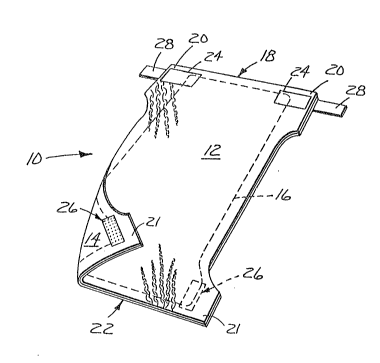
incontinent adult. The disposable diaper 10 shown in
Fig. 1 would conventionally be at least a three-layer
composite including a liquid permeable, user contacting top
sheet 12, a liquid-impervious outer shell or back sheet 1
and an absorbent layer 16. At the back panel 18 of the
diaper are corners 20 that overlap with corresponding
corners 21 at the front panel 22 of the diaper when the
diaper is worn. On the top sheet 12 side of the diaper at
each of the corners 20 is loca-ted a release treated,
non-woven release tab 24 and on the outer shell or
backsheet 14 at the front corners 21 of the diaper 10 are
mechanical type fasteners 26 of the invention.
For most conventional designs, the fastening tabs
28 are located at the back panel 18 attached at least to
the back sheet 14 of the diaper 10. During non-use, the
tabs 28 would be located on the non-woven release treated
tabs 24. When in use, the fasterling tabs 28 would be
removed from the release treated non-woven tabs 24 and
attached to the front panel 22 of the diaper back sheet 14.
Generally, the diaper front panel 22 is provided with a
landing or frontal strip 25, as shown in Pig. 2, which
reinforces the diaper at the waist portion of the diaper
front panel 22, allowing removal and replacement of the
fastening tab as necessary. The side edge portions of the
-4-
J . . j
diaper are also provided with elasticizing elements 17,
also shown in Fig. 2, which provide for engaging the leg or
thigh of the wearer when the diaper is in use. The diaper
can be constructed by any conventional means, as is
disclosed in Toussant et al.
Conventionally, the top sheet 12 of the diaper is
a soft, non-irritating fabric to prevent irritation of the
wearer's skin. Further, the top sheet 12 is made liquid
permeable to permit passage of liquids to the absorbent
layer 16. Top sheet fabric is generally fibrous woven or
non-woven sheets formed of, e.g., natural fibers, such as
cellul~se, or synthetic fibers of polyester, polyethylene,
or polypropylene sr a combination thereofO Further, the
: fibers may or may not be treated or contain additives
depending upon the surface characteristics of the fiber and
lS the desired properties of the top sheet. Other materials
capable of passing moisture to the absorbent inner layer
are also possible, such as a formed film or foam, e.g., a
reticulated foam, as is known in the art.
The topsheet 12 can be formed by any suitable
method including woven manufacturing such as weaving~ and
non-woven manufacturing such as spinbonding, bondingr
carding, etc.
Fastening tab 28 will generally be permanently
fixed to back sheet 19 at corners 20, although other
placements are possible, by any suitable method.
Generally, pressure-sensitive adhesives are preferred to
fix the tab 28 to the back sheet 14. However, in addition
to using pressure-sensitive adhesives, the fastening tabs
28 can be directly heat sealed to the back sheet 14 or
adhered using a heat or solvent activated adhesive,
depending upon the nature of the back sheet. The
mechanical fastener 26 and release tabs 24 (if separately
attached) can similarly be attached by any conventional
method as described above with respect to the fastening
tabs. The opposite end of the fastening tab 28 will be
releasably attached to the tabs 24 when not in use and
--5--
~ 3(~ 3
removed by the user for placement on, e.g., the frontal
strip 25 on the back sheet 14 front panel portion. This
will cause overlap of corners 20 and 21. Generally, the
user or free end of the fastening tab 28 is provided with a
pressure-sensitive adhesive which will releasa'oly adhere to
the front panel portion.
In accordance with the above described preferred
embodiment, the inner fastening means is provided on the
back sheet 14 of the diaper at corners 21, which inner
fastening means comprises the mechanical fastening means
26. This mechanical fastening means 26 is provided to
primarily resist sheer forces which may cause the
overlapping corners 20 and 21 to shift relative to each
other when the diaper or incontinence article is worn.
Release tab 24 shown is located on the top sheet
side of corner 20. The top sheet face of corner 20 will
overlap with the back sheet face of corner 21 when the
diaper is assembled as shown in Fig. 2.
The mechanical fastening tab of the invention is
designed to permit ready penetration into non-woven and
other foraminous substrates, as would likely be used as a
diaper topsheet, or in like articles or garments. The
mechanical fastener depicted in Fig. 3 comprises a backing
3~, which is preferably flexible. From at least one face
of the backing projects an array of upstanding stems or
projections 34 having, generally, blunt or pointed tips.
The projections as shown are in rows, however, any suitable
arrangement can be employed which will permit ready
penetration into the foraminous substrate being used.
The stems 34 and the backing 30 are preferably
flexible with the stems somewhat resistant to compression
or bending when in use. Materials suitable for forming
this integral structure include substantially any
thermoplastic material useful in the production of films.
Preferred of such thermoplastic materials are tough
thermoplastic resins of polyethylene, polypropylene,
polyesters, polyamides (e.g., nylon), and copolymers
--6--
3 ~
thereof. These materials can be used to form the
mechanical fastener by any suitable methGd including cast
or extrusion molding.
The backing can be quite thin depending on the
application. Generally, a thickness of about 25~m is
5 needed to prevent breakage during use. Thicker backings
can be used depending on the particular end use and the
strength required therefore. Generally, thinner backings
are preferred for disposable diapers and the like in terms
of material flexibility, conformability and cost.
The stems can be of any shape which permits ready
penetration into a foraminous substrate. This shape is
preferably one which has an inward taper away from the
backing face, such as a pyramidal or conical shape.
However, a shape with a slight inward or outward taper is
contemplated if the shape does not significantly interfere
with substrate penetration. Outward tapers or traditional
mechanical fastener structures at the top of the stems are
not preferred as they complicate fabrication and are not
required for the invention high shear strength fastener.
The tip 35 mean diameter is generally from 0.5 to
15 mils (12.7 to 381 ~m) for use on a standard diaper
non-woven material, with 2 to 8 mils (51 to 203 ~m) being
preferred. The mean diameter of the stems at their base 36
is generally 1.5 to 20 mils (38 to 508 ~m), with 4.5 to 12
mils (114 to 305 ~m) being preferred. with preferred mean
stem diameters, a minimum of approximately 25 stems per
square inch (3.9 stems/cm2) is preferred, with up to 2,500
stems per square inch (388 stems/cm2) having been
demonstrated as feasible, with a minimum of approximately
50 stems per square inch (7.75 stems/cm~ being most
preferred. However, use of over at least 1,000 stems/in2
(155 stems/cm2) is generally not preferred as there is no
significant increase, and generally a slight decrease, in
performance over this stem density. Further,
3~ theoretically, performarce will decrease significantly at
extremely high stem densities due to adjacent stem
--7--
~ ;3~
interference with fiber penetration. The lower stem
densities, although functional, are not generally as
desirable due to their coarse feel. The higher the stem
density, the less noticeable is the fastener when in
contact with the human body. An overall preferred range of
stem densities would be from 75 to 1,000 stems/in2 (10.65
to 155 stems/cm2).
Stem height is also important, with a height of 5
to 20 mils ~127 to 508 ~m) beimg preferred, and with 10 to
15 mils (254 to 381 ~m) being more preferred. Stem heights
lower than the preferred minimum do not easily penetrate
foraminous substrates, specifically non-woven materials. A
stem height above the preferred maximum will have a
tendency to bend when subjected to shear forces,
particularly when the stems do not fully penetrate the
foraminous substrate. Further, higher stems do not offer
any significant performance increase for the added costs
associated with their manufacture. A fastener formed of
the stem-faced material preferably will be of size such
that it will provide a shear force resistance of at least
500 grams, and preferably at least about 750 grams, when
placed against a substrate at a pressure of approximately
17 grams/cm2. The fastener size is limited only by the
substrate available for attachment. The fastener, however,
is preferably small in terms of cost, conformability to the
: 25 wearer, wearer comfort and ease of use.
The back face of the mechanical fastener is
preferably substantially flat to permit application of an
adhesive layer 38 for substrate attachment purposes. ~n
advantage with the invention material when using an
adhesive layer 38 is that the stems permit the adhesive
backed fastening material to be formed into a roll prior to
fabrication. The stems present a relatively low surface
area available for adhesive contact such that the material
can be wound as a roll then unwound without the necessity
of treating the stem face with a low adhesion backsize.
This allows for convenient manufacture, storage and
--8--
~@ .~ ,3
shipment of the bulk material prior to formation and
assembly of the mechanical fastener on the garment (e.g.,
such as a diaper as described above).
The mechanical fastener can be used in other
garments for purposes similar to that in the diaper
configuration described above. Generally, where a garment
or the like re~uires a fastener with high shear resistance
and little or no peel resistance, this mechanical fastener
could find use. Further, the Eastener could be used in
close conjunction with a conventional adhesive or
mechanical fastener to provide shear enhancement. The
fastener, in this case, could be integral with or closely
adjacent the conventional fastener such as on a separate
area of the same backing.
The following non-limiting examples serve to
illustrate the invention, however, are not intended to be
limiting thereof.
Example 1
One piece (2 in. by 3 in. (5.1 x 7.6 cm)) of film
(4.5 mil (114 ~m)) thick prepared by cast extrusion of a
polypropylene homopolymer resin (Fina Dypro 8771, 9 melt
flow index) was placed on a metal plate which had the
negative impression to produce a stem geometry and pattern
as illustrated in Fig. 3 of the drawings. A flat metal
plate was placed on top of the film. This was pressed in a
platen press at 2500 psi (176 kg/cm) and 330F (151C) for
5 seconds. The press was then opened for 5 seconds, then
closed again for 15 seconds. Then, after air cooling for
20-30 minutes, the embossed film was removed. Physical
dimensions of the stems are reported in Table I.
~,~3'~ ,?'~
Table 1
Stem Center-to
Stem Width Stem Center
Height at saSeDensityStem Spacing
Sample (~m) (~m)(per/cm )(~m) ~2
1. 152 189 25.1 2,145
2. 203 202 12.9 39002
3. 203 202 37.0 1,766
4O (1) 203 150 3~7.5 500
5. 254 ~14 62.0 1,250
6. 254 214 172.2 750
; 7. ~3) 330 233 4.1 14
8. 330 233 8.2 3,753
9. 330 233 25.1 2,1~5
10. 330 233 41.5 1,668
ll. 457 26~ 12.9 3,002
12. ~57 264 37.0 1,766
13. 508 276 25.1 2,145
(1) Sample 4 was drilled with a 4 mil (101 ~m) stem tip
while all others incorporated a 6 mil (152 ~m) tip.
(2) Samples 1-3 and 8 13 were drilled with staggered holes
with uniform spacing between holes. Samples 4-6 were
drilled in perpendicular rows with uniform spacing
between rows.
(3) Sample 7 was created by removing every second stem on
sample 8.
(4) This sample did not have uniform stem spacing due to
the fact that it was produced by removing every second
stem fro~ a staggered pattern.
.
ple 2
Molten resin (Dypro M 9618, an ethylene propylene
copolymer from Fina Oil and Chemical Co., Dallas, Texas),
was continuously cast onto a rotating steel forming roll
using a standard single screw extruder. The forming roll
had an array of holes drilled in it representing the
negative of a desired projection geometry and spacing. The
holes were formed in the forming roll with Minitool
microdrilling heads, available from Minitool, Inc.,
Campbell, CA. To facilitate flow of the molten polymer
into the holes, the surface of the forming roll was exposed
to a vacuum (46.8 mm of mercury) during the casting process
using a vacuum chamber preceding and attached to the
extrusion die and seated directly on the forming roll. The
temperature of the forming roll was maintained at about
35C by standard means of internal roll cooling with
circulating water.
A gap was provided between the extrusion die and
the forming roll to allow sufficient molten resin to be
applied to the forming roll to fill the holes and provide a
backing integral with the resulting projections when the
quenched resin was stripped off of the forming roll to
yield the backing of Example 2. The stems were pyramidal
with approximately 26 stems/cm2, a stem height of 760
microns, a stem width at the base of 410 microns and a stem
spacing center-to-center of 1,270 miorons.
Example 3
Various of the materials were tested for shear
resistance in accordance with the method outlined in U.S.
Patent No. 4,699,622. The samples, 2.5 in. x 2.5 in.,
were placed on a friction sled. A piece of foam and the
non-woven, with the foam underneath, were taped to the
friction platform of the peel tester (Instrumentors, Inc.
Model 3M-90). The non-woven was a spunbond polypropylene
with a basis wieght of 60 gm/m2 purchased from James River
~ 3 " ~
Corporation. The sled was then run over the platform and
a shear value was obtained. A baseline value was obtained
by placing standard diaper polyethylene on the sled. The
wrapped sled was used alone, which had a weight of
approximately 200 gm (5 gm/cm2), and with additional
weightsr for a total of approximately 700 gm ~17 gm/cm2).
For the 700 gram weighted sled, this baseline shear value
was 400 grams, and for the 200 gram sled, the baseline
shear was 128 grams. The measured results were translated
to what would be obtained with a 1 in. x 2.5 in. sample by
the following equation:
2.5 in2 6.25 in2 sample size base
[test result ~ . line ]
sample size 6.25 in2 value
The shear resistance obtained for the tests run
with the sled and the weighted sled are set forth in
Table 2.
Table 2
Sled ShearWeighted Sled
Sample ~m) _ _Shear (gm)
1. 389 691
2. 471 828
3. 461 856
4. 698 1,133
5. 578 1,011
6. 701 1,2~0
7. 263 683
~. 463 868
9. 514 888
10. 463 1,093
11. 419 695
12. 556 745
13. 449 896
-12-
~ r C~ fi)
other embodiments of the invention will be
apparent to those skilled in the art from consideration of
the specification or practice of the invention disclosed
herein. It is intended that the specifications and
examples be considered as exemplary, with the true scope
and spirit of the invention being indicated by the
following claims.
39
-13-