Note: Descriptions are shown in the official language in which they were submitted.
2026 1 42
This invention relates to driver training and testing
apparatus for land vehicles, and, more particularly, to improved
apparatus for training and testing operators of complex, or heavy,
or large vehicles, such as tractor-trailers, buses, and various
military vehicles. One object of the present invention is to
provide a simulator system which is readily adaptable to simulate
operation of a variety of complex, or heavy, or large land
vehicles. The invention will be illustrated in connection with
simulation of a tractor-trailer but it will become evident that
major principles of the invention apply to a variety of other land
vehicles.
Thorough training of a tractor-trailer driver involves
numerous situations which markedly differ from those encountered in
automobile driving. Both starting and stopping may involve factors
lS not encountered in a car. Backing a trailer up to a loading dock
looks simple as an expert does it, but it requires much practice by
most individuals. Maneuvers such as parallel parking, jackknife
parking, and other maneuvers commonly performed by experienced
drivers require large amounts of practice or training time before
many individuals can perform such tasks proficiently.
The fifth-wheel, or articulated, connection between a tractor
and a`trailer considerably complicates the operation of a tractor-
trailer combination, requiring much more training or practice in
the operation of such a vehicle than what is required for a more
common vehicle, such as an ordinary automobile. It is possible to
provide some valuable training in tractor-trailer operation by
projection of previously-photographed, or "canned", scenes. One
such training system is shown in U. S. Pat. No. 4,846,686.~ecently
issued to the assignee of the present invention. I~ long has been
well known, however, that training is much more effective if it is
~-- "interactive", i.e., if trainee operation of controls appropriately
varies visual cues presented to the trainee. Highly interactive
training equipment has been provided to train pilots and astro-
nauts, but at enormous expense. One object of the present
2 ~
2026 ~ 42
invention is to provide economical interactive method and apparatus
for training operators of tractor-trailers and other heavy land
vehicles.
DESCRIPTION OF THE PRIOR ART
The broad idea of projecting to a trainee at a dummy control
station, the video scene viewed by a video camera whose position
and attitude were controlled by the trainee, has been old, since
the l950s, or perhaps even earlier. In a 1950's aircraft simulat-
or, a video camera controlled in position and attitude relative to
an airport model by trainee (pilot or co-pilot) operation of dummy
aircraft controls, transmitted a video picture which was projected
for viewing by the trainee pilots. The very large expense of
providing training in an actual aircraft justified the high cost of
the video system provided for the simulator. To provide useful
aircraft landing training, the aircraft simulator required that
altitudes be depicted over a very wide range, from several thousand
feet down to where the pilot view was only 10 feet above the
runway. Provision of an optical system which would accommodate
such variation with a practical size of airport model presents a
formidable problem. In such systems the scaling or magnification
which was used usually required that a lens representing the
pilot's view be driven down to an extremely small fraction of an
inch above the terrain model, as the simulated aircraft made a
landing. Lens damage from collision with the model was often
encountered. The use of the large scale-reduction needed also
tended to cause unrealistic "jumps" in a visual display if backlash
or limited system dynamics were present. The problems as60ciated
with such "TV camera-model" visual display systems long ago
resulted in departures directed toward other types of visual
display systems, such as variable anamorphic motion picture
systems, and more recently, computer-generated image displays.
Computer-generated image displays are typified by extremely large
20261 42
cost, and very little realistic detail. "Camera-model" systems
have had little use for many years.
In accordance with one concept of the present invention, it
has been recognized that the most important tasks for which
training is required in connection with many land vehicles, do not
require large scale-factor magnification changes like those
required for aircraft simulation. While the altitude of the
pilot's eye may vary from say 6000 feet to 10 feet (i.e., by a
ratio of 600) in an aircraft simulation, the present invention
,~,.. , . _ ... ..... . .
recognizes that no such variation is required in a land vehicle
trainer, wherein altitude change is either zero or negligible. It
also has been recognized that a very large percentage of the
procedures which must be repeatedly practiced to master operation
of a tractor-trailer, or like vehicle, are, much unlike aircraft
procedures, short distance procedures. While a tractor-trailer
trainee could benefit to some degree by realistic simulation of a
one-mile or two-mile trip down a highway, the tasks which require
the most practice are those encountered when the operator must
maneuver his tractor-trailer within a relatively small space, such
as within a small truck terminal or factory yard. Highway travel
~-- in a tractor-trailer mainly involves steering and paying attention
to the position of one's vehicle relative to lanes and to the
presences of other vehicles. Highway travel in an ordinary
automobile involves the same considerations. Because most, if not
all, persons being trained to drive tractor-trailers are already
trained to operate automobiles, less training in highway travel is
required compared to that required in what may be termed "short-
distance" maneuvers. The short distance maneuvers mainly involve
(a) starting and stopping (b) straight-line backing (c) backing
straight toward a dock (d) offset right and offset left backing (e)
left and right parallel parking (f) left and right turning during
forward travel, (g) left and right turning during backward or
reverse travel, (h) backing toward a dock in a narrow passageway,
and (i) backing toward a dock not visible to the operator.
20261 42
In accordance with another important concept of the present
invention, the visual display presented to the trainee incorporates
inter2ct1ve detail, which includes views of rearward portions of
the simulated vehicle. Aircraft operation seldom, if ever,
involves rearward views by a pilot, but conversely, in training
operators of tractor-trailers, rearward views often tend to be more
important than forward views.
In the present invention, since vehicle altitude need not
change appreciably, some important visual information of a type
never obtained in prior aircraft simulators can be readily obtained
and projected for view by a trainee, at quite reasonable cost.
In accordance with one concept of the present invention, a
camera view of portions of a miniature vehicle controlled by a
trainee is projected for viewing by the trainee. For example, as
a trainee maneuvers a simulated tractor-trailer from his trainee
station, he may view the changing scene or scenes which a driver
would view generally forwardly through the windshield of a tractor
cab, and also view what a driver would view in and around one or
two rear-vision mirrors, as similar movements are made with an
actual tractor-trailer.
The invention accordingly comprises the features of con-
struction, combinations of elements, and arrangement of parts,
which will be exemplified in the constructions hereinafter set
forth, and the scope of the invention will be indicated in the
claims.
For a fuller understanding of the nature and objects of the
- invention reference should be had to the following detailed
description taken in connection with the accompanying drawings, in
which: ,
Fig. 1 is a frontal perspective view showing the trainee's
station, a screen, and television projector means in one embodiment
of the invention.
Fig. 2 is a rear perspective view of the apparatus of Fig. 1.
Fig. 3a is a plan view of the trainee's station.
:.
2g26 1 42
Fig. 3b is a plan view of one form of diorama, or terrain
-- model.
Fig. 4 is a perspective view of one form of miniature tractor-
trail~-: used in one successful embodiment of the invention.
Fig. 5 is a perspective view of the miniature tractor-trailer
of Fig. 4 with various parts removed or cut away, to show a
plurality of camera heads or lens barrels situated at the driver's
point of view in the miniature tractor, and the electronics
associated with such lens barrels carried in the miniature tractor
- 10 portion of Fig. 5.
Figs. 6, 7 and 8 are respectively plan, front elevation, and
side elevation diagrams illustrating a preferred video camera
arrangement for the embodiment depicted in Figs. 1-12.
Fig. 9 is a perspective view showing one form of diorama or
terrain model according to the invention, with a miniature tractor-
trailer ensconced thereon, and
Fig. 10 is a plan view of the apparatus of Fig. 9.
Figs. 11, lla, and llb depict front windshield, left window,
and right window views, respectively, seen by the trainee while the
tractor-trailer is at a turned condition, such as that seen in Fig.
10 .
Figs. 12, 12a and 12b depict front windshield, left window,
and right window views, respectively, while the tractor-trailer is
in a "straight-ahead" condition, such as that shown in Fig. 3b.
Figs. 13 and 14 are perspective views illustrating two ways in
which cabling associated with the invention may be trained in some
embodiments of the invention.
Fig. 15 is a combined electrical schematic-block diagram
"~ illustrating the electrical arrangement between a driver trainer
portion and a miniature truck portion of the invention.
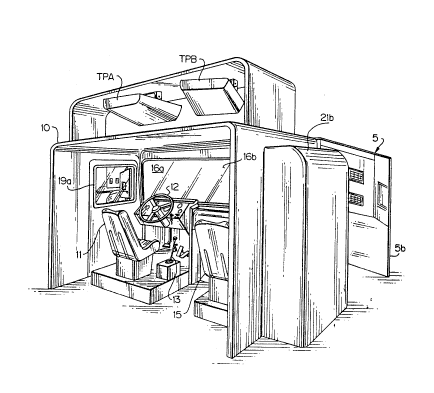
Referring first to Figs. 1 and 2, the assembly thereshown
includes a cab shell 10, the interior of which is fitted to
resemble the interior of a typical tractor cab. Within the cab
shell are a driver or trainee's station which includes a seat 11,
2026 1 42
and various dummy controls such as a simulated or dummy steering
wheel 12, a dummy gear shift lever 13, and various other dummy
controls which are common in driver trainers, such as an ac-
celerator pedal, a brake pedal, and a clutch pedal. Gear-shift
operation is an important aspect of driving many trucks. A dummy
10-speed manual transmission control, for example, may be included
in some embodiments of the invention, or perhaps a 5-speed
automatic transmission control, as another example. Further, the
cab shell 10 of the invention may desirably include both manual and
automatic transmissioh dummy controls, so that a trainee can gain
proficiency with both systems. In addition to the mentioned
controls, the trainee station ordinarily will include a variety of
dummy switches which correspond to switches of the following types
in an actual truck: headlight switch, trailer running-lights
switch, engine stop switch, trailer air supply switch, system
parking brake, turn signal and flasher switch and ignition switch.
The cab also includes a plurality of dummy indicators, such as a
speedometer, tachometer, fuel gauge, ammeter, oil pressure gauge,
temperature gauge, air pressure gauge, oil pressure light, and
various other indicators. In Fig. 2 a second seat 15 is shown
provided for occasional use by an instructor. In one embodiment of
the invention the trainee station largely resembled an L-225 driver
trainer system which has been widely sold by the assignee of the
present invention. The dummy controls and dummy indicators are
connected to a micro-controller of the driver trainer system.
Signals from the driver trainer system operate the dummy indicators
within cab shell 10, and signals from the system are routed to
control a miniature vehicle V (Figs. 4,5). Fig. 15 illusitrates a
known form of driver trainer. Output signals from the micro-
controller of the driver trainer are applied via known interfacecircuitry shown as a simple block to various circuits within the
miniature truck V. The interface circuits provided buffering and
voltage level-shifting in accordance with techniques well known in
the art. In the mentioned embodiment, the steering servo, the
2026 ~ 42
traction or drive motor and the gear select servo motor shown all
were standard parts of the mentioned Wedico toy, which is ordinari-
ly radio-controlled. For purposes of the present invention an
electromechanical clutch-brake assembly was added to provide clutch
and brake functions aboard the miniature vehicle. The clutch-brake
assembly comprised a Model UCB-12CC-4-4-12V assembly from Electroid
Company of Springfield, New Jersey. Numerous other techniques for
sensing operation of driver trainer operator controls and providing
suitable output signals for dummy indicators and the like are well
known in the driver~trainer art and are available for use in
connection with the present invention. While signals from the
driver trainer system are shown below to be applied to a miniature
vehicle V via wires of an overhead cable, it will become evident to
those skilled in the art that one or more of those signals can be
communicated to the miniature vehicle via one or more radio links,
using a given frequency for a given control, for example, or by
multiplexing, so that a given frequency handles data for plural
-~~ controls.
Using a single radio frequency, serial bits of one or several
digital words can be readily sent to the miniature vehicle,
detected there and used to control the vehicle. Techniques
required for such serial transmission are widely used to send data
to serial printers used with the personal computers. Bytes or
words transmitted to the miniature vehicle may control groups of
boolean (on-off) functions, or single functions, such as a motor
speed, as will be readily evident to those skilled in the art.
The front of cab shell 10 i5 shown containing an open window
space 16 simulating a windshield. During operation of the
invention, a trainee seated in seat 11 operates the ~entioned dummy
controls, at times viewing a forward scene through simulated
windshield opening 16, and at times viewing sidewardly and/or
rearwardly. The forward scene viewed by the trainee is projected
onto screen S by television projectors shown at TPA and TPB. In
addition to the simulated central or forward view visible on screen
2026 1 42
S through windshield opening 16, the trainee may view a left-side
display located at window l9a (Fig. 2), and a generally similar
right side display l9b not visible in Figs. 1 and 2. The displays
l9a,19b are produced by video monitors (20a, 20b, Fig. 3a) located
within housings 21a,21b in Figs. 1-2, housing 21a not being visible
in Figs. 1 and 2. The displays l9a,19b correspond generally to
what a driver might see through left-side and right-side windows of
the cab of a tractor, and importantly, those displays include
varying rearview mirror or rearview reflector displays. In the
plan view of Fig. 3a screen S is shown as an angled screen having
two sections Sa,Sb onto which the two video projectors TPA, TPB
respectively perpendicularly project. The trainee's point-of-view
is shown at DPOV. In the mentioned embodiment each screen section
was approximately 80 in. (203 cm.) wide and situated approximately
106 in. (269 cm.) from the simulated windshield of shell 10 and
about 132.6 in. (337 cm.) from its associated projector; and
projectors TPA and TPB each comprised a SONY Model VPH-1041Q/1041QM
color video projector. The monitors 20a, 20b may comprise, for
example, 25-inch (63.5 cm.) Panasonic color television monitors
Model No. CTL-25805 widely sold throughout the United States.
While two projectors are shown used in Figs. 1-12 to produce the
forward views, it should be recognized that one projector, or
-- perhaps three (or more) projectors could instead be used, with an
-~ appropriate number of associated cameras being used, of course, in
each case.
The video signals required to produce the four displays for
windows 16a, 16b, l9a and l9b are provided by four video cameras
VC-1 to VC-4 (Figs. 5 and 6) carried within the cab portion of a
miniature vehicle V.
The exemplary miniature vehicle V depicted in Figs. 4 and 5
and used in the mentioned embodiment of the invention includes a
Model 362 3-axle chassis, a Model 205 "Freightliner" (trademark)
cab, and Model 010 trailer, all available from Wedico Technik GmbH,
Wuppertal, West Germany. Those mentioned model components are
,,"", _ . . .~,
i 2026 1 42
constructed on a scale of 1:16 compared to their real-life full-
size counterparts, and the same scale factor is used in construc-
tion of the diorama or terrain model to be described. A wide
variety of electrically-controlled and electrically-driven model
vehicles of different types are available from Wedico, with many of
them intended to be used as radio-controlled toys. It will be
apparent that many other types of electrically-driven model
vehicles may be made in order to provide realistic training in the
operation of many other vehicles.
The mentioned scale factor of 1:16 is by no means crucial in
the present invention. It should be noted, however, that use of a
scale change which is much, much less than that used in aircraft
camera-model systems allows one to provide much more realistic
displays at much less expense.
The lens barrels or camera heads and charge-coupled sensor
portions of four video cameras VC-1 to VC-4 are located with the
cab portion of miniature vehicle V, each camera pointing in a
different direction. The field-of-view of camera VC-1 includes a
front-surfaced miniature rearview mirror or reflector 22a added to
and carried on the tractor of vehicle V, and the field-of-view of
camera VC-4 includes a similar rearview mirror or reflector 22b not
visible in Fig. 4. One suitable form of camera is the Model GP-CD1-
industrial color CCD camera available from Panasonic Industrial
Company, Secaucus, New Jersey. Such video cameras comprise a
camera head only 0.67 in. (17 mm.) in diameter and only 1.87 in.
(48 mm.) in length, with cabling to a nearby (less than 2 meters)
camera control unit, having dimensions of 5,38 in. (138 mm.) by
1.65 in. (44 mm.) by 6.63 in. (169 mm.). In the miniature;vehicle
of Figs. 4 and 5, the four small camera heads VC-l to VC-4 are
situated within the miniature cab portion, but the four camera
control units are carried within the miniature trailer portion of
vehicle V at 24,24 with the camera heads being connected to
respective camera control units via wiring shown at W in Fig. 5.
The small size of the camera heads contributes significantly to use
2026 1 42
of a small miniature vehicle and small terrain model, and hence to
economy. The trailer portion of vehicle V also includes a battery
25 used to power the video cameras as well as the motors and other
electrical equipment aboard miniature vehicle V. In the mentioned
embodiment battery 25 comprised a conventional lead-acid motorcycle
battery.
In Figs. 4 and 5 cabling CB is shown extending vertically from
the trailer portion of vehicle V. The cabling routes signals from
the driver trainer system to control motors, switches, and lights
aboard the miniature-vehicle, and routes video signals from the
four video cameras back to the video projectors and monitors.
Means training cabling CB must keep the cabling trained generally
upwardly, so that the cabling does not appear within the fields-of-
view of cameras VC-l and VC-4, but vehicle V must be allowed to
move within the confines of the terrain model. A variety of
techniques for appropriately training the cable are readily
available. A pair of X,Y carriages can be moved in cartesian
coordinates to maintain a length of cabling substantially directly
above the trailer portion of vehicle V, or a rotating arm having a
radially moving carriage can instead provide the same function in
polar coordinate fashion, such arrangements being discussed below
in connection with Figs. 13 and 14.
The plan view of Fig 3b depicts one exemplary form of diorama
or terrain model. The same exemplary form of terrain model is
depicted isometrically in Fig. 9, with the miniature tractor-
trailer V situated in a different position.
The exemplary model of Fig. 3b measured 228 by 180 inches
(5.79 by 4.57 meters) and was constructed atop plywood;boards.
With a 1:16 scale factor it simulated a space which,is 304 ft. by
204 ft. (92.66 by 73.15 meters). Strip areas labelled SW in Fig.
3b represent sidewalks, stippled areas labelled GR represent grass
area, areas labelled STR represent street area, and areas labelled
BLDG represent buildings, and lengths of walls labelled BW
represent building walls. The heights of the simulated building
2026 1 42
walls need not exceed, of course, the portions which may be seen by
a trainee in any of the views depicted by projectors TPA, TPB and
monitors 2Oa,2Ob.
".,,",,., . , , , . ., ~ .
A plurality of model cars CA,CA are shown located atop the
model, as is the miniature vehicle V controlled by the trainee, and
a second scale-model vehicle V2 not controlled by the trainee. The
model cars CA and model trucks such as V2 may be readily varied in
number and/or manually moved around atop the model to increase the
difficulty of various driving tasks as a trainee gains proficiency.
Model truck V2 may be arranged to be controlled remotely by an
instructor, ordinarily to provide very simple motion of model
vehicle V2. If vehicle V2 is caused to move in a direction which
might cause a collision with vehicle V, the trainee controlling
vehicle V can be given valuable practice in how to avert col-
--- 15 lisions.
A scale-model wall WA extending parallel to one of the
simulated buildings provides what is often called an "alley dock"
at AD, creating a situation in which an operator must back his
tractor-trailer through a very narrow space to spot the rear end of
the trailer adjacent dock AD, without scraping the trailer against
wall WA or the building, and without ramming the trailer into dock
; AD at undue speed. A second wall AW is shown angled to provide two
angled loading docks Al,A2, and a plurality of parallel loading
docks are simulated at D1 to D5. While the diorama is shown for
sake of simplicity as having only level spaces through which
vehicle V may move, it should become evident that some inclined
simulated alleyways and driveways may be readily included to allow
trainees to gain proficiency in such common tasks as having to back
down an incline toward a dock, or to provide training in starting
and stopping on an incline.
The diorama or terrain model ordinarily will be flooded with
a large amount of overhead light to facilitate simulation of
daytime driving conditions, but the amount of overhead lighting
preferably will be controllable by an instructor, so that trainees
12
2026 1 42
may view dusk or night-time maneuvering problems as well as daytime
problems.
Further, the loading dock structure and like model structure
associated with the terrain model may include various features
controllable by the instructor which provide significant training.
For example, dummy lights on the diorama terrain model normally
intended to aid the trainee as he attempts to back up to a loading
dock may be obscured by additional lighting which greatly increases
the difficulty of the trainee driver's task.
The manner in which the four video cameras are aimed relative
to the trainee eye position and the miniature rearview mirrors in
the miniature vehicle in the mentioned exemplary embodiment is
shown in the plan, front elevation and side elevation views of
Figs. 6, 7 and 8. The angles and other dimensions depicted in
those drawing figures will vary, of course, in various embodiments
of the invention. In the mentioned successful embodiment,
dimensions were as follows:
Miniature cab width _ 6.125 in. 15.56 cm.
Control camera angles al 24 degrees
- 20 Outside camera angles a2 21 degrees
--~ Monitor angle a6 22 degrees
Distance d2 10 inches
Projection system angle a7 78 degrees
Mirror angles a3 30 degrees
Mirror widths _ 0.90 in. (2.25 cm.)
Mirror longitudinal
position x1 1.20 in. (3.05 cm.)
Displacement x2 0 to 1.00 in. (2.54 cm.)
Mirror lateral position y~ 0.65 in. (1.65 cm.)
Radius r1 0.90 in. (2.54 cm.)
Radius r2 1.10 in. (5.21 cm.)
Mirror vertical position zl 0.50 in. (1.21 cm.)
Camera vertical position Z2 1.20 in. (3.56 cm.)
- Angle a4 10 degrees
Angle a5 10 degrees
13
- ; ~
~f l ~
20261 42
Mirror length z3 1.5 in.
In one simplest mode of the invention, the model is brightly
lighted from above, generally uniformly, to provide a display
resembling that seen on a bright overcast day. Lighting may be
diminished to simulate d;min;Fihed visibility conditions.
Some important features of the present invention may be better
appreciated by considering, together, Figs. 9, 10, 11, lla, llb,
12, 12a and 12b, all of which figures are co-ordinated, as is Fig.
3b.
In Figs. 9 and 10 the cab of vehicle V is shown so that a
straight-ahead forward view (lines 51 in Fig. 10) from the cab is
directed slightly to the left of angled loading docks Al,A2. A
leftside view along line 52 will encompass not only stationary
diorama objects, such as the model car CA3 shown in Figs. 9, 10 and
lla, but also matter displayed in the leftside rearview mirror, as
indicated at 53 in Fig. lla. The view seen at 53 is taken, of
course, along line 55 in Fig. 10. It includes a building corner CO
(Figs. 10 and lla), and a front leftside corner portion of the
trailer of vehicle V at 61. A rightside view along line 54 in Fig.
10 will encompass not only some parallel loading docks (of the
" ~ group D1 to D5), but also part of parked vehicle V2, as shown in
Fig. llb. It is important to note that the leftside and rightside
views in Figs. lla and llb show much different amounts of the
trailer portion of vehicle V, the clockwise (in Fig. 10) orienta-
tion of the cab relative to the centerline of the trailer resulting
in much more trailer being visible in Fig. llb than what is visible
in Fig. lla.
In Fig. 3b the cab of vehicle V is shown alig,ned "straight-
ahead" with the trailer. The left and right monitor (or side-
window) views presented to the trainee depict much different views,as can be seen by comparing the leftside view of Fig. 12a with the
rightside view of Fig. 12b; however, and what is crucial to a
trained tractor-trailer operator, the amount of trailer visible in
~: ~
14
2026 1 42
the rearview mirror of Fig. 12a equals the amount of trailer
visible in the rearview mirror of Figs. 12b, irrespective of what
surrounds those rearview displays. The operator often must gauge
his steering solely on the differences or similarities between
those two rearview displays. However, at the same time, he must
also carefully note the visual data outside of and surrounding the
rearview displays. Keeping the cab aligned with the trailer does
little good if either of them runs into a forbidden area. Most
tractor-trailer maneuvering involves a combined association of
forward or sidewise views with the two rearward mirror views, and
provision of interactive simulation of that combination is believed
to be ~n outstanding novel and important feature of the present
invention.
Some very important visual cues which are practically
impossible to provide (or extremely expensive to provide) in prior
visual display systems are readily provided by the apparatus of the
present invention. As one example, as a tractor-trailer driver
backs up toward a building or other structure, the movement of a
shadow which his trailer casts on a building wall may indicate the
progress of the trailer toward the building, perhaps aiding the
driver. On the other hand, a shadow may tend to obscure a trailer
edge which the driver should be carefully monitoring, making the
maneuver more difficult. One further feature of the invention is
that shadowing effects which occur in the real world may be
simulated very realistically and economically.
The controls at the trainee station may include one or several
light switches, so that the trainee may turn on headlights on
vehicle V, and turn on trailer lights on vehicle V. Obser~ing, via
rearview mirrors, the patterns cast by trailer ligh,ts on walls or
loading docks as one backs a tractor-trailer may be the only
practical way of backing a tractor-trailer at night. Brake lights
ordinarily will illuminate when the driver presses the brake pedal.
The reflection of such lights from a loading dock as viewed through
20261 42
~, _ . ~ ... .
a rearview mirror, can be an important visual cue as a driver backs
the vehicle toward the simulated loading dock.
The cabling CB is shown extending upwardly from the miniature
trailer VT, so that it can never be viewed by any video camera via
S a rearview mirror, and it extends with some slack, so that the
cable does not impede movement of miniature vehicle V. The cabling
ordinarily will include four or so coaxial cables connected with
respective ones of the video cameras, and a varying number of
control wires. The control wires are connected to stop, start and
run the vehicle drive motor, to operate the clutch, steering wheel
-- and brake. In some embodiments of the invention, control wires may
be provided to illuminate miniature headlights and running lights
on vehicle V.
If the headroom available above the diorama terrain model is
sufficiently great in relation to the length and width of the
terrain model, cabling CB can extend down to vehicle V from a fixed
overhead location with a bit of slack and allow vehicle movement
over all of the terrain model. In some applications, as where
little headroom is available above the terrain model, cabling CB
may be routed to vehicle V using a technique such as that shown in
Fig. 13, or alternatively, that shown in Fig. 14. In Fig. 13 a
frame 28 supported above the terrain model includes slide bars
29,29 which slidingly support a carriage for movement in one
direction of a cartesian coordinate system. The carriage includes
slide bars which slidingly support a second carriage 31 for
movement in a second, perpendicular, direction. Training the cable
between carriage 31 and the projectors can be done in a variety of
ways which will be evident to those skilled in the art. I~ Fig. 14
a rotatable arm supporting cabling CB is rotated by pulling on the
cabling from vehicle V as the vehicle maneuvers to different
locations on the terrain model. It is contemplated that movement
of an overhead cable support ordinarily will be caused solely by
pulls which vehicle V applies to the cabling as it moves to
different locations on the diorama. If some embodiment of the
16
- .
2026 1 42
invention should incorporate a diorama of great dimensions,
movement of an overhead cable support can be readily provided by
driving the support to a computed position directly above the
trailer of vehicle V. The position of the trailer may be readily
tracked using very simple computer techniques which will be readily
evident to those skilled in the art.
In Fig. 14 two light sources are diagrammatically shown at LSl
and LS2. Source LSl projects light largely downwardly, largely
perpendicularly to the ground plane of the terrain model. While
source LSl is depicted as resembling an incandescent source, a
source which comprised a bank of fluorescent lamp strips extending
over the entire terrain model has been preferred in practice.
Lamp LS2 in ~ig. 14 is shown projecting light generally
downwardly toward the model, but at a considerable slant. With
such an arrangement miniature vehicle V will cast shadows on
various nearby objects, such as walls and loading docks. These
_- shadows which would be visible to a driver from an actual tractor
cab via a mirror will be visible to the trainee. In some cases
such shadows help the driver maneuver his vehicle, while in other
cases they obscure his view. In either case it is helpful for a
driver to gain experience under such conditions.
The light source or sources used to illuminate the terrain
model are preferably arranged to be readily varied in intensity,
which will allow truck travel to be simulated under varying degrees
of lighting ranging from a bright overcast condition to a very dim
dusk or night-time condition.
It will thus be seen that the objects set forth above, among
those made apparent from the preceding description, are efficiently
attained, and since certain changes may be made,in the above
constructions without departing from the scope of the invention, it
is intended that all matter contained in the above description or
shown in the accompanying drawing shall be interpreted as illustra-
tive and not in a limiting sense.
2026 1 42
. The embodiments of the invention in which an exclusive
; property or privilege is claimed are defined as follows:
18