Note: Descriptions are shown in the official language in which they were submitted.
2026542
A data carrier having an optically variable element
and methods for producing it
The present invention relates to a system comprising a series of data
carriers. in particular identity cards. papers of value or the like. ~.oherebv
the data carriers belonging to the system exhibit diffraction structures
containing standard information, to such data carriers and to methods for
producing them.
Optically variable elements have been known ir: v-arious embodiments
for some decades. These elernents have in common t:~at they shop- differ-
ent optical effects depending on the angles of vie;~ing and illumination.
One particular class of optically variable elements is based on diffractive
effects. It includes linear or structured diffraction grids, holographic
recordings, cinegrams and the like.
Optically variable elements are employed in a great variety of areas,
e.g. in advertising. decorating, but also for marking the authenticity of
data carriers. Due to their optical quality that has considerably increased
in the past while, holograms, cinegrams, diffraction grids. etc., are being
increasingly used in the security field, for example for credit cards, iden-
tity cards, bank notes. security documents, etc. The rise in popularity is
essentially due to two circumstances. Firstly, such elements meet the
traditional security requirements for humanly testable authenticity fea-
tures, i.e. high expenditure for production and imitation, poor availability
of the technology and unambiguous testability without additional aids.
Secondly, the elements are based on the newest state of the art so that
they give the corresponding product a modern, high-tech character.
In the patent literature and in their practical application in the secu-
rity field, such elements have become known up to now in various v er-
sions.
Very soon after the appearance of the first holograms the proposal
was made to protect identity cards. credit cards and the like from imita-
tion and falsification by storing the card user's personal data not only in ,
the customary photographic andior written form but also holographically
in a hologram on the card. ~ comparison between the conventional card
data and the data stored in the hologramw-~asw-intended--ta--prove--their---
2o2s~4z
correctness. Of the many relevant publications. German "offenlegungs-
schrifts" nos. ?5 O1 60=1. ?0 13 550 and ?5 -15 ~ 99 are stated by ~.vay of
example.
.-although the traditional security philosophL- requires the e:cpenditure
for producing authenticiy features to be high. this holds prirnarily for
the original value and the poor availability of the necessary production
equipment. The production of the authenticity features themselves. vc~hich
are to be produced in large amounts, should nevertheless be economical
on this relati~-els- expensive production equipment.
With various types of hologram. the preparation of the first hologram
is relatively troublesome and expensive. Ho~~,ever. it is possible to pro-
duce duplicates at a fraction of this "first cost."
Such embodiments thus prose to be disadvantageous not only because
the holograms must be produced on very expensive technical equipment
but also because separate holograms with individual information (person-
alization data) must be produced for each card. so that the technical
effort for preparing these individual holograms (unicates) is always rela-
tively high. -The cost -can be reduced only minimally by shifting the effort --
to the production apparatus. Due to these detrimental marginal conditions
the use of holograms with holographically stored card-specific data is
unreasonable Prom a financial point of view.
Different techniques are used depending on the type of data carrier
or of holographic standard element. Without laying any claim to complete-
ness one can state the following:
- directly embossing the hologram structure on the recording medium
which has a suitable surface quality, e.g. on plastics materials,
- heat-sealing or gluing a hologram provided on an intermediate car-
rier onto -the recording medium itself, which may have a paper or plastics
surface, e.g. bank note, paper of value, identity card, etc..
- laminating or mounting a hologram provided on an intermediate car-
rier into the interior of a multilayer recording medium,
- embedding safeguarding threads or planchets with holographic
diffraction structures in paper during the paper production process.
The process most frequently used today for producing and applying
standard holograms to data carriers is the transfer of embossed holograms
to identity cards. For this reason the production process and the indi-
... 3 202654
vidualizing measures shall be presenter) by ~oay of example ~.vith reference
to this technology. The essential method steps are the preparation of a
master hologram, the production of hologram copies and the application
to the subsequent product.
The master is generally prepared by manual single-piece production
mith very expensive equipment. The master hologram therefore involves
high cost. The copies can be produced and applied to the cover foils of
the cards automatically at high speed and thus at relatively lo~.c cost.
Due to this cost structure one endeavors to minimize the fired cost. per
hologram by preparing a maximum number of identical copies. The neces-
sity of mass production thus leads in the security field, in particular in
the card branch, to restrictions with respect to the holographic protec-
tion against forgery.
To reduce the cost of producing the hologram, embodiments have
become known in - which holograms are used as an authenticity feature but
the data stored in the hologram are not individualized for the user but
merely exhibit an individuality relating to the card issuer (standard holo-
grams). The holograms of different card systems differ from each other, -
but the holograms of the individual cards of a system are identical.
By using standard holograms (i,e. duplicates of a master hologram)
for a card system it now became possible to distribute the relatively high
fixed cost for the holographic recording technique over a high number of
cards. Depending on the extent of the card series, the cost may thus be
distributed over such high piece numbers that virtually only the duplica-
tion cost shows in the books for the price of the individual hologram.
This fact made holograms economically feasible as mass-produced articles
in the security field for the first time.
Along with the well-knocvn applications in the Eurocheck system and
for VISA and Mastercard credit cards, examples of these various applica-
tions are German "offenlegungsschrift" no. 33 08 831 and European patent
no. 0 064 067.
The holograms used in current credit card systems are known to be
so-called "embossed holograms," which allow for reproduction by means
of die-plates. Although a major part of the production cost arises for the
holographic recording technique, the cost to be calculated for reproducing
the holograms in series production is still so high that an economical
production is only possible if the necessary cost for the recording tech-
nique and the production of the hologram master can be apportioned
4
among series with many millions of pieces. The production of small lots.
i.e. a fesc ten thousands to one hundred thousand cards, is usually still
impossible for financial or economic reasons.
When using like holograms ~zithin a card series one can make cards
of one system differ better from cards of another: but the falsification of
cards is not fully excluded since such holograms can still be punched out
and transferred to other cards. 4leasures exist for making such manipu-
lation more difficult by shifting the embossed data relating to the card
user partly or completely to the hologram area. But it is well-known that
the embossed data can be reembossed, ~,c-hereby such manipulation is rec-
ognizable in practice only for experts, and not for laymen. The provision
of card-specific embossed data in the area of the standard hologram thus
fails to offer genuine protection from a transferral to other cards.
To avoid such problems Austrian patent no. 33:~ 117 describes the
application of standard holograms to the user-related individualization of
cards. According to this proposal the card individualization is permitted
by the combination) of sev era) standard holograms each containing certain
information of its own,. e.g. letters or numbers, and representing different
data, such as words, multidigit numbers, etc., through a corresponding
combination on the individual cards of a system. By embossing such holo-
grams with the aid of a standard set of press dies -one obtains a simple
and inexpensive production of individual holographic card data.
However, since alphanumeric data are mainly applied in this variant
and particularly pictorial data cannot be readily reproduced, the overall
impression of such holograms is visually not very effective, which is why
this form of individualization has not gained much acceptance on the
market up to now.
A further variant for individualizing documents using holograms is
described in German "offenlegungsschrift" no. 25 55 214. Here, it is pro-
posed that diffraction structures in the form of numerical or alphanumeric
characters be applied to a document. A thermoplastic ink is printed in
the form of numbers on a paper substrate, whereafter the diffraction
structure is embossed with a.large-surface die.
However, this variant is unsuitable for multilayer types of hologram,
which are particularly preferred for producing data carriers since the dif-
fraction structure is located inside and is thus protected.
The prior art shows that the existing needs in security technology
and the feasibility of economically reasonable solutions have not yet
CA 02026542 2000-10-26
7
found a common denominator.
~.ssuming this general view and the r elated prior art, the invention
is therefore based on the problem of proposing diffraction-structure ele-
ments. and in particular hologram ~-ariants and production methods for
them. that allow for a degree of individualization of the holograms ad-
apted to the particular securit~~ aspects. and thus for maximum protection
of the data and documents. awhile at the same time offering the cost
advantages of the series production of standard holograms.
This problem is solved by the features stated in the preamble of the
main claim. Developments are stated in the other independent and de-
pendent claims.
The essence of the invention is that the production of holograms or
hologram cards and the like. :~,~hich always consists of several individual
steps, is interrupted in a suitable phase in u% hick the products are modi-
fied or personalized by selective indiv idualizing measures without any
substantial restriction or obstruction of the series production. Depending
on the production step in which the modification is performed, very dif-
ferent hologram embodiments are obtainable in the final product (the
hologram card) despite the use of like hologram masters. The spectrum of
individualization e~ctends from a subset of like holograms that differ in
appearance from the standard hologram, which is of interest for small
lots, to a complete personalization by which the standard holograms are
refashioned into genuine unicates.
In a further embodiment, the present invention provides a system comprising a
series
of data carriers which are manufactured and thereafter issued for use, each of
the data
carriers having a body provided with only a single, multilayer, optically
variable element,
said optically variable element comprising diffraction structures which are
combined with a
reflective layer impermeable in the visual spectral range, the diffraction
structures
presenting visually recognizable information which is identical for all data
carriers of the
system, the appearance of said information visually changing depending on the
angle from
which the optically variable element is viewed, the appearance changes
comprising an
authenticity feature which can be recognized visually by the unaided human
eye, each of the
data carriers of the system being provided with an alteration in a portion of
the optically
variable element, the remaining portions of the optically variable element
being unaltered so
that said unaltered portion and said altered portion may be separately but
simultaneously
CA 02026542 2000-10-26
Sa
viewed, said alteration comprising the partial removal or destruction of all
layers of the
optically variable element, said alteration providing an irreversible and
visually
recognizable change of the optically variable element and the appearance of
the information
presented by the diffraction structures which can be visually recognized by
the unaided
human eye, said change being recognizable under all viewing angles of the
optically
variable element and remaining constant regardless of the angle from which the
optically
variable element is viewed, said alteration being effected prior to issuance
of the data
carrier.
In a further embodiment, the present invention provides a data carrier which
is
manufactured and thereafter issued for use, said data carrier having a body
provided with
only a single, multilayer, optically variable element comprising diffraction
structures
combined with a reflective layer impermeable in the visual spectral range, the
diffraction
structures presenting visually recognizable information, the appearance of
which visually
changes depending from an angle from which the optically variable element is
viewed, the
appearance changes comprising an authenticity feature which can be recognized
visually by
the unaided human eye, the layers of the optically variable element of the
data carrier being
irreversibly altered in a portion of the optically variable element prior to
issuance of the data
carrier, the remaining portions of the optically variable element being
unaltered so that said
unaltered portion and said altered portion may be separately but
simultaneously viewed, said
alteration comprising the partial removal or destruction of all the layers of
the optically
variable element, said alteration changing the appearance of the information
presented by
the diffraction structure of the optically variable element in an irreversible
manner which
can be visually recognized by the unaided human eye, the alteration being
viewable under
all viewing angles of the optically viewable element and remaining constant
regardless of
the angle from which the optically variable element is viewed.
In a further embodiment, the present invention provides method for producing a
series of data carriers comprising the steps of forming a body for each of the
data carriers in
the series; forming a plurality of multilayer optically variable elements each
having
diffraction structures combined with a reflective layer impermeable in the
visual spectral
range, the diffraction structures presenting visually recognizable information
which is
identical for all data carriers in the series, the appearance of said
information visually
changing depending on the angle from which the optically variable element is
viewed, the
CA 02026542 2000-10-26
Sb
appearance changes forming an authenticity feature which can be recognized
visually by the
unaided human eye; applying only a single, optical variable element to each of
the data
carrier bodies; irreversibly removing or destroying all the layers of the
optically variable
element of each of the data carriers in a portion of the optically variable
element so that the
appearance of the information being presented by the diffraction structures is
irreversibly
changed in a manner which can be visually recognized by the unaided human eye,
the
remaining portions of the optically variable element being unaltered so that
said unaltered
portion and said altered portion may be separately but simultaneously viewed,
said change
being recognizable under all viewing angles and remaining constant regardless
of the angle
from which the optically variable element is viewed; and issuing the data
carriers for use.
In a further embodiment, the present invention provides a system comprising a
series
of data carriers which are manufactured and thereafter issued for use, each of
the data
carriers having a body provided with a multilayer, optically variable element,
said optically
variable element comprising diffraction structures which are combined with a
reflective
layer, said diffraction structures presenting visually recognizable
information which is
identical for all data carriers of the system wherein a printed pattern is
disposed below the
reflective layer, said printed pattern being recognizable in the invisible
spectral range.
The production of holograms involves the utilization of a great vari-
ety of technologies, such as holographic recording, reproduction to obtain
a serial semifinished product, connection or introduction to the data car-
rier, etc. If the individualizing measures are Pit into those method steps
in which the hologram production changes over from one technology to
the other, these measures can be integrated relatively easily into the
sequence of hologram production, usually permitting this without any
great intervention in the actual production process and its production
equipment.
The basic principle of the invention shall be explained in the follow-
ing by way~ of example with reference to embossed holograms which ars
fabricated as semifinished products on so-called "transfer bands" and
transferred to the actual data carriers by the transfer method. This meth-
od is particularly well suited for realizing the invention since the
various technological areas involving the production of the master holo-
2o2~~~z
grams. the standard holograms (duplicates). the data carriers to be pro-
tected and the hologram transfer to the data carrier are particularly
clearly separate from one other. However, it is also possible to use the
basic ideas of the invention analogously in employing volume holograms,
cinegrams. etc.. although not always with the range of variation possible
with embossed transfer holograms.
It proves to be particularly advantageous that the inventively
proposed method makes it possible to exploit all economic advantages of
the industrial scale production of holograms both for singly individualized
holograms and for small lots of like holograms. At the same time the
integration of the individualizing measures into the production process
allows the individualization to be of irreversible design. Depending on the
type of intervention in the production sequence and the combination of
various individualizing measures. one can prepare a great variety of ele-
ments starting with the same master. Finally, the stated methods allow
for standardized semifinished products to be produced in advance and
later individualized and/or finished in the subsequent method steps in
accordance with the case of application.
Further advantages and features of the invention can be found in the
figures and the following exemplary embodiments.
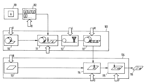
Fig. 1 shows the essential method steps during production and trans-
fer of embossed holograms to data carriers,
Fig. 2 shows the subdivision of the method sections shown in Fig. 1,
Fig. 3 shows the layer structure of a transfer band,
Fig. 4 shows the layer structure of a finished hologram on a sub-
strate,
Fig. 5 shows the production sequence in producing embossed holo-
grams and transferring them to data carriers,
Figs. 6 - 24 show various embodiments of individualized holograms,
and
Fig. 25 shows the production sequence in producing volume film ho-
lograms.
'viethod for producing transferred embossed holograms
Fig. 1 shows the essential stages in the preparation of embossed
holograms and their application to data carriers by the transfer method,
as are customary in the current technical state of the art. The method is
202642
thus divided into
- preparation of an embossing master (Pos. 1. Fig. 1 ),
- molding of identical die-plates (Pos. ~, Fig. 1 ).
- embossing the holograms on transfer bands (Pos. 3. Fig. 1 ), and
- transferring the holograms to the product (Pos. 4, Fig. 1).
The individual method steps are obviously so different from each
other technologically that they take place in completely different pro-
duction areas. Due to the complexity of these method steps they are
frequently even performed in completely separate industrial factories.
The transition from one production area to the other takes place at the
technological points of intersection at which the intermediate product
exists in the form of a predefined semifinished product.
Each of these four method steps indicated in Fig. 1 has its techno-
logical focal points. Thus. in step 1, the preparation of the embossing
master, photography or holographic technology is dominant. In this area,
that is comparable in structure with a film studio, are the objects to be
rendered holographically are produced as models (usually on a 1:1 scale).
the film material is exposed holographically, the holograms (films) are
copied onto different film material, developed, etc., and the first emboss-
ing masters are prepared. On the embossing master the hologram exists in
a fine surface relief structure that can be duplicated by mechanical em-
bossing in sufficiently smooth and deformable materials. Since when a
relief structure is embossed the relief is subject to high mechanical loads
and thus also high wear, one - customarily reproduces the holograms using
not the embossing master itself, but die-plates deriv ed from it. Since the
molding of die-plates from an original (embossing master) is also only
repeatable within limits, they are prepared in multistage methods via so-
called "submasters" or "sub-submasters," etc.
The die-plates are customarily molded from the embossing master, the
submaster or the like in galvanoplastic fashion. The necessary method
steps for this are well-known and need not be described here in any
detail. The only fact worth mentioning in this context is that the produc-
tion conditions required for this second production step (Pos. 2, Fig. 1 ) ,
are equivalent to those in the chemical industry. The production equip-
ment used in this method step consists primarily of galvanic baths in
which metal layers are produced, to render the master relief, in suitable
2026542
electrolytic solutions of metallic salts and chemical additives under the
action of electrical direct current.
when the die-plates exist they are used in the third method step
(Pos. 3. Fig. 1) in embossing machines to transfer the relief to plastics
surfaces, etc. In a variant preferred for the inventive method the relief
structures are embossed into standardized "transfer bands" that can in
turn be put in intermediate storage as semifinished products and used in
a great variety of ways on the subsequent "products."
It is fundamentally possible to apply the holographic relief to the
product in one- or two-step methods. In one-step methods the relief
structure of the hologram is emuossed directly onto the surface of the
product to be equipped with the hologram. Depending on the quality of
the product this procedure is impossible in many cases, however, since
embossing can only be performed on smooth deformable surfaces under
the action of high surface pressure. For this reason, but also due to the
higher flexibility, one thus generally selects the two-step method in prac-
tice, by which the relief is first produced on an intermediate medium, e.g.
a transfer band, and glued, sealed or similarly fixed to the product in
this form. Although the inventive principle can be used in both versions.
the two-step variant is preferred since this embodiment permits a greater
range of variation. This holds in particular when a transfer band is used
as the intermediate medium.
The transfer bands are likewise produced in several individual steps
depending on the required structure or the desired hologram quality and
security standard. In this process multilayer neutral foil strips are pre-
pared into which the holograms are embossed set up in a line. The em-
bossed strips are then given an additional coating to protect the Pine
relief structure from mechanical damage, but also from any manipulation.
This third method step (Pos. 3, Fig. 1 ) involves elaborate and complex
mechanical production machines due to the required quality and the fine-
ness of the structures to be produced. The technical equipment used in
this method step corresponds essentially to that customary in fine me-
chanics and in printing and plastics technology.
In the fourth step (Pos. 4, Fig. 1) the finished hologram a trans-
ferred from the transfer band to the subsequent product. In the present
case the product is preferably an identity card, paper of value, bank
note, etc. However, it is also useful and conceivable to transfer the holo-
gram to video tape cassettes, phonographic records, labels in the clothing
2o2s~~z
9
industry. etc. The transfer of the hologram is performed in highly auto-
mated production equipment. as in the third method step. But in contrast
to step three (Pos. :3. Fig. 1) the product-specific aspects, e.g. those of
paper of value or card technology, must also be included here. In order
to prevent the transfer from impairing the quality of the hologram and/or
product. the particular interacting parameters of the two elements. such
as e.g. properties of the material, processing temperatures. mechanical
stability under load, etc., must be accordingly taken into consideration or
coordinated with each other. Different products can thus necessitate very
different measures for applying the holograms. The transfer of the holo-
grams is generally performed either by the product manufacturer itself or
by contractors which produce the packaging. labels or the like for the
product.
The method blocks shown in Fig. 1 shall be explained in more detail
in the following with reference to Fig. 2.
Production of the embossing master
A three-dimensional model is generally prepared from the object to
be shown later, whereby the model must be on a 1:1 scale for the cur-
rently customary holographic techniques. The necessary method step for
this is marked by Pos. 5 in Fig. 2. When the model exists, a laser-recon-
structible hologram is produced on a silver-coated film in intermediate
step 6. This hologram, also referred to as the "primary hologram," is
then copied over to a second hologram film by the so-called "rainbow
technique" so that the holographic image can also be viewed in white
light (without a laser). The photosensitive material preferably used in this
copying operation is photoresist layers. This measure converts the holo-
gram present in the primary hologram as a halftone structure into a sur-
face relief. The thus produced hologram is customarily referred to as a
"secondary hologram." In the last intermediate step 7 of method step 1,
the "embossing master" is prepared from the secondary hologram in elec-
trogalvanic fashion, the holographic information existing in the master
likewise in the form of a surface relief.
Molding of die-plates
The embossing master produced in intermediate step 7 is an expensive
.. to
unicatP and is generally not used for embossing holograms due to the
danger of injury and of ~.cear. Instead. a two- or multistage method is
used to mold "submasters" from the master, again in electrogalvanic fash-
ion (intermediate step 8) and from them the actual die-plates (interme-
diate step 9). Starting with the master the submasters exist as negative
reliefs. From the submasters one prepares the actual die-plates as positive
reliefs. which are then used to emboss the surface relief into a plastic
material. The life of a die-plate is rarely more than 10.000 embossings,
so that a considerable number of such die-plates must be produced for
large runs.
Preparation of the transfer band
The transfer band has a multilayer structure and comprises at least
a carrier layer and an again multilayer embossing layer. The transfer
band is produced in several method steps, which are divided in Fig. 2 into
a preparatory step 10, hologram embossing step 11 and finishing phase 12.
In preparatory step 10 the carrier band is coated with an embossable
material in such a jcay as to allow for trouble-free separation in the
subsequent transfer operation under the action of pressure and heat. In
the simplest case this is obtained by providing a layer of wax between
the carrier band and the embossable plastics layer. In cases in which the
hologram is to be recognizable by reflection, a further metal layer with
high reflectivity is provided on or under the embossing layer.
In production step 11 the relief structure is pressed into the emboss-
able plastics coating with the- aid of the die-plates produced in inter-
mediate step 9. The thus produced surface relief is then covered with at
least one protective layer to protect the relief from mechanical damage.
This protective layer should be coordinated with the material of the em-
bossable layer so as to impair the optical properties of the hologram as
little as possible. For various reasons that need not be explained here,
further layers necessary for protecting the hologram are applied over the
first protective layer. The last layer provided is finally a heat-sealing
layer to ensure an unproblematic transfer and adhesion of the hologram
to the subsequent product.
11
202642
Transfer to the product
The transfer of the holograms to the product. e.g. cards, papers of
value or the like, takes place. as already mentioned, in method step 4.
As in the production of the transfer band, a neutral semifinished product
is also prepared here in an intermediate step 13. In the case of identity
cards this is the finished card blank, in which the printed card inlay is
already coated with cover foils and, if necessary, equipped with magnetic
stripes, signature stripes and the like. However, the card blanks existing
in this form usually do not yet exhibit the personal data of the subse-
quent card owner.
The hologram is transferred from the transfer band in intermediate
step 14, in which the hologram is positioned above the proper area in the
card and pressed onto the card with the aid of a hot press die in a
so-called "hot stamping machine." When the carrier band is removed the
multilayer structure containing the hologram tears precisely on the con-
tour line of the press die, thus coming off the transfer band. The card
thus equipped with a hologram is provided in intermediate step 15 with
the user-related data, for example by a laser personalization method.
The result of this production method is finished card 16 which, as
shown schematically in Fig. 2, is now equipped with a properly placed
hologram 1 i and data record 18 consisting of user-related and neutral
data.
Fig. 3 shows transfer band 19 in cross section. It comprises a carrier
band 20 to which a separation layer 21 of wax is applied. Thereabove it
has a protective layer 22 and a layer of thermoplastic material 23 which
is somewhat less thermosensitive than separation layer 21. Thermoplastic
material 23 is covered with a thin, weak metal layer 24 preferably con-
sisting of vacuum metalized aluminum and being at least less than 5,000
angstrom thick. When producing transparent holograms one dispenses with
metal layer 24. Layers 20 to 24 are a semifinished product (raw band)
into which the relief structure is embossed.
To emboss in the surface relief pattern, one presses a heated ~ die-
plate onto metal layer 24. Under the action of heat and pressure, ther-
moplastic material 23 gives way so that the relief pattern is embossed .
into aluminum layer 24. ~ second protective layer 25 and a heat-sealing
layer 26 are then applied to metal layer 24. In special variants, layers 25
and 26 are also combined into one layer. The thus produced material is an
2026542
12
intermediate product which can likewise be stored and transported easily
as a semifinished product.
For application of the hologram to the product, transfer band 19, as
shown in Fig. 4, is placed with heat-sealing layer 26 on a substrate 30,
for example a card, and pressed onto it. The pressing is performed with
a heated transfer die 34 or alternatively with a transfer roll. Under the
action oP heat and pressure, heat-sealing layer 26 bonds with substrate
30. Simultaneously separation layer 21 melts, allowing for removal of
carrier material 20. The bond with substrate 30 and the separation of
carrier 20 take place only in the surface areas in which separation layer
21 is heated, i.e. only exactly below transfer die 34. In the other surface
areas the layer structure and the carrier material remain firmly inter-
connected. Since layer structure 22 to 26 tears along the contour edges
of transfer die 34 when the carrier film is removed from the substrate,
the contour of the thus transferred hologram always corresponds to the
contour of the press die, whereby more complicated contour structures
can also be realized in this way. The process of heat-sealing is known,
however, and is described for example in German "offenlegungsschrift" no.
33 08 831.
Individualizing measures with transferred embossed holograms
Fig. 5 again shows the entire production sequence for producing a
hologram and applying it to a data carrier together with possible individ-
ualizing measures in a flow chart. In contrast to the view described in
Fig. 2, method steps 1 to 4 shown in Fig. 5 as simultaneous production
processes, as is customary in practice, whereby essentially only those
method steps are referred to which are particularly suitable in the sense
of the invention for individualizing the standard hologram. For better
comparability, the same positions are marked here by the same position
numbers.
The inventive possibilities of intervention for individualizing em-
bossed holograms are shown in Fig. 5 by arrows labeled A to G.
Possibilities of intervention are thus given
- during production of the die-plates (A),
- during preparation of the raw band (B),
- during completion of the transfer band (C),
2026542
13
- on the finished transfer band (D).
- during preparation of the substrate (E),
- during transfer of the holograrn to the substrate (F),
- on the final product (G).
In the following, the various possibilities of intervention A to G shall
be explained.
Individualization variant A (during production of the die-plates)
The die-plates are generally produced by galvanic copying of the
relief structure. There are various equivalent one- or multistage methods
for doing this. In a frequently applied two-step process a hardenable
plastics compound. such as for example an epoxy resin, is applied to the
surface of the master. After hardening the plastics is separated from the
master, resulting in a negative mold of the relief structure. By electro-
plating a nickel layer is applied to the negative mold. This nickel layer,
which is a positive copy of the master, is the basis for the further
production of the press die.
One can give the subsequent holographic image an individual appear-
ance, as shown in Fig. 6, by transferring only selected surface areas of
the master during molding. This is done by transferring the subsequent
holographic image to the die-plates only in the outline of the area of a
letter, a numbering, a company mark or the like, or by pretreating the
die-plates in such a way that the relief structure is only formed onto this
area of the press die.
There are thus a great number of equivalent approaches for producing
the individualized hologram shown in Fig. 6. In a special variant, certain
surface areas of the master are covered by means of photolithography. A
positive-acting photoresist lacquer is applied for this purpose to the sur-
face of the master. It is then exposed via a mask in which the shape of
the letter or company mark is left open. During development of the lac-
quer the exposed surfaces are laid bare while the unexposed surfaces
remain covered. The press die is molded from this individualized master
in the known way, whereby the holographic relief structure is transferred
only in the surface areas left open.
The example of Fig. 6 shows an embossed hologram 40 finished in
this way. In contrast to standard hologram 41, the relief structure or
202542
14
holographic information is present in embossed hologram 40 only in a
selected surface area 42, symbolized by the letter H. In remaining surface
areas -13 one can see only the unembossed surface of the metal layer, so
that the holographic information stands out from altogether reflective
surface 40 in area .12 in visually recognizable fashion at certain viewing,
angles.
The master can also be used repeatedly to produce individualized
copies if the covered ranges are laid bare again using suitable solvents
and the individualization operation repeated with other masks.
The method can also be applied in the same way to submasters or the
die-plates themselves.
For the die-plates, irreversible methods can also be used due to their
limited life in contrast to the embossing master. For individualization the
relief structures can, for example, be removed or changed in certain areas
by chemical or fine mechanical processes. It is also possible to remove or
destroy the relief structure selectively using fine mechanical devices.
The die-plates individualized in this way can be used to emboss a
few thousand individualized holograms per plate. If greater piece numbers
are required. several die-plates must be individualized in identical fashion.
Individualization variant B (during preparation of the raw band)
The production of the transfer band takes place in several phases.
In the preparatory phase a raw band 28 shown in Fig. 7 is first produced.
For this purpose a separation layer 21, then a lay er of protective lacquer
22 and finally a thermoplastic layer 23 are applied to a carrier material
20, e.g. a polyester foil. A metal layer 24 is customarily vacuum metalized
onto the uppermost layer if the subsequent embossed hologram is to be a
reflection hologram. For transmission holograms, metal layer 24 is omit-
ted. The layer structure thus described constitutes raw band 28.
The raw band is individualized by appropriate modification of the
layer structure, either by varying the layers themselves, e.g. providing
different coloring or changing one or more of these layers, or by selec-
tively introducing additional elements, e.g. printed patterns which are
superimposed on the standard hologram in visually recognizable fashion in
the final state (on the subsequent product).
For industrial scale production of standard holograms one requires a
large number of raw bands. By appropriate modification of the layer
2o2s~4z
structure one can already. ,.vithout any further technical measures. pro-
duce standard holograms that differ very substantially in terms of both
their color and their overall impression. These measures can relate either
to individual raw bands or to batches of raw bands.
:~ first variant for individualizing raw bands is to dye the layer of
protective lacquer 22 and; or thermoplastic layer 23 individually. Since
these two layers later come to lie on the product above the relief struc-
ture, as shown in Fig. 8, one preferably uses transparent colors for this
purpose. It is thus possible to distinguish such individualized holograms in
the finished product, e.g. card 30 (Fig. 8), by their own typical color
effect.
In another variant, various metals 24 with different inherent colors
are vacuum evaporated on thermoplastic layer 23. Using copper, silver or
gold, for example, one can prepare three different-colored types of holo-
gram with these metals. The color of the metal layers can thus be coor-
dinated quite selectively with the _overall color impression of the card
layout, and used for example to mark cards with different scopes of en-
titlement.
In a third variant, an individualizing printed pattern is applied to one
of layers 22, 23 of the raw band by conventional printing techniques.
Suitable printing techniques are offset printing, silk screen printing or
other known techniques. For a small-lot individualization the printed
pattern can remain unchanged over a certain number of holograms, this
printed pattern being preferably coordinated with the holographic image
so that it constitutes a border, a central motif or the like for the holo
graphic information in' the sense of a graphic composition. The overall
impression of such an individualized hologram is thus determined in the
_ final state by the holographic recording and the printed pattern equally.
In a further variant, the printed pattern is equipped with patterns or
data that vary from hologram to hologram. An example of this is a con-
tinuous numbering, which can be produced using a number printing unit
or the like.
If the printed pattern is to appear on the subsequent data carrier in
a certain alignment to the hologram, one must make sure the printed ,
pattern and the subsequent hologram are designed so as to register , ex-
actly one upon the other. For work in exact register one can use the
measures known in printing technology, such as marginal perforation,
register marks and the like.
~~p2~~4
16
The great number of possible variations include the use of different
printing techniques, dyes, inks and metalized layers to produce certain
optical impressions and realize special forms of individualization. One
must also specially mention in this connection the use of luminescent, or
phosphorescent substances, which may make special individualizing meas-
ures recognizable only in special illumination.
Figs. 7 to 9 show an embossed hologram 17 that is equipped. as de-
scribed above, with an individually printed layer of protective lacquer 22.
Printed pattern 2 7 was applied to the surface of layer of protective lac-
quer 22 and then covered with thermoplastic layer 23 and provided over
this layer with a metal layer 24. As already described, the relief struc-
tures of the hologram are embossed onto this raw band 28. After further
layers 25, 26 are embossed. the production of the transfer band is com-
pleted.
Fig. 8 shows such an individualized layer structure as it is disposed
on a subsequent product, a card 30. According to this representation,
printed pattern 27 is now disposed over metal layer 24 and thus also
over the relief structure of the - hologram. The normal viewer thus sees
printed pattern 2 7 as printed information independent of the viewing
angle that is disposed on a background with metallic luster on which
holographic information 29 is recognizable over a large area within a pre-
defined angle range. Printed pattern 27 shown in Fig. 9 has both data 47,
which remain the same in the series of the individualized hologram, and
data 48, which vary from hologram to hologram.
Individualization variant C (during completion of the transfer band)
In next production phase 11 the holographic relief pattern is em-
bossed under the action of heat and pressure into vacuum metalized
layer 24, whereby the embossing and the metalizing can of course be per-
formed in reverse order depending on the production method. In final
phase 12 a protective lacquer 25 and an adhesive layer 26 located thereon
are applied to the embossed side of the laminar compound. A cross sec-
tion through finished transfer band 19 is shown in Fig. 3. ' ,
For individualization, an individualizing printed pattern can be pro-
vided in method step 12 directly on embossed metal layer 24 or on pro-
tective layer 25, which is then covered by hot-melt adhesive layer 26.
The printing methods and printed patterns can be similar to those in
202642
1;
individualization variant B. Ho~.vever, one must mal.:e sure that the print-
ing operation does not damage the relief of the hologram present in
embossing layer 23. 24.
?, transfer band produced in this way is shown in Fig. 10, whereby in
this embodiment the printed pattern is present between hot-melt adhesive
layer 26 and protective layer ?5.
.after the hologram has been transferred to the card body, the print-
ed pattern comes to lie between card body 30 and metal layer 2~ as ap-
parent from Fig. 11. Since printed pattern 2 ~ is now disposed for the
viewer below reflective metal layer 24, special measures are necessary to
make this printed pattern recognizable visually or by machine.
It is obviously easiest to make printed patterns applied after relief
embossing visible if one dispenses with metal layer 24 in the hologram
structure. In this case one speaks of a "transmission hologram," which can
also be very useful thanks to corresponding measures, that shall be dis-
cussed in connection with individualizing measures E.
Instead of complete omission one can also reduce the layer thickness
in the range of a few tens of angstrom to obtain a partial permeability
that makes the printed pattern recognizable with sufficient clarity. By
using special metals one can achieve an- additional color effect since var-
ious metals, when they exist in extremely thin layers, exhibit different
color effects in incident light and transmitted light.
Alternatively, one can vacuum metalize a dielectric layer instead of a
metal layer. Depending on the layer structure, such layers have special
spectral properties that can likewise be utilized in transmitted and inci-
dent light. Examples taken from the numerous optical forms are partly
permeable wide band mirror coatings and spectrally close reflection bands
with a play of colors when the viewing angle is changed. In these vari-
ants the printed pattern is likewise recognizable only at certain viewing
angles. In a further variant, metal layer 24 is designed as a fine screen
composed, for example, of metallically reflective and transparent areas
located side by side. The transparent areas are preferably given a screen
width in the range of 1/10 mm and less, so that the screens cannot be
resolved ~ by the eye and appear as a homogeneous partly reflective sur- ,
face despite their gaps. In this case printed pattern 27 is recognizable at
every viewing angle. In cases in which printed pattern 27 is to be utilized
_. solely for automatic detection it .is useful, in a further embodiment, to
employ dielectric layer structures that act reflectively in the long wave
18 202~~42
spectral range but are transparent in the short wave range. If the filter
edge is set at the boundary between C~V light and visible light, the mark-
ing remains hidden from the eye but is identifiable for a UV-sensitive de-
tector.
Similarly, one can obtain hologram w riting that is readable only in
the infrared range if metal layer 2.i is designed as an IR-permeable layer.
It is covered, for example, by a protective lacquer 25 that appears
opaquely black in the visible spectral range and is transparent and partly
permeable in the IR range. Printed pattern 27 consists in this case of an
IR-reflective color and is located, as described above, between layer of
protective lacquer 25 and adhesive layer 26. On the subsequent card the
holographic image is clearly recognizable visually against the partly
metalized apparently black background. At the same time, IR printed pat-
tern 50 shown by the broken lines in Fig. 12 is readable using suitable
sensors.
Depending on the design of the printed pattern, one can also realize
here a marking that is unchanged for a predetermined run or varies con-
tinuously. If printed pattern 27 is designed as information that is readable
in the nonvisible spectral range, it can also - be further optimized for
these needs if it is designed not as alphanumeric writing, but as machine
code, e.g. in the form of a bar code or the like.
A further possibility of individualization by which the form of the
hologram is varied is to structure adhesive layer 26 accordingly during
completion of the transfer band. The adhesive layer is applied to the
laminar compound here in the form of a pattern. During the transfer to
substrate 30 only those areas can adhere to substrate 30 which are coat-
ed with hot-melt adhesive layer 26 even if the action of pressure and
heat through the hot press die covers a large surface. Depending on. the
shape and surface area of hot-melt adhesive layer 26, only predefined
areas of the hologram are thus transferred selectively, possibly even
independently of the shape of the press die. This method is a particularly
favorable variant of individualization since it is to be provided in the last
operation during production of the transfer band and can thus be added
in a relatively late stage of the production of the transfer band. Since
the transfer band can be put in intermediate storage as a semifinished
product without adhesive layer 26, this variant likewise permits transfer
bands that are in storage to be individualized in any desired number of
units at very short notice.
202542
19
Individualizing measure D (on the finished transfer band)
After final completion of transfer band 19 shown for example in Fig.
3, there are various other possibilities of individualization. Individualiza-
tion in this stage of the method is particularly favorable since the trans-
fer band exists in this embodiment as a finished intermediate product, on
the one hand, and is protected relatively well from damage by the pro-
tectiv a layers present in this stage of the method, on the other hand.
The individualizing measures are based primarily on the inscription of
individual data in one or more layers of the transfer band, or on an
irreversible transformation or removal of the layer material.
Data can be inscribed using laser inscription. A laser inscriber is used
to produce, through carrier sheet 20 or layer of protective lacquer 26,
irreversible changes or destruction in the layer structure, such as e.g. a
blackening, a destruction of the diffraction structure. a removal of the
metal layer, etc. Depending on their position in the layer structure, the
inscribed patterns are directly visible on the finished hologram card or
concealed under metal layer 24.
Laser inscription is based on the absorption of the laser radiation by
the medium to be inscribed. It has been found that customary reflection
holograms are generally very suitable for such inscriptions. In cases in
which the laser inscribability does not suffice, which can be the case in
particular with transmission holograms, it is possible to improve the
inscription quality by adding absorbent colors or additives to one or
more layers of the transfer band. In this way one can also sensitize spe-
cial layers of the transfer band in a particular .way so that these layers
can be influenced more selectively if the laser energy is dimensioned
properly.
At high laser power, the low thickness of the individual layers gen-
erally leads to complete vaporization of the material or plasma formation
through the total layer structure. In this way one can obtain inscriptions
of the transfer band which, regardless of the side to which they are
applied, are always clearly recognizable on the finished product and can-
not be changed later. This aspect is of special interest in particular if
the introduced data are to exist in an unforgeable form.
As an alternative to laser inscription there is also the possibility of
providing mechanical perforation in the transfer .band- (Fig. 13). For this
purpose the foil in the area of the hologram is furnished with structured
202~~42
~0
perforations using a kind of matrix; printer. or with a punched pattern
that is produced by a firmly set punching die. For particularly compli-
cated perforations, that may also vary from hologram to hologram, it is
also possible to use engraving machines that remove material with the aid
of an X-Y controlled gray ing tool.
The apparatus that can be used for laser inscription or the mechan-
ical removal of material is known to the expert and need not be ex-
plained in more detail here.
Individualizing measure E (during preparation of the substrate)
One can obtain further effects by performing selective measures on
the substrate which are compatible with the hologram used. For this pur-
pose, markings are applied in the hologram area to the surface of the
substrate, which are later covered wholly or partly by the hologram and
are recognizable therethrough.
Figs. 14 to 16 show a first variant of these measures in cross section
and in a front view. Fig. 14 accordingly shows a card 30 provided with a
printed pattern 60 over which a transfer hologram i7 was disposed. Print-
ed pattern 60 is only partly covered by hologram 17 so that the informa-
tion represented by printed pattern 60 is only partly accessible. Fig. 15
shows the card shown in cross section in Fig. 14 in a front view. If a
transparent hologram is used, the data disposed under hologram 17 are
still equally recognizable, since the hologram is approximately equivalent
to a transparent sheet at the viewing angles at which the holographic
effect is absent. In spite of their recognizability the data located under
hologram 17 are protected from access or manipulation by hologram 17
thereabove. In this way important information of a card can be visually
checkable but removed from direct access, whereas less important data
remain freely accessible. The data located under the hologram can thus be
directly related to those located outside, have the same or a similar in-
formation content or relate to completely different matters. The use of a
reflection hologram furthermore also prevents visual accessibility, so that
data 60 located under hologram 17 can only be checked by machine. ,
The data carrier may be a great variety of materials, e.g. the inlay
of a multilayer card structure, an all-plastic card blank or a packaging
element or the like. The _ individualization _~rariant is particularly
effective
if the printed pattern is disposed on the substrate in such a way that the
2026542
21
hologram to be placed thereabove, as shown in Pig. 1:1, comes to lie
directly above the printed pattern. In this way one obtains not only the
possibility of various designs but also a protection of the data located
under the hologram, since these data cannot be changed or removed with-
out destruction of the hologram. Such data protection is particularly
effective in papers of value, for example, whereby particularly important
data of the paper of value can be optically emphasized ~by their super-
position with a hologram, on the one hand, and protected from access, on
the other.
Just as in the previous variants, printed pattern 60 can represent a
motif, a company mark or the like that remains unchanged through a
large number of data carriers, or contain information that v aries from
data carrier to data carrier, such as continuous numbering. After printing,
hologram 17 is placed on the data carrier. Depending on the hologram
design, the recognizability of the printed pattern varies. Transparent or
partly transparent holograms allow the printed pattern to be recognized
visually. IR- or UV-permeable holograms should be provided for hidden
inscriptions to be read only by machine. Possibilities for designing partly
or fully transparent IR- andior UV-permeable holograms were already
mentioned in the above description and can also be used here.
In a further variant shown in Fig. 1E, a background with metallic
luster is applied to data carrier 70 in the hologram area as printed
pattern 7 2, which represents a coat of arms in the present case, but may
also be a company logo, character or similar mark. On the thus prepared
data carrier a hologram is placed that either contains no reflective layer
or is equipped with a partly reflective metallic mirror through which the
shiny surface remains recognizable. The mark thus supplements the holo-
gram or at least remains visually recognizable through the glued on holo-
gram, whereby printed pattern 72 dominates if transparent holograms are
used, and holographic information 71 of standard hologram 70 predomi-
nates in terms of the optical impression if semipermeable holograms are
used.
In a further variant,which is shown Figs. 17 and 18, standard
in
hologram 17 is used a paper of value which it forms a kind
in in of
translucent printed information.
register together Paper
with steel
intaglio
of value 75 is furnishedwith a steel intaglioprinted pattern 77,
that is
known to have a positiverelief on the ink e and anegative relief
sid 78
on the back the inking. Hologram17 is applied to the
congruent back
to
2026542
of the paper of value in the area of the steel intaglio printing, ~.shereby
negative relief .8 is still apparent after the large-surface transfer of the
hologram. since the latter has no inherent. strength so that adhesion of
the hologram was prevented in the area of the depressions. In the surface
of hologram 17 the steel intaglio information therefore exists as an inter-
ruption in the hologram. In the present case it is possible to compare the
identity of printed pattern 77 with recesses 78 both by viewing the front
and back of paper of value 75 and in transmitted light, since in this
case printed pattern i . is recognizable through the paper and can be
detected congruently in the hologram recesses in the unfalsified original
case.
In a variant of the method described in Figs. 1 ~ and 18, the hologram
can of course also be applied to the front of the paper of value, as
shown in Fig. 19, whereby in this case only the apexes of the steel in-
taglio relief are coated with corresponding patches of hologram 17. This
measure is particularly effective in combination with a so-called "blinding"
or a blind stocking, since in this case inking 77 is omitted and thus only
the hologram covers the relief structures.
The variants described in Figs. 17 to 19 are particularly advantageous
since the hologram is always transferred to the relief of the data carrier
congruently in a particularly simple way, and such applications (st.eel
intaglio printing or blind stocking) fit particularly well into conventional
paper of value designs and can also be integrated particularly easily into
the classical production methods.
Individualizing measure F (during transfer of the hologram to the sub-
strate)
In this method step the hologram is transferred from the transfer
band to the substrate by means of a heated transfer die. The transfer
takes place only below the immediate contact surface of the transfer die.
After removal of the transfer die the hologram tears along the edges of
the contact surface when the transfer band is removed. The hologram
adhering to the substrate thus has the exact contours of the transfer die. ,
In this method step the holograms can be individualized by selectively
varying the contour of the contact surface of the transfer die. The holo-
- gram . is-- thus given the same individual contour as the press die. In.
this -
way the holograms can be designed in the form of special motifs, com-
202642
23
t any logos, characters and the like. The motifs arp to be represented
both in the positive print and in the negative print. Fig. 30 shows sche-
matically such an application, whereby original standard hologram 17 was
actually transferred by the press die only ~c~ith the external contour
shape of a circle 80, whereby a set of lines 81 is left open inside this
circular area in the form of a coat of arms. Shaded surface areas 82 of
original standard hologram 1 i are disregarded during the transfer.
The expert will understand that this variant makes it possible to
transfer almost any piece numbers of individualized holograms by pro-
ducing only one hot press die. The graphic structures can also be of
substantially more elaborate design and can even replace or supplement
w hole areas or parts of the printed pattern. The transfer dies can be
designed in such a way as to represent not only simple pictorial symbols
or characters, but also complicated systems of lines or guilloche struc-
tures. If skillfully designed, such a "hologram embossing" can be used in
as versatile a way as .a printing ink. Such an application integrates the
hologram into the overall printed pattern less "obtrusively" and can also
be used in cases In which large-surface hologram representations were
previously not usable for esthetic reasons. When integrating such "holo-
gram structures" one must merely make sure the holographic effect and
the holographically rendered details decrease in proportion with the re-
duction of the hologram surface. Complicated holographic information can
thus not be rendered as well in holograms present only in line areas.
In a further variant of these individualizing measures the transfer
die is replaced by a matrix hot stamping device. These commercially
available devices make it possible to change the shape of the die perma-
nently in the transfer phase, so that contour structures varying from
hologram to hologram can also be -produced in this method step.
Individualizing measure G (on the final product)
In this method step the hologram transmitted to the substrate is
modified by punctiform removal, change or destruction in suitable layers.
A first variant is individualization by inscribing information using a
laser pencil. Depending on the laser parameters and the foil structure,
various inscription effects can be obtained that are based on the manifold
interaction of the laser beam and the hologram structure. In . this way one
can obtain both unobtrusive material and color changes in the layer
- 202~~42
structure of the hologram, and the local destruction or complete removal
of certain areas of the layer structure of the hologram.
Fig. 21 shows a card body 30 in cross section in connection with two
exemplary inscription variants. Hologram 17 is not only totally destroyed
by the high energy of the laser beam. but the card substrate is also
deformed in such a way that a microrelief 85 exists in this punctiform
area. The card substrate is customarily burned locally in such laser in-
scriptions, so that the inscribed area has a black color ensuring good
readability of the thus produced characters. The microrelief provides an
additional authenticity criterion that distinguishes original laser inscrip-
tions from other inscription variants.
By correspondingly reducing the laser energy, however, one can also
only remove the hologram layers locally, so that in the extreme case the
data are formed by recesses 86 in the hologram. In principle, the same
technical possibilities are applicable in this individualization measure as
are described for measure D. In contrast to individualization on the fin-
ished transfer band (measure D), however, the forms of individualization
stated here are applied to the -finished product, which basically allows for
individualization of any- hologram. This is especially advantageous in par-
ticular when the technical method is employed for the individualizing
measures that is also used for providing the personalization data of the
card. Precisely for this reason it is particularly recommendable to use a
laser inscription system. In principle, however, other methods are also
applicable. One must merely make sure the individualizing measures act
on the hologram in irreversible fashion so that they cannot be undone.
Combination oP individualizing measures
The above-described individualizing measures A to G allow for a
hologram individualization in the very different steps of die-plate produc-
tion, transfer band production and product manufacture, whereby each
single measure offers a very great scope of design and has its own char-
acteristic form for the particular method step. Starting with a standard
hologram one is thus shown very different ways of making changes for ,
producing very different holograms despite the use of the same embossing
master. These holograms in the final product allow not only for individual
characterization, but also for the protection _ of data.. 1-ocated on . the _
product.
2~ 2026~4'~
It is obvious to the expert that individualizing measures A to G can
not only be used separately per se, but that any desired combination of
individual measures will additionally increase the possibilities of design.
By way of example for the great number of possibilities, some variants
shall be stated in the following, whereby the reference numbers of the
preceding examples have been used wherever possible.
Fig. 22 thus shows an individualized hologram 17 in which holographic
information 39 exists across the entire surface of rectangle 70 but re-
flective metal layer 24 is present only in the form of a coat of arms
(individualizing measure B). In the area of the coat of arms there is a
printed pattern 27 (measure B) and hologram-specific data 85 inscribed
with a laser pencil on the finished product (measure G). The outer pro-
tective layer oP the hologram is yellow (measure C) so that the coat of
arms appears yellow to the viewer. The hologram is applied to a blue
area 60 that is printed on the product (measure E).
The described embodiment appears to the viewer in the area of the
coat of arms as a yellow tinted hologram that clearly shows the desired
holographic effects at certain angles. The hologram areas surrounding the
coat of arms appear green (the secondary color from blue and yellow),
whereby the holographic information is also recognizable in this area,
although less trenchantly. The apparently greenish yellow rectangular
hologram field is limited by a blue frame that has no holographic effects
but supplements the color of the holographic representation.
Fig. 23 shows a further embodiment in which an individualized holo-
gram 42 is used that has the contour shape of a circle standing on a
rectangular bar. The shape of hologram 42 is embossed by the contour
shape of the hot press die (measure F). In the area of the rectangular
bar there are numerical data that were produced by means of .a laser
pencil and exist as recesses in the hologram area (measure G). In the
circular area of the hologram a printed pattern 27 is provided in the
form of the letter "A," that was provided with light blue ink during the
completion of the transfer band (measure C). Silvery metal layer 24 pres-
ent in the contour is disposed above printed pattern 27 as a semiperme-
able mirror. The entire layer structure is located on a yellow background ,
print 60 that is provided on the card substrate (measure E).
This hologram structured in its contour appears to the viewer as a
silvery surface Lhrough which blue. printed pattern 3 7 is recognizable. In
a given viewing angle range the holographically stored information, which
~6 2026542
is also superimposed on printed pattern 3. , appears in total surface :12.
Only numbers 86 are recognizable in good contrast with the surroundings
regardless of the viewing angle. The overall arrangement is framed by the
~-elloS.~ background area.
Fig. 24 shows a further embodiment in which a paper of value is
equipped with a translucent element. The paper of value is provided with
a printed pattern 101 applied by steel intaglio printing (measure E). On
the back of the paper of value a transmission hologram is applied in the
circular contour of printed pattern 101, in which the contours of printed
pattern 101 are left open (measure F). The hologram itself is designed as
a transmission hologram in which no metal layer is provided and the two
outer protective layers (layers 22, 23) are colored transparent red (meas-
ure C).
For the viewer the translucent element consisting of two parts is
recognizable from the front as a steel printed motif 101 and from the
back as a red colored. hologram with negative contour 101 left open. In
transmitted light the two elements supplement each other in such a way
that printed pattern 101 on the front fits into the recesses of the holo-
gram without a gap.
Individualization of volume film holograms
As mentioned in the introduction, the inventive individualizing meas-
ures are particularly useful for transferred embossed holograms and can
be integrated well into the production process. However, the inventive
application is not limited to this type of hologram. In the following the
utilization of the inventive ideas shall be described in connection with
volume film holograms.
The essential stages in the series production of volume holograms
include
- the preparation of a primary hologram,
- the reproduction of the holograms by copying,
- application of the holograms to a substr ate. ,
With reference to Fig. 25 the method steps shall be explained in more
detail in the following, whereby only the deviations of the two methods
will largely be dealt with on the basis of the details stated in Fig. 2 and
~; ~o2s~4,
Fig. 5.
In method step 101 a hologram is recorded from a model on a photo-
sensitive material. This is done by customary technology, superimposing a
reference ray with an object ray on a photographic plate. after develop-
ment and fixation this photographic plate represents the primary holo-
gram.
From the primary hologram. that corresponds to the embossing ma-
ster, one could now make any number of copies without requiring the
intermediate submaster step necessary for the embossed hologram, since
the copying of the secondary holograms is a strictly optical process that
does not load the primary hologram mechanically.
In particular if large amounts of copies are to be prepared from the
primary hologram at different times, however, it is recommendable to
avoid damage of every kind, in particular scratches, etc., by preparing
secondary holograms from the primary hologram as working specimens, _
which are then used for the subsequent exposure of the final hologram
film in method step 111. .
The secondary holograms are prepared by conventional technology in
intermediate step 102 in a way that is approximately comparable to the
production of the submasters or the die-plates (Pos. 2, Fig. o) except that
no photoresist material is used, but customary hologram films.
In intermediate step 110 the Pilms required for the volume hologram
are prepared. Holographic films consist, as is customary in photography,
of at least two layers, namely a carrier material, e.g. a polyester film,
and a photosensitive emulsion.
In method step 111, a film fabricated in this way is exposed precisely
as in method step 102 for producing the hologram to be used on the -
product. This is done in the known- way by employing the original holo-
graphic structure that was utilized in exposing the primary hologram,
except that the object is now replaced by the hologram film. A conju-
gated reference ray (reversed in time and direction) is directed onto the
secondary hologram. This produces a real image at the original position
of the object. With the aid of a second reference ray the virtual image
is recorded on the hologram film. By automatically repeating the copying ,
operation one can thus prepare any number of holograms in series pro-
duction.
After exposure the film is developed and fixed in intermediate step
112. Additional layers, such as a protective layer, adhesive layer, etc.,
~8 2020~~
can also be applied.
Intermediate step 11 ~ is prop ided for any measures on the finished
film. It is completely analogous to the processing of the embossed holo-
gram transfer band.
The substrate is prepared in method step 113. These measures are
also analogous to the embossed hologram.
In method step 114 the hologram is applied to the substrate. Depend-
ing on the substrate and the purpose, there are different possibilities of
attachment for fixing the hologram to the substrate. Common techniques
in this connection are to glue it onto the substrate or to laminate it into
the layer structure of multilayer substrates, such as identity cards. In
any case the hologram is punched out of the film and placed on the sub-
strate.
The final product is processed in method step 115. The measures
performed here are analogous to the steps necessary for embossed holo-
grams.
Individualizing measures for volume film holograms
The individualizing measures to be used for individualizing volume
holograms are likewise very similar to those described in connection with
embossed holograms.
First possibilities (measure H) are thus given in method step 102, in
which the holographic copy is given an individual appearance by inserting
masks or reproduction systems at a suitable place in the beam path, so
that the holographic image is accordingly changed or only recorded on
the hologram film in selected surface areas. In this way one can give the
holographic image a particular contour shape, for example that of a block
letter, or leave out such a shape from the holographic image. Since the
duplication of the holograms in method step 111 is essentially equivalent
to the measures in method step 102, the same or similar measures are
also possible in individualization variant I.
During production of the holographic film (intermediate step 110),
individualizing measures are possible in analogy to common photography ,
by coloring the carrier material or the emulsion layer with suitable dyes
or providing additional dyed layers above or below the carrier material.
It is likewise possible to print the film material on one or both sides in
this individualization variant K. Since when volume holograms are used
202542
29
the film layer is customarily applied to the subsequent substrate (product)
together with the carrier material, it is also conceivable to mark the
carrier film correspondingly. An additional individualizing measure when
preparing the holographic film is to preexpose the film with suitable
picture motifs, such as numbering, a logo or the like.
For individualizing measures L, M, N, O, P reference is made to the
measures described in Fig. 5 due to the analogous possibilities. Due to the
different holographic film material, some adaptations might be necessary.
If the basic inventive idea is known, these adaptations will be clear to
the expert and need therefore not be explained here.
As the expert will also understand, the various individualizing
measures H to P can be combined with each other as one pleases to
obtain more complex modifications.
Range of application
Individualized holograms have a wide range of application that will be
distinguished in the following in terms of how the holograms exist on the
subsequent final product. It is common practice to apply holograms to the
surface of data carriers. The data carriers can have a paper surface, as
do bank notes, identity documents, papers of value and the like, or else a
plastics surface, as do identity cards, plastics bank notes, video tape
cassettes, etc. In special embodiments the hologram can be limited to
certain parts of the product, while in others it covers the entire surface
of the product. In the field of identity cards and credit cards these
different variants have now become common practice. However, holo-
graphic elements can also be embedded in the products. It is thus known
to laminate holograms into multilayer plastics cards. The hologram can
exist in manifold embodiments, for example as a safeguarding thread, in
the form of a logo, an integrated picture motif or the like. It can also be
introduced by a kind of mounting technique by which an opening is pro-
vided in a foil layer of a multilayer card for the hologram to be glued
into.
It is likewise possible to embed holographic elements directly in
paper, whereby the holographic material is preferably prepared by being
cut into bands, stripes or planchets. These elements should preferably be
added during production of the paper, whereby the protection technique
is particularly effective if it is present in the paper in the form of a
202652
"window safeguarding thread," for example.
Due to the high number of possible variations, the invention gives
the expert the possibility of adapting the final product exactly to the
technical and/or design-related needs starting with a standard hologram.
Although like holographic recordings are used as the starting basis, the
invention provides possibilities of giving the final products completely
different getups. Along with the large number of possible optical varia-
tions, the inventive teaching also takes account of the financial require-
ments, so that it is possible to adapt the product to almost all require-
ments.