Note: Descriptions are shown in the official language in which they were submitted.
2U2~~~4
-1-
47-17775/=
Device for inZecting the light energy of a laser beam into a fibre-optic
optical wave~uide
and a method for adjusting and monitoring the position of the end of the fibre-
optic
optical wave~uide
The invention relates to a device for injecting the light energy of a laser
beam into a
fibre-optic optical waveguide, of which the end that is illuminated using a
focusing lens
arrangement has an end face extending at right angles to the longitudinal axis
of the fibre
and is fastened to a holding means capable of being positioned along three
axes. In
addition, the invention relates to a method for adjusting and monitoring the
position of the
end of a fibre-optic optical waveguide that is illuminated by a laser beam for
feeding in
light energy, which end is clamped in a holding means capable of being
displaced in three
axial directions and is illuminated by way of a focusing lens arrangement.
It is known to feed a laser beam with the aid of a focusing lens arrangement
into the end
of a multimode fibre-optic optical waveguide. In doing this it is necessary
for the
arrangement to be adjusted so that the laser beam meets the end face of the
core of the
fibre-optic optical waveguide to avoid the surroundings of the waveguide
becoming
heated owing to a faulty optical adjustment, which, owing to the high
temperatures that
occur, would lead to damage to the optical waveguide end and to its cladding.
Repair of
optical waveguide ends damaged in this manner, especially when a laser is
being used in a
clinical situation, can be earned out only at great inconvenience and with
difficulty. To
adjust the optical arrangement it is known to train light on the output end of
the optical
waveguide directed away from the laser in order to illuminate the end face of
the optical
waveguide directed towards the laser.
The invention is based on the problem of producing a device for injecting a
high-output
laser beam that can be reliably adjusted in a simple manner. This problem is
solved in
respect of the device by the characterizing clause of claim 1 and in respect
of the method
by the characterizing clause of claim 2.
The invention is based on the knowledge that a part of the light energy
injected into the
end face of the optical waveguide is reflected at the end of the optical
waveguide remote
CA 02026594 2002-06-19
21489-8095
-2-
from the laser beam and illuminates the end face facing the
laser from the inside of the optical waveguide. It is
therefore possible to r~=produce the end face on a screen
with the aid of a reproducing lens system; during a
reproducing process of t~izis kind, the light spot that the
laser beam generates on the end face of the optical
waveguide is reproduced simultaneously. In the device
according to the :invention and the method according to t:he
invention, after the be<~m splitter has been introduced and
the optical waveguide end has been adjusted, there is
produced on the screen ~~urface first-iy an image of the end
face and secondly an ima<3e of the light spot, so that with
the image of the end face sharply focused it is possible
within this image to di~7place the image of the light spot by
actuating the holding means that is adjustable in three
axial directions. The image of the brighter light spot
remains stationary on the screen, whilst the image of the
somewhat less bright anc~ larger end face is radially
displaceable. By disp:lac:ing the optical waveguide axially,
the position in which the end face .i:~ sharply reproduced on
the screen surface and t:he :Light spot of the widened lager
beam has the desired diameter can be found. Whilst the
adjustment in the axia:i c:~irection is still incomplete, the
light spot of the laser beam is either too small or too
large and the image of t.rre end face is still blurred.
In accordance with the present invention, there is
provided a device for ir.~-jecting the light energy of a laser
beam into a fibre-optic:: optical waveguide, of which the end
that is illuminated using a focusing :lens arrangement ha.s an
end face extending at :right angles to the longitudinal axis
of the fibre and :is fastened to a holding means capable of
being positioned along t~nree axes, the focusing lens
CA 02026594 2002-06-19
214$9-8095
-2a-
arrangement generating in the ray path an intermediate image
of the end face, wherein there may be inserted in the laser
beam ray path, in front. of the focusing lens arrangement, a
beam splitter through which the light returning from the end
face of the optical waveguide can be extracted laterally
from the laser beam by way of a reproducing lens system onto
a screen surface, the distance o:f the reproducing lens
arrangement from the screen surface being so selected that a
sharp image of the intermediate image, produced by the
focusing lens arrangement:, of the end face of the optical
waveguide is reproduced on the screen surface by the
reproducing lens .arrangement only when the end face of the
optical waveguide lies an intended expansion length in the
direction of the laser beam behind the plane in which the
laser beam focused with the aid of the focusing lens
arrangement has the smallest diameter.
In accordance with the present invention, there is
provided a method for adjusting and monitoring the position
of the end of a fibre-optic optical waveguide illuminated by
a laser beam for feeding in light energy, which end is
clamped in a holding means capable of being displaced in
three axial direction: and is illuminated through a focusing
lens arrangement whic~u generates in the ray path an
intermediate image of the end face, wherein, with a reduced
laser output, a beam sp!itter is introduced into the laser
beam by which the li.ght:. returning from the end face of the
optical waveguide is extracted laterally and is deflected by
way of a reproducing lens arrangement onto a screen surface,
the distance of the reproducing lens arrangement from the
3U screen surface being so selected that a sharp image of the
intermediate image, produced by the focusing lens
arrangement, of the end face of the optical waveguide is
reproduced on the screen surface by the reproducing lens
CA 02026594 2002-06-19
21489-8095
-2b-
arrangement only when the end face of the optical waveguide
lies an intended expansion length in the direction of the
laser beam behind the focal plane i.n which the laser beam
focused with the aid of: the focusing lens arrangement has
the smallest diameter.
The invention is described hereinafter with
reference to the drawing, in which Fig. 1 shows a
diagrammatic illustration of the optical components of the
device for injecting the light energy of a laser beam
ZO according to the invention and Fig. 2 shows an enlarged
section to illustrate the form of the pencil of laser rays
in front of the end face of the optical waveguide and the
position of the light spot of the laser beam on the end face
of the fibre-optic optical waveguide to have laser light
trained on it.
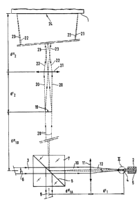
Fig. 1 illustrates diagrammatically in a plan view
along the plane of a display screen 1 a device for injecting
the light energy of a laser beam into a fibre-optic optical
waveguide. The display screen 1 recognisable by its lateral
edge serves for observling the adjustment of a fibre-optic
optical waveguide 2 which has trained on it the light of a
laser beam 3 of a laser not illustrated in the drawing.
When a compar<~tively high output is required,
there is a risk that, as a result of its high energy, t:he
laser beam 3 will damage the fibre-optic optical waveguide 2
if the adjustment is incorrect. The illuminated end 4 of
the optical waveguide 2 is therefore clamped in a precise
holding means 5, illustrated diagrammatically in the
drawing, which is displaceable in three axial directions.
When the laser outputs i.s low, the device allows energy
losses resulting from unskilled adjustment to be avoided.
One of the three axial
-3-
directions extends in the longitudinal direction of the illuminated end 4 of
the fibre-optic
optical waveguide 2, whilst the two other axial directions defane a plane
extending at right
angles thereto. The actuation of the holding means 5 is effected using several
adjusting
screws, which are also not illustrated in the drawing.
To adjust the multimode fibre-optic coupling device shown in Fig. 1, a beam
splitter 7 is
introduced into the path of the laser beam 3, the diameter of which is
illustrated by the
arrows 6, after the laser light output has been reduced in the manner
illustrated in Fig. 1.
The beam splitter 7 is a beam splitter cube, the reflecting face 8 of which
runs at an angle
of preferably 45 degrees to the propagation direction of the laser beam 3. The
reflecting
face 8 extends, like the surface of the display screen 1, at right angles to
the plane of
drawing of Fig. 1. After the holding means has been adjusted, the beam
splitter is removed
from the ray path again in order to avoid loss of output as a result of
extraction.
When the beam sputter 7, which is required only during the adjusting
operation, is located
in the ray path of the laser beam 3, a part of the laser beam 3 is extracted
as a pencil of
dissipated rays 9. After passing through the beam splitter 7, which is in the
form of a
beam splitter cube, the pencil of laser rays 10 of somewhat reduced intensity
passes by
way of a diagrammatically illustrated focusing lens arrangement 11 as a
focused pencil of
laser rays 12 to the illuminated end 4 of the fibre-optic optical waveguide 2.
The focusing
lens arrangement 11 consists preferably of a precision-optimized achromatic
lens spaced
at a distance d" 1 A from the middle of the beam splitter 7 and at a distance
d' 1 from the
end face 13 of the fibre-optic optical waveguide 2, which can be seen more
clearly in
Fig. 2 than Fig. 1; Fig. 2 ilustrates the circled portion of Fig. 1 around the
illuminated end
4 of the optical waveguide 2, in a view enlarged about twenty tithes.
As is apparent in Fig. 2, the focused pencil of laser rays 12 converges at a
convergence
angle 2a to a narrowest point 14 in the form of a constriction, and thereafter
widens as an
expanded pencil of laser rays 15 which extends as far as the end face 13,
extending at right
angles to the longitudinal axis of the fibre, of the illuminated end 4 of the
fibre- optic
optical waveguide 2, the fibre diameter of which is illustrated by an arrow
16.
The light spot 17 formed by the expanded pencil of laser rays 15 on the end
face 13 has a
diameter, illustrated by an arrow 18, which is smaller than the diameter of
the end face 13
of the optical waveguide 2.
20~~~~~
-4-
So that the energy fed in in the pencil of laser rays 15 is not concentrated
too much, the
end face 13 is spaced from the narrowest point 14 by a distance L which is
selected so that
the diameter of the light spot 17 is larger than the diameter of the pencil of
laser rays 12 at
the narrowest point 14, but smaller than the diameter of the fibre. The
distance L can be
selected, for example, so that the diameter of the light spot 17 is about half
the diameter of
the end face 13 of the optical waveguide 2, so that adjustability is good and
the edge of the
light spot 17 has sufficient safe clearance from the edge of the core of the
optical
waveguide 2. During the adjusting operation, using the holding means 5 the end
4 of the
optical waveguide 2 which can be seen in Figs. 1 and 2 is displaced in an
axial direction
and in a plane extending transversely thereto.
A part of the light fed by the pencil of laser rays 15 into the multimode
fibre-optic optical
waveguide 2 is reflected at the remote end, not illustrated in the drawing, of
the optical
waveguide 2 and passes from the inside of the optical waveguide 2 to the end
face 13 so
that this is completely illuminated from the rear side. The light reflected in
this manner
and used to illuminate the end face 13 corresponds to approximately 4 % of the
light fed
in.
When correctly adjusted, the focusing lens arrangement 11 generates at an
intended
location in the ray path a sharp intermediate image 19 of the end face 13
illuminated from
the rear side. For this purpose, the light coming from the end face 13 is
guided through
the focusing lens arrangement 11 as far as the reflecting face 8 of the beam
splitter 7 and
from there is deflected at right angles towards the display screen 1. The
associated ray
path is illustrated in Fig. 1 by a pair of rays 2Q and, because of the large
distance d" 1B
between the beam sputter 7 and the location of the intermediate image 19, is
illustrated by
interrupted lines. Depending on the positioning of the holding means S, the
location of the
intermediate image 19 is displaced laterally or along the joining line between
the beam
splitter 7 and the display screen 1.
The intended distance between the intermediate image 19 and the beam splitter
7 is
reached when the end face 13 of the optical waveguide 2 is pulled away from
the
narrowest point 14 by the distance L by the focusing lens arrangement 11. When
the end
face draws nearer to the narrowest point, the location of the intermediate
image 19 is
displaced, the light spot 17 becoming smaller and more intense. When the end
face moves
further away, the light spot 17 becomes larger and the intermediate image 19
of the end
face 13, which also contains an intermediate image of the light spot 17, draws
nearer to
~O~~J
-5-
the beam splitter 7 and thus distances itself from the display screen 1.
Between the intended location of the intermediate image 19 and the display
screen 1, at a
distance d'2 from the intended location of the intermediate image 19 and at a
distance d"2
from the display screen 1, there is a reproducing lens arrangement 21,
illustrated
diagrammatically in Fig. 1.
In the manner illustrated by the ray pairs 22 and 23 using interrupted lines,
the
reproducing lens arrangement 21 produces on the display screen 1 a
reproduction 24 of
the intermediate image 19 and thus of the light spot 17 and the end face 13
illuminated
from the rear side. The reproduction 24 only contains a sharp image of the end
face 13,
however, when the intended distance L of the end face 13 from the narrowest
point 14 of
the laser beam 3, 10, 12, 15 has the intended value. In this manner it is
possible, with fixed
positions of the display screen 1, the reproducing lens arrangement 21 and the
focusing
lens arrangement 11, to monitor and adjust the positioning of the optical
waveguide 2 after
insertion of the beam splitter 7 and reduction of the laser beam output, with
both an axial
and a radial, accurately controllable adjustment being possible.
When the intended distance I, is not accurately adhered to, the first partial
image of the
reproduction 24, namely the image of the end face 13, is blurred and the image
of the
light spot 17, recognisable on the display screen 1 as the second partial
image, is too large
or too small. When the end face 13 is sharply reproduced on the display screen
1, with
correct adjustment the image of the light spot 17, which has a smaller
diameter than that
of the image of the end face 13, is positioned concentrically in the image of
the end face
13. Where the adjustment is radially incorrect, the image of the light spot is
displaced
off axis.
The described arrangement thus allows in a simple manner a rapid and accurate
adjustment along the three spatial axes, so that damage to the optical
waveguide 2 as a
result of incorrect adjustments when operating with high laser light outputs
can be reliably
excluded.
It is also possible to use the above-described arrangement for laser beams 3
in the UV- or
IR-range instead of the visible range if the display screen 1 is sensitive to
ultraviolet or
infrared light. For example, a CCD-chip may replace the display screen 1.
202694
-6-
The adjustment of the entire system is found by a simple calculation, so that
the position
of the focus point comes to lie at the desired location.