Note: Descriptions are shown in the official language in which they were submitted.
- 2026729
D E S C R I P T I O N
Title
OIL SEPARATOR FOR
REFRIGERATION SYSTEMS
Background of the Invention
The present invention relates generally to the art
of compressing a gas. More particularly, the present invention
relates to the compression of a refrigerant gas into which a
liquid is injected during the compression process.
With still more particularity, this invention
relates to the requirement to separate entrained injected oil
from the oil-gas mixture discharged from a screw compressor in
a refrigeration system.
Compressors are used in refrigeration systems to
raise the pressure of a refrigerant gas from a suction to a
discharge pressure thereby permitting the refrigerant to be
used within the circuit to cool a desired medium. Many types
of compressors, including rotary screw compressors, are
employed to compress the refrigerant gas in a refrigeration
system.
In a screw compressor two complimentary rotors are
located in a housing having a low pressure end, which defines a
suction port, and a high pressure end, which defines a
discharge port. Refrigerant gas at suction pressure enters the
low pressure end of the compressor housing and is there
enveloped in a pocket formed between the counter-rotating screw
rotors.
2026~29
The volume of the gas pocket decreases and the
pocket is circumferentially displaced as the compressor rotors
rotate and mesh. The gas within such a pocket is compressed
and heated by virtue of the decreasing volume in which it is
contained prior to the pocket's opening to the discharge port.
The pocket, as it continues to decrease in volume, eventually
opens to the discharge port in the high pressure end of the
compressor housing and the compressed gas is discharged from
the compressor.
Screw compressors used in refrigeration
applications will, in the large majority of instances, include
an oil injection feature. Oil is injected, in relatively large
quantity, into the working chamber of a screw compressor (and
therefore into the refrigerant gas being compressed therein)
for several reasons. First, the injected oil accs to cool the
refrigerant gas undergoing compression. As a result, the
compressor rotors are likewise cooled allowing for tighter
tolerances between the rotors.
Second, the oil acts as a lubricant. One of the
two rotors in the screw compressor is typically driven by an
external source, such as an electric motor, with the other
rotor being driven by virtue of its meshing relationship with
the externally driven rotor. The injected oil prevents
excessive wear between the driving and driven rotors. The oil
is additionally delivered to various bearing surfaces within
the compressor for lubrication purposes.
Finally, oil injected into the working chamber of a
screw compressor acts as a sealant between the meshing rotors
and between the rotors and the working chamber in which they
are housed for the reason that there are no discrete seals in a
202~2~
-- 3 --
screw compressor between the individual rotors or between the
rotors and the rotor housing. Absent the injection of oil,
significant leakage paths would exist internal of the compressor
which would be detrimental to compressor efficiency. Oil
delivery and injection therefore both increases the efficiency
and prolongs the life of a screw compressor.
Oil making its way into the working chamber of a screw
compressor is, for the most part, atomized and becomes entrained
in the refrigerant undergoing compression. Such oil, to a great
extent, must be removed from the oil-rich mixture discharged from
the compressor in order to make the oil available for reinjection
into the compressor for the purposes enumerated above. Further,
removal of excess oil from the compressed refrigerant gas must
be accomplished to ensure that the performance of the refrigerant
gas is not unduly affected within the refrigeration system by the
carrying of an excess amount of oil into and through system heat
exchangers.
The need therefore continues to exist for reliable and
efficient oil separation apparatus for screw compressor
refrigeration systems which removes a predetermined and required
amount of oil from the oil-refrigerant gas mixture discharged by
the compressor.
Summary of the Invention
It will be appreciated that it is an object of this
invention to separate an entrained liquid, such as oil, from a
liquid-refrigerant gas mixture.
Finally, it is an object of the present invention to
_ 4 - 2~26~29
provide easily fabricated and relatively inexpensive apparatus
for efficiently separating and recovering entrained oil from the
mixture discharged by a rotary screw compressor in a
refrigeration system.
An appreciation of these and other objects of the
present inventions will be gained when the following material is
taken in consideration together with the attached drawing
figures.
According to this invention, there is provided a
refrigeration system comprising: an oil-injected screw
compressor; a condenser; an oil separator disposed in said system
in flow communication with each of said compressor and said
condenser, said oil separator receiving a mixture of compressed
refrigerant gas and entrained oil from said compressor and
internally splitting said mixture for further delivery to two
discrete locations within said separator where separate
centrifugal oil separation processes occur, said oil separator
defining a common sump for the oil separated at said discrete
locations; an evaporator; and a metering device, said compressor,
said condenser, said oil separator, said evaporator and said
metering device being connected for refrigerant flow.
According to another aspect of this invention there is
provided an oil separator for use in a refrigeration system
employing a compressor comprising: a generally U-shaped housing
having first and second generally upstanding leg portions
connected by a common sump portion; means for splitting the flow
of a mixture of refrigerant gas and entrained oil received from
said compressor, said flow splitting means communicating a
,
, ., ~
2 ~ 2 9
portion of said mixture into each of said leg portions; and means
extending into the interior of each of said leg portions for
communicating refrigerant gas, from which oil has been separated,
out of each of said leg portions.
According to a further aspect of this invention, there
is provided a method of separating oil from the mixture of
compressed refrigerant gas, in which oil is entrained, which is
discharged from a screw compressor to an oil separator in a
refrigeration system comprising the steps of: delivering said
mixture at a compressor discharge pressure to said oil separator;
splitting the flow of said mixture into relatively equal portions
prior to separating said oil therefrom; delivering each of said
split portions of said mixture to a different location internal
of said oil separator; imparting a swirling motion to each of
said portions of said mixture at each of said different locations
internal of said separator so as to centrifugally disentrain oil
from each of said portions of said mixture at each of said
different locations; collecting the oil disentrained from each
of said portions of said mixture at each of said different
locations in a common sump; and driving said disentrained oil and
said gas from which said oil has been disentrained out of said
oil separator under the impetus of compressor discharge pressure.
Preferred features of the invention will be apparent
from the following discussion. Refrigerant gas, in which oil is
entrained, is delivered from the discharge port of a compressor
to flow splitting apparatus which divides an tangentially
delivers separate, relatively equal portions of the mixture to
the interior of each of the upstanding leg portions of the U-
2~672~
- 5a -
shaped housing. The delivery of the portions of the mixture into
the legs of the U-shaped housing is therefore accomplished in a
manner which immediately induces a swirling motion into the
portions of the mixture entering the leg portions so as to cause
the disentrainment of the oil from the mixture by centrifugal
force.
The disentrained oil drains to a common base or sump
portion of the separator by force of gravity. Open ended conduit
penetrates and extends into the upper region of the tubular leg
portions of the housing to a point generally below the level of
entry of the gas-oil mixture which is delivered into the leg
portions by the flow splitting apparatus.
The open end of such penetrating conduit is disposed
generally in the axially central region of the tubular leg
portions where, because of the disentrainment and draining of the
oil which occurs along the inner side walls of the housing,
relatively oil-free gas at discharge pressure is found. That
gas, from which oil has been separated, is
'
2026729
communicated out of the leg portions, through the conduit,
under the impetus of the discharge pressure which is found
within the interior of the separator whenever the compressor is
operating. The gas passes through the open ended conduit
penetrating each leg portion and is directed to the condenser
of the refrigeration system in which the oil separator is
employed.
The common sump portion of the separator, to which
separated oil drains and in which the separated oil collects,
is in flow communication with various locations within the
compressor. The discharge pressure in the interior of the
separator, which exists whenever the compressor is in
operation, is employed to drive separated oil from the sump
back to the compressor for re-use in the manner suggested above
in the Background of the Invention.
The oil separator of the present invention provides
for many advantages, some of which are readily apparent and
others of which are somewhat surprising. Among the
recognizable advantages of the oil separator of the present
design are the reduced fabrication costs associated with it.
This is particularly true with respect to the tubing which
penetrates the legs of the separator. That tubing is tubing
which already exists, in one form or another, as the conduit
which connects the compressor to the condenser in a
refrigeration system for the conveyance of compressed
refrigerant gas therebetween. One not so obvious advantage to
the oil separator of the present invention is that it does not
fall within the definition of an ASME pressure vessel and is
not, therefore, subject, because of its diameter, to various
ASME requirements relating to pressure vessels.
2026729
Still another advantage of the present invention is
the elimination of the need for a discrete oil sump within the
compressor as well as the need for a compressor oil sump
heater. Further, the separator of the present invention is
conducive to use with compressors of widely varying capacities.
Finally, the oil separator of the present invention
exhibits the somewhat surprising advantage of providing for
better sound and frequency attenuation than its previous
counterparts. Specifically, the splitting of the flow of the
mixture from the compressor to the oil separator prior to the
occurrence of the separation process decreases the surface area
at the location of the occurrence of the separation process
thereby resulting in better sound attenuation characteristics.
These resulting characteristics are, in fact, similar to the
characteristics of previous installations in which a discrete
discharge line muffler is employed.
The "U"-shape of the separator housing also allows
for the "tuning" of the separator to frequency decouple it
from the compressor with which it is associated. By doing so
the development of unwanted and possibly destructive
frequencies within the separator resulting from frequencies
associated with the operation of the compressor is prevented.
The "U"-shape of the housing allows the oil separator of the
present invention to be "tunedn to eliminate unwanted
frequencies simply by adjusting the heights of its leg portions
which has a negligible effect on the oil separation process.
Description of the Drawing Figures
Figure 1 schematically illustrates a refrigeration
system according to the present invention.
2026729
Figure 2 illustrates the relationship of the oil
separator of the present invention with the condenser of the
refrigeration system of Figure 1.
Figure 3 is a perspective view of the oil separator
of the present invention.
Figure 4 is a top view of the oil separator of the
present invention.
Figure 5 is a cross sectional view of the oil
separator of the present invention taken along line 5-5 of
Figure 3
Figure 6 is likewise a cross sectional view of the
oil separator of the present invention taken along line 6-6 of
Figure 3.
Description of the Preferred Embodiment
Referring initially to Figures 1 and 2,
refrigeration system 100 includes an air-cooled condenser 102
from which condensed refrigerant gas is delivered, after
passing through a metering device 104, to an evaporator 106.
Vaporized refrigerant gas is delivered from evaporator 106 to
compressor 108 which is preferably a screw compressor.
Condenser 102 is air-cooled and is preferably of
the split type having separate heat exchange sections 102a and
102b. Fan 110 is disposed between condenser sections 102a and
102b so as to draw air through each of them in a heat exchange
rela~ionship with the compressed refrigerant gas which passes
therethrough upon delivery of the gas to the condenser from oil
separator 10.
2026729
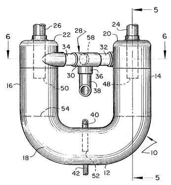
Referring additionally now to Figure 3, oil
separator 10 is generally comprised of a tubular U-shaped
housing 12 having first and second upstanding leg portions 14
and 16 respectively. The length of leg portions 14 and 16 is
predetermined so as to de-tune separator 10 with respect to
frequencies associated with the operation of the compressor
from which it receives the mixture of oil and compressed
refrigerant gas. This prevents, in a relatively simple and
expeditious way, the development of unwanted and possibly
destructive frequencies within the refrigeration system.
The likewise tubular portion of housing 12 which
connects leg portions 14 and 16 defines a common oil sump 18 in
its lower portion. It will be appreciated that housing 12 will
preferably be a unitary structure fabricated from a single
length of cylindrical tubing bent into a horse collar-like
shape. The upper ends of leg portions 14 and 16 are closed by
caps 20 and 22 which define apertures through which conduits 24
and 26 penetrate and extend into the interior central region of
each of leg portions 14 and 16 of housing 12.
Also connecting between leg portions 14 and 16 is
flow splitting apparatus 28 which internally divides the flow
of the mixture of compressed refrigerant gas and oil received
by separator 10 into relatively equal portions, as will be more
fully described hereafter, for delivery to the leg portions of
housing 12. Flow splitting apparatus 28 is comprised generally
of a T-section 30 and conduits 32 and 34. T-section 30 has an
entrance portion which is connected to conduit 38 through which
the mixture of compressed refrigerant gas and entrained oil
discharged from the compressor is directed into oil separator
10.
2026729
Sump 18 is penetrated by conduit 40 through which
oil, which has been separated from the mixture of compressed
refrigerant gas and oil discharged from the compressor, is
directed out of separator 10 for re-use within the compressor.
A drain connection 42, with shutoff valve, may be provided at
the lowermost portion of sump 18 through which sediment or
contaminated oil can be drained or oil samples taken.
Referring now to all of the drawing figures, it
will be appreciated that flow splitting apparatus 28 is angled
with respect to a plane passing through the center lines of
tubular leg portions 14 and 16 of U-shaped housing 12. As a
result, openings 44 and 46, through which the split flow of
compressed refrigerant gas and oil enters leg portions 14 and
16 of the separator respectively, open in a tangential manner
into the side walls of the leg portions.
That is, the portions of the split flow of
compressed refrigerant gas and entrained oil passing out of
conduit portions 32 and 34 of flow splitting means 28 are
directed along the inner side walls of leg portions 14 and 16,
generally tangent to the cylindrical volume defined by the leg
portions, upon entry thereinto. As a result, the mixture of
compressed refrigerant gas and entrained oil entering leg
portions 14 and 16 is immediately imparted a swirling motion
and follows a generally spiroidal path around and down the
inside walls of the leg portions.
It will be noted that openings 44 and 46 in leg
portions 14 and 16 are preferably at an elevation higher than
the open-ended bottom faces 48 and 50 of penetrating conduits
24 and 26. Therefore, open-ended bottom faces 48 and 50 of
'0 conduits 24 and 26 are shielded from the oil-laden compressed
refrigerant gas as it enters the respective leg portions.
2026729
11
It will also be noted that conduit 40 has an open
end 52 disposed in the lower portion of oil sump 18 at a
location below the n~ inAl level 54 of oil which resides in the
sump and that although, as illustrated, dlscharge conduit 38
rises up into entrance portion 36 of T-section 30, discharge
conduit 38 and entrance portion 36 of flow splitting means 28
could optionally lie in a common horizontal plane. Finally, a
baffle-like element 58 can be provided which assists in
portioning the flow of refrigerant gas and oil internal of the
flow splitting apparatus and which acts to direct the resultant
streams of gas and entrained oil into connector conduits 32 and
34.
OPERATION
As mentioned above, flow splitting means 28 is
angled with respect to a plane passing through the axes of the
preferably cylindrical leg portions 14 and 16 so that
relatively equal amounts of the refrigerant gas and entrained
oil (represented by arrows 56 in the drawing figures) exiting
connector conduits 32 and 34 enters leg portions 14 and 16
tangentially through openings 44 and 46 along the inner side
walls of the leg portions. The mixture entering the leg
portions swirls around and follows a spiroidal path along the
inner side walls 60 and 62 of the leg portions as it is
generally drawn downward toward common sump 18 by force of
gravity.
2026729
12
As will be appreciated, since the entrained oil
within the mixture received through openings 44 and 46 is
heavier than the compressed refrigerant gas in which it is
entrained, the centrifugal force created by the swirling spiral
flow of the mixture within the leg portion will cause the
entrained oil to migrate radially outwardly within leg portions
14 and 16 and to impact, adhere and slide downwardly along
inner walls 60 and 62. The separated oil then collects in sump
18.
It will also be appreciated that by providing for
oil separation at two discrete locations within the separator,
each of which communicates with a common sump, that should any
clogging or other malfunction occur related to one separation
area, the second area will continue to function thereby
providing increased reliability with respect to the
availability of oil for use in the compressor. Further, by
splitting the flow a lesser volume of mixture is acted upon in
each instance. As a result, the separation process for each
portion of the mixture is more efficient as compared to a
separation scheme in which the entire volume of the mixture
discharged from the compressor is acted upon in one location or
process and better sound attenuation is achieved. The need for
discrete sound attenuation apparatus, such as a discharge line
muffler, is thus eliminated.
The generally axially central region of the
interior of tubular leg portions 14 and 16 will contain
refrigerant gas from which oil has been disentrained as a
result of the oil separation which occurs along the inner walls
of the leg portions. Such gas is forced into open ends 48 and
~0 50 of conduits 24 and 26 and which are above the nominal level
- 2026729
13
of 54 in sump 18 by the continued entry of additional discharge
gas (in which oil is entrained) into the upper region of the
leg portions through openings 44 and 46. Continued entry of
the oil-laden gas into the separator and the forcing of gas
from which oil has been separated out of the leg portions
through conduits 24 and 26 will continue to occur so long as
compressor 108 is operating by virtue of the lower downstream
pressure found in the refrigeration system.
The oil in sump 18 is likewise forced, by the
discharge pressure which exists in the interior of the
separator whenever the compressor is operating, through the
open end 52 of oil supply conduit 40 to various compressor
locations which require cooling, sealing and lubrication. Such
locations, by design, are exposed, vent to or open into areas
within the compressor which are at less than compressor
discharge pressure so that both oil and refrigerant gas are
driven from separator 10 and are delivered to locations at
which they are next employed by differential pressure and
without the need for mechanical assistance or moving parts.
Optionally an oil pump (not shown) might be employed to move
oil from sump 18 back to compressor 108.
While the refrigeration system oil separator of the
present invention has been disclosed in a preferred embodiment,
it will be appreciated that various modifications thereto might
be made which are within the scope of the invention represented
by it. Therefore, the scope of the present invention is to be
limited only by the language of the claims which follow.
We claim: