Note: Descriptions are shown in the official language in which they were submitted.
` 2~2~927
.~
Elui~lz~d-bed Combustion Furnace
Field of ~he Invention
The present invention relates to a fluidized-bed
inaineration system, comprising a fluidized-bed furnace
and a control apparatus for use in disposal of waste
.
materials, such as municipal wastes.
Back~round Art
A fluidized-bed incineration furnace is an apparatus
for disposal of substantially combustible waste
materials, whose furnace bed is made o partlculate
materials, such as sand particles. These particles can
be held in suspension (i.e. fluidized) by a blast of air
blown through a series of holes in the blow pipes laid
parallel to the bed-bottom. The waste materials undergo
drying, thermal decomposition and combustion in the
gaseous ~txeam. This phase of combustion in ~luidized-
bsd furnace i8 called first-stage combustion. The
combustible gas~s ~nerated in the irst-stage combustion
are urther burned with the addition of supplementary
air. This phase is called second-stage combustion. The
flue gas, a mixture o the products of aombustion from
the two-stage combustion proce~s, i~ passed through a
heat exahanger, through a dust aolleator, a stack and is
ultimately discharged into the atmosphers.
On occasion, a suddsn changs in ths normal
combustion condition may occur when a largs volume or
high calorifia wastes are introduced into the furnace.
.
2~2~27
This situation oauses a sudden generation of excess flue
gases, leading to a temporary unbalance between the flue
gas and the supplementary air normally required for
complete combustion. Such lncomplete combustion of flue
gases in the second-stage combustlon results in releasing
harmful unreacted flue gases and particulate materials
into the atmosphere, causing possible environmental
pollution.
To prevent such events, it is a general practice at
present to monitor oxygen concentration in the flue gas
line to guide in determining the amount of supplementary
air required for complete combustion.
However, the traditional control techniques are
based on the eedback signals from the sensors located
distantly from the site o combustlon, causlng a time
delay in actlvating the supplementary alr supply. It is
clear that a corrective action should be timed closely
with the occurrence of sudden imbalance in the furnace
load. Another problem which causes a delayed action is
the response tlme oE the instrument for the analysi~ of
oxygen concentratlon, whioh must be completed before
appropriate signals can be transmitted to the actuator to
increase the flow of supplementary air to the second-
staga combustion region. For these reasons, the present
art of 1uidized-bed control is insuficient to regulate
the emissions of harmul gaseous and particulate matters
generated by a ~udden imbalance in the furnace load,
caused by an introduction of a large quantity or size of
furnace charge.
.~ . . . ~ .. ~ . . .
3 20~927
Summary of the Invention
Therefore, it is an ob~ect of the present invention -~
to provide a system of non-polluting operatlon of a
fluidized-bed furnace wherein an efficient combustion
process is promoted by closely coordinating the first-
and second-stage combustion processes.
Said ob~ectlve is attalned by direct monitoring of
the combustion condltions of the furnace and by
correctlng the response-time delay to changes in the
oxygen concentration in the flue gas stream.
It is yet another obJect of the present invention to
supply supplementary air quiakly, in response to dynamia
demand requirements of the fluidized furnace, to correct
an imbalance in the combustlon process by the timely
detection of combustion conditions.
It is still another ob~ect of the present invention
to provide a system to guickly and accurately regulate
the supply of supplementary air, ln response to the
information supplied by direct monitoring of the
aombu~tion o the fluidized furnaae.
It was found after various analysi~ of process data
that the above ob~eativeY are realized by direat
moni~oring of the physiaal parameters associated with the
combustion processes within the furnace, for example,
measurements of the radiative energy or furnace pressure.
In other words, one aspect of this invention
concerns a system of efficient control of the combustion
2~2~92~
of the fluidlzed~bed furnace whereln the combustion
process comprises: .
(a) the first-stage combustion of furnace charges .
taking place in a bed of fluid-like environment, created
by the action of a mixture of the primary air blowing
through a series of pipes located at the bottom of said
furnace; and
(b) the products of combustion generated from the
first- tage combustlon are mixed w1th supplementary air
to further treat the flue gas in the second-stage
combustion process; wherein
(c) a feedback control of the volume of sald
supplementary air is achieved accordlng to the
lnformation generated ~rom the combustion process
parameters within the furnace.
It is still another aspect of this invention to
furnish a fluidized-bed lncineration furnace with the
: control system mentioned above, including monitoring of
the process parameters o~ combustlon with the use of
sensors loaated on the furnace itself to direatly monitor
said parameters suah as, radiative energy or furnace
pre~sures, so that quiak and aaaurate response can be
made to the volume requirements of the supplementary air
in the second-stage aombustion.
It i9, thereore, ~he aonoluding aspect of this
invention that an efficient utilization of the overall
systen, as desaribed above, enables substantially
pollution-free operation of the fluidized-bed furnace to
be carried out even if the $urnace loading is suddenly
', '' ' " . ,' ' ' , ' ;' ; ` ' ' "' " ' ', '' '' ' "' ,' . ` ` ''
2~2~927
altered because o~ an introduction of a large volume or
high calorific value charges, and the consequent
temporary generat$on of a large guantity of excess flue
gas.
BR~EF DESCRIPTION OF THE DRAWINGS
Figures 1 to 3 show varlous aspecks of the preferred
embodiments of this inventionO Figure 1 is a schematic
representation of the overall arrangement of the invented
fluldized-bed incineration system. Figure 2 i9 a
implified representation of the control apparatus.
Figure 3 is a graph showing the tlme-dependent variations
o the values o radiation pyrometer and of the oxygèn
concentratlon monltor.
Figure 4 ls a schematic representation of the
furnace system and its control apparatus. Figure 5 shows
the block diagram of the control methodology. Figure 6
shows the block diagram o the aonkrol logia.
~ ' ..
- 2~26~27
DET~ILED D~CRIPTION OF THE PREFERRED EMBODI~ENTS
The preferred embodiments of the present invention
are explained with reference to the figures presented.
Fluidized-bed System
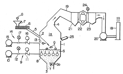
Figure 1 is an overall schematic representation of a
fluidized-bed inc~neration system that will enable
substantially pollution-free operation of a waste
disposal system.
In Figure 1, a furnace 1 contains floatable bed
medium S, such as sand, in the interior la of the furnace
1. This medium S ls maintained at elevated temperatures
during the normal operation by the heat of combustion of
the furnace charge G.
The furnace 1 is equipped with a loading port 2,
through which the charge G ls lntroduced onto the
1uidized bed medium S; a discharge port 3, through whloh
non-combustible re~idue materials Go are discharged, and
an exhaust opening 4 through which the gaseous products
of combustion a~n be vented.
The loading port 2 i9 equipped with a shoot 5 to
which iR attached a loading apparatus compriRed of a
~arew conveyor 6 and a hopper 7 to direct the incoming
charge G onto the aonveyor 6. The charge G is
transported further by the conveyor 6 into the interior
la of the furnace 1 through the shoot 5, and which charge
G is ultimately led onto the surface of the fluidized bed
.
-: 2~2~927
At the bottom of the furnace interior la, are
present several (five in this preferred embodiment)
parallel blow pipes 8 which are almost completely covered
by the bed medium S. When gaseous fuel i~ blown into the
pipes, through the air supply device 9, and discharged
into the furnace interlor la through the blow holes in
the pipes, the particles of the bed medium become
su~pended, i.e, fluidized, to form a fluidized-bed, in
the gas stream.: Tha gas stream produces an effect of
suspending the charge G ~n the bed medium S. The action
of the burning fuel gas results in the drying, heat
decomposition and combustion of the charged material G.
This process i~ termed first-stage combustion and the air
required for this operation i8 termed first-stage
combuqtion air (hereinafter, simply as FS-air).
..
Combustion Processes and Air Supply Requirements
The FS-air supply device 9 comprises a FS-air supply
fan 10, a damper 11 associated thereof to ad~ust the air
~low, a signal generator 12 to indiaate the FS-air 10w
volume into the furnace interior la. The volume of air
supplied by FS-air supply device 9 is affected by several
Paator~ including the base value of the air volume
required to areate a gas aolumn to suspend the bed
medium, the guality of the bed media (in the present
invention, sand quality), and the temperature of the
fluid bed S.
Ths furnace 1 is also equlpped with an opening 13
for the lntroduction of the second-stage combustion air
~ . . , , .. .. " , . , ., . ~. . - . ..... . . ..
8 ~ 2 7
, ....
(hereafter simply as SS-air), from a SS-alr supply device
l4, into the interior of the furnace la at a location
above the fluidized bed 5 so as to react with the gaseous
products of cc~bustion gsnerated in the irst-stage
combustion process.
The SS-air supply device 14 comprises, simllar to
FS-alr supply device 9, a SS-air ~upply fan 15, a damper
16 to regulate the air flow and a flow meter 17 to ;
indicate the SS-alr low volume into the furnace interior
la.
It should be noted that although there i8 only one
SS-air supply device shown in Figure l, in actual
practice, there oan be present a plurality of
independently controllable units around the periphery of
the furnace to provide optimum combustion efficiency.
Removal of Flue Gases
The exhaust opening 4 is attached to an exhaust
removal llne l9, equipped with an exhaust fan 20, which
transports the gaseou~ products of combustion, rom the
~urnace interior la to the entranae to the chimney 18, to
be vented to the atmosphere. In between said openin~ 4
and the chimney 18, said line l9 i9 further equipped
with, beginnlng with a du~t isett1ing facility 21, a heat
recovery boiler 22 and an electrostatic dust precipitator
23.
Air Supply Control Device
. :, ,. ,. . .............. ~ . , , ..... . ., . ~.. ..... . ......... .. ..
" "
9 2~2~27
The control of the supplementary alr supply is
carried out according to the informatlon obtained from a
feedback arrangement. Shown ln Figure 2 are two basic
elements of such a feedback arrangement utilized in the
preferred embodiments.
In an example of the preferred embodiments, an
oxygen concentration analyzer 24 (hereinafter termed an
oxygen meter), located at the entrance to the electric
pr~cipitator 23, and a radia~ion pyrome~er 25, located on
the furnace 1, are connected to a second-stage combustion
control apparatus 26 to provide a information feedback
arrangemen-t, between the oxygen meter 24 and the
radiation pyrometer 25, so a~ to enabl~ said apparatus 26
to ad~ust the supply of SS-alr to respond approprlately
to the demands o the changing furnace load.
The operation of the second-stage combustion control
apparatus 26 is explained with reference to Figure 2;
1. a total-air-requirement computing device 27
(herelna~ter referred to a~ computing device 27)
calculates an initial operational value oE the total air-
volume requlrem2nt, based on ~he sum o~ the value~ Eor
both FS-air supply device 9 and SS-air ~upply device 14;
~ . a SS-air computing device 28 receives both said
value ~or the total air 10w reguirement and the inltial
FS-air Elow value rom a FS-air 10w meter 12, and
calculates a difference between said total air flow value
and the current value oE the FS-air flow.
3~ a SS-air flow controller 29 is g$ven said
difference (to be the current air requirement for the
lo ~2~%7
second-stage combustion process) and operates the SS-air
supply devlce 14 to maintain tha SS-air flow, with feed :;
back signal *rom the SS-air flow meter 17. ;~
In addition to the above basic operation of the
furnace system:
4. said SS-air flow controller 29 responds to
varying demands for oxygen in the system a3 dictated by
the signal from an adding computer 32,
4.1. which computer 32 receive~ signals from the
oxygen concentration controller 30, and compares the ^ -
preset value with the signal from oxygen meter 24,
located at the entrance to the electric preaipitator 23,
as necessary; additionally,
4.2~ which aomputer 32 receives signals from said
SS-air computing deviae 28 and from oxygen controller 30
to aativate the SS-air supply device 14 to provide the
required amount of oxygen (as contained in air) to the
furnace system to satisfy the new combustion condition.
The oxygen concentration in the flue gas is a good
indiaator of tho state o combustion in the system
because a low oxygen reading indiaates incomple~e
aombustion whlle a high oxygen reading indiaates excess
SS-air supply; and therefore, by following the procedure
desaribed in the above preferred embodiment, it i~
possible ~o operate the urnaae system at it optimum
effiaiency.
In addition to the advanced operational mode of the
furnace described so far, the feedback arrangement, by
means of SS-alr flow correating computer 31 acting on the
2 7
signals from the radiatlon pyrometer 25, operates as
follows:
5. said SS-air flow controller 29 responds to a
signal from said SS-air computlng device 28, which
receives signals from:
5.l the SS air flow correcting computer 31, which
calculates the current air flow requirement based on the
current input of said radiation pyrometer 25, and
5.2 the oxygen concentration controller 30, and
5.3 the SS-air computing device 28,
to calculate a new signal, based on the input from all of
the foregoing, and forwarded it prefersntially to the SS-
air flow controller 29 to activate the SS-alr supply
device 14 to meet the new (or unchanging) need o$ the
second-stage combustion process.
Although not shown in the figures, when it ls
neces~ary to supply SS-air from a plurality of secondary
air supply open1ngs, the SS-air supply device 14 can be
ad~usted to apportlon the alr to diferent openings. It
is, urthermore, pos~ible to aontrol the air low to said
diferen~ openln~ automatically, by elec~riaally
aonneating the SS-air supply devlce 14 directly to SS-air
flow correcting computer 31.
The fluidized-bed inaineration ~ystem and the method
for ~he aontrol thereo, a~ described in the preerred
embodiments above, are able to minimize the generation of
pollution-caus1ng gaseous products of combustion
resulting from the process of incomplete combustion
aaused by sudden fluctuations in the furnace loading.
^ 12 2~
:, .
Such fluctuations are detected as a sudden rise in the
furnace temperature by the radiation pyrometer 25, whose
signals are processed by the second-stage combustion
control ap~aratus 26 which quickly ad~ust SS-air supply
device 14 to increase the alr supply to second-stage
combustion process.
Feedback Control Systems
The radiation pyrometer 25 converts the radiative
energy of combustion into temperature, whlch responds
quickly to changes in the radiative energy within the
furnaaa. Figure 3 shows time-dependent variations within
the furnaae environment as detected by the radiation
pyrometer 25 and by the oxygen meter 24, respectively.
It can be seen in Figure 3 that incomplete combustion is
deteoted first by the radlation pyrometer 25 (as a rise
ln the furnace temperature), and a short time later (15
scconds), by the oxygen meter 24. This example
demonstrates that it would be possible to prevent
inaomplete aombu~tion substantially b~ ad~usting the
supply of SS-air quiakly to respond to the generation of
excess flue gas.
Next, the use o pressure as an indicator of the
state of combustion within the furnace is described.
Figure 4 18 a schematic diagram of the furnace and
its control system used in a preferred embodiment of this
invention.
The numberiny scheme and the function of the various
elements shown in Figure 4 are identical to those shown
~3
2~2~927
in Figure 1, and their explanation~ will not be repea-ted
here. The prinaipal difference in the concepts descrihed
by these figures is the replacement of the radiatlve
energy with the furnace pressure a~ a controlling
indicator of the state of combustion within the furnace.
In contrast to the previous example, this example of
the preferred embodiments utilizes a pressure sensor 125,
located on the furnace 1, to regulate the flow volume of
SS-air by the second-stage combustion control apparatus
26 in conJunction with the oxygen meter 24.
The operation of the second~~tage combustion control
apparatus 26 is explained ln reference to Fiyure 5, in a
simplified version of the detailed explanation ofered
earlier or the aase o~ radiation pyrometer 25.
As before, the computlng device 27 first determines
an initial operational value of the total air volume
requirement, to supply both FS-air supply device 9 and
the SS~air supply device 14. The SS-air computing
deviae 28 aalaulate~ the SS-air volume requirsment as the
difference. between the initial total air volume
re~uire.ment and the curren~ air volume obtained rom the
FS air flow meter 12. The SS-air flow aontroller 29 ;
operates the SS-air supply device 14 so as to maintain
the SS-air ~low at the demanded value with a eedbaak
signal from SS-air 10w meter 17 .
Furthermore, the status of the oxygen aonaentration
in the flue gas i~ monitored with the oxygen meter 24,
located at the entrance pathway 19 to the eleatria
preaipitator 23. The measured value. of the oxygen
2 7
concentration is entered into sald oxygen concentration
controller 30, and further combined ln the adding
computer 32 with the signal from SS-air computing device
2~. The combined slgnal i8 used as a reference signal
for the SS-air air flow controller 29, which controls the
oparation of the SS-air supply device 14.
The pressure signal from the furnace pressure sensor
125 is transmitted to a moving-average-computer 132,
processed and sent to a si~nal processing computer 33.
The signal processing computer 33 compares the averaged
value from the moving-average-computer 132 with the
current-value signal generated by pressure sensor 125,
and calculates the degree oP deviation between the two
values. The processed ~ignal i8 sen~ to the adding
aomputsr 32 to correct the reerence signal to the SS-air
flow controller 29 to aativate the SS-air supply device
14.
In praatice, when the furnaae load i~ suddenly
increased, the pressure o the interior o the furnace la
increases correspondingly as a re~ult o the generation
o~ exae~s gaseous produats o~ combustion. The high
pres~ure values are compared with the moving-average-
values, and only those values which exceed a certaln set
value are ~orwarded to the adding computer 32, which
initiates the corrective action of the SS-alr flow
controller 29.
The control signal of the SS-air flow controller 29
i~ transmitted to SS-air volume regulator 36 to activate
the damper 16 of the SS-alr supply device 14 to regulate
'; ., . . ~
, " , ~ ," ~ , ,
15 ~ 27
the air supply to the second-stage combustion process.
The siynals from the signal processing computer 33 can
2180 be transmitted to the FS-air supply device 9 to
activate the FS-air volume regulator 35 to vary the air
volume supplied to the fir~t-stage combustion region.
The pressure variation ln the interior of the
furnace la reflects closely the state of combustion -;
thereof when the FS-air flow volume is kept constant.
However, the relative relationship between the furnace
. i .
pressur~ and ~he state of combu~tion is altered when the
operating condltions are changed by, for example, the
cessation of loading. Therefore, it is one o the
feature~ of this invention that the pressure signal is
not used direatly to regulate the SS-air flow but that it
is used only as an integral parameter within the overall
control sf the second-stage combustion control apparatus
26.
Although not shown in the figures, when lt ls
necessary to supply SS-air to a plurality of secondary
air supply openings, the SS-air supply device 14 aan be
utilized to distribute the air to diferent openings. It
is, urthermore, possible to aontrol the air flow to a
particular openlng through ~ignal processing computer 33
to drive the SS-air supply apparatus.
General Summary
Ths fluidizad-bed inclnaration system and the method
for the control thereof as described in the preferred
embodiment above, are able to minimize the generation of
. ~ : ,': ., ' ' ' '. :
~ 16
2~2~27
pollution-causing gaseous products of combustion
resulting from the process of incomplete combustion. Such
1uctuations are caused by sudden changes in the
operating conditlon, for example~ a large volume or
calorifia value of furnace charge. Such an event is
detected as a sudden rise in the furnace pressure,
monitored with a furnacs pressure measuring apparatus
125, whose signals are proceRsed by the second-stage
comhustion control apparatus 26, which quickly adJust SS-
air supply devlce 14 to prevent incomplete combustion in
the second-stage combustion process.
It should be noted that although the preferred
embodlment described above utilized a radiation pyrometer
as an example of the techniques of measuring the thermal
radiation energy generated within the furnace, but other
thermal radiation measuring techniques~ such as
brlghtness meters and others, can also be adapted. Also,
other systems of f~edback control~ in con~unction with
tha radiation pyrometer and the pressure sensors can also
be used.
It is alear rom the explanation8 provided that the
present invention provides an efficient and effective
control of incomplete combustion aissooiated with the
operatlon of fluidized-bed incinerators, caused by
fluctuatlons in the furnace load, such as a temporary
overload or an introduction of unusually high calorific ~ ;
furnace charge.
~: . ` : ` ; . ! ` `: , . . . :,,. . "" . . , :; ` : . ` ,. "