Language selection

Search

Patent 2027300 Summary

Third-party information liability

Some of the information on this Web page has been provided by external sources. The Government of Canada is not responsible for the accuracy, reliability or currency of the information supplied by external sources. Users wishing to rely upon this information should consult directly with the source of the information. Content provided by external sources is not subject to official languages, privacy and accessibility requirements.

Claims and Abstract availability

Any discrepancies in the text and image of the Claims and Abstract are due to differing posting times. Text of the Claims and Abstract are posted:

  • At the time the application is open to public inspection;
  • At the time of issue of the patent (grant).
(12) Patent: (11) CA 2027300
(54) English Title: ELECTRIC CONNECTION DEVICE INTENDED TO BE PLACED IN THE WALL OF A METALLURGICAL CONTAINER IN CONTACT WITH MOLTEN METAL
(54) French Title: CONNEXION ELECTRIQUE POUR PAROI DE RECIPIENT A METAL EN FUSION
Status: Expired and beyond the Period of Reversal
Bibliographic Data
(51) International Patent Classification (IPC):
  • H01R 13/533 (2006.01)
  • C21C 05/52 (2006.01)
  • F27B 03/08 (2006.01)
  • H05B 07/06 (2006.01)
(72) Inventors :
  • HAMY, MICHEL (France)
  • MAURER, GHISLAIN (France)
  • LEBRUN, CHRISTIAN (France)
  • GROSJEAN, JEAN-CLAUDE (France)
(73) Owners :
  • INSTITUT DE RECHERCHES DE LA SIDERURGIE FRANCAISE
(71) Applicants :
  • INSTITUT DE RECHERCHES DE LA SIDERURGIE FRANCAISE (France)
(74) Agent: ROBIC AGENCE PI S.E.C./ROBIC IP AGENCY LP
(74) Associate agent:
(45) Issued: 2001-07-24
(22) Filed Date: 1990-10-10
(41) Open to Public Inspection: 1991-04-12
Examination requested: 1997-06-18
Availability of licence: N/A
Dedicated to the Public: N/A
(25) Language of filing: English

Patent Cooperation Treaty (PCT): No

(30) Application Priority Data:
Application No. Country/Territory Date
89 13 636 (France) 1989-10-11

Abstracts

English Abstract


The electric connection device comprises an electrode
(5), a sleeve (19) mounted around a projecting end part (8)
of the electrode (5), and an arrangement for cooling the
sleeve (19) with a cooling fluid comprising at least one
system (20, 20') of nozzles (21) spraying cooling fluid onto
the outer surface of the sleeve (19).


Claims

Note: Claims are shown in the official language in which they were submitted.

-7-
CLAIMS
1. Electric connection device intended to be placed in
the wall of a metallurgical container or furnace containing
a molten metal mass, said device comprising:
an elongated metal body intended to be inserted in and
extend through the wall of the container so that one of its
ends is put in contact with the molten metal and the other
end constitutes an end part projecting outside the container
and connected to a terminal of an electric supply;
a sleeve composed of a material which is a good heat
conductor mounted concentrically with the projecting end
part of the body;
and means for cooling the sleeve with a cooling fluid,
such as water;
said device being characterized in that said sleeve
cooling means comprise at least one rack of nozzles which
spray the cooling fluid onto the outer wall of the sleeve.
2. Device according to claim 1, characterized in that
the cooling fluid is mixed with a gas, such as air.

Description

Note: Descriptions are shown in the official language in which they were submitted.


G .'' ',, 4 ~. ~'y ~: S f
~3 ~d b ~ ~
_ ~ _
ELECTRIC CONNECTION DEVICE INTENDED TO
BE PLACED IN THE WALL OF A METALLURGICAL
CONTAINER IN CONTACT WITH MOLTEN METAL
The present invention relates to an electric connection
device intended to be placed in the wall of a metallurgical
container and put in contact, by one of its ends, with a
mass of molten metal contained in the container, the other
end, cooled by a fluid, extending out of the wall of the
container and being connected to a terminal of an electric
1C1 supply
A device of this type, disclosed in the document
FR-A-2,566,98, comprises a sleeve composed of a material
which is a good heat conductor, such as copper, mounted
around the prajecting and cooled end in contact with a
y5 circulating fluid. The cooling means for the sleeve
disclosed in this document are preferably constituted by at
least one groove provided in the outer lateral surface of
the sleeve, in which the cooling fluid circulates, and a
jacket closing said groove and disposed around the sleeve,
Zp said jacket being provided with fluid inlet and outlet means
which are connected to the ends of the groove and are also
connected to a cooling fluid supply.
As an alternative, the grooves may be replaced by
channels provided inside the sleeve, but this solution has
~5 the drawback of requiring a delicate machining of the
sleeve. The previously-described solution consequently
remains the preferred one according to the cited document.

1~ ,a ,~~i ,-A ~n
a
4l ~. ~' . t . ~ d : ,v
it,! $_ i YcJ 1 2.~ 4 e.l
- 2 -
Another solution disclosed in the document
FR-A-2,621,994, comprises providing the groove or grooves,
not in the sleeve but in the inner lateral surface of the
jacket. The cost of the sleeve which no longer has to be
machined may in this way be reduced without correspondingly
reducing the effectiveness of the cooling means. The
machining of the groove therefore has only to be carried out
once in a part which does not undergo wear, which distinctly _
reduces the cost of the use of the electrode.
An object of the invention is to propose a manner of
cooling the sleeve which simplifies the overall construction
of the electrode compared with the arrangements just
described.
The invention therefore provides an electric connection
device intended to be placed in the wall of a metallurgical
container or furnace containing a molten meta l mass, said
device comprising:
an elongated metal body intended to be inserted in and
extend through the wall of the container so that one of its
2~ ends is put in contact with the molten metal and the other
end constitutes an end part projecting outside the container
and connected to a terminal of an electric supply;
a sleeve composed of a material which is a good heat
conductor mounted concentrically with the projecting end
part of the body;
and means for cooling the sleeve with a cooling fluid,
such as water;

"~' i~ '% .n '~ $ i ~~
J.n '~, s=~ c~
- 3 -
said device being characterized in that said sleeve
cooling means comprise at least one rack of nozzles which
spray the cooling fluid onto the outer wall of the sleeve.
As will have been understood, the invention consists in
cooling the electrode by a simple spraying of this fluid
onto the sleeve with no confinement of the circulation of
the fluid.
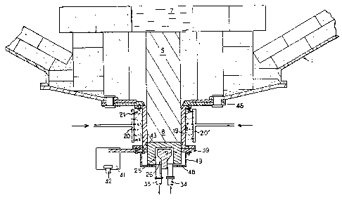
A better understanding of the invention will be had from
the following description with reference to the accompanying,
single Figure which represents a vertical sectional view of "~
a d.c, arc furnace provided with a device according to the
invention.
For a more complete description of some details of the
electric connection device which are shown in the Figure but
are not characteristics of the invention, reference
may be made if required to the aforementioned document
FR-A-2,566,984 and to the document FR-A-2,577,311 or
FR-A-2,572,873. It will merely be recalled that an
elongated metal body or bar 5 whose upper end is in contact
with the molten metal 7 extends through the bottom 1 of the
furnace. The end part 8 of the bar 5 extends beyond the end
of the furnace and is surrounded by a cooled sleeve 19. A
terminal member 9 composed of a cooled heat conductive
material extends the end part 8.
The Terminal member 9 defines a cavity 25 in which is
disposed a cooling system 26 connected to an inlet 34 and an
outlet 35 of cooling fluid.

,,; .
'Y. :' ' ';~ ~i ~s
..~ ti ;:'; :, a..~ a ~,r3
_ 4
In the illustrated embodiment, an electric connection
plate 39 is connected by at least one fin 41 to a cable 42
connected to a terminal of an electric supply. Contacts 43,
of the "spring blade" type, electrically connect the sleeve
19 to the terminal member 9.
It may be mentioned that the electric connection between
the supply and the terminal member 9 could also be achieved
directly without connection of the sleeve 19 to this supply.
A thrust-ring 48, retained below the terminal member 9
bY arms 49 fixed under the plate 39, may be provided.
In its upper part, the sleeve is maintained connected to
the shell of the furnace, for example by fixing it against a
bottom plate 46 which may be a plate composed of a non
conductive material so that it insulates the electrode from
the shell of the furnace.
According to the invention, the circulation of cooling
fluid cooling the sleeve 19 is achieved by means of racks
20, 20' of nozzles 21 which spray the fluid, for example
water under high pressure, onto the outer wall of the sleeve
in the form of fine droplets. This type of cooling is
termed "by pulverization". The cooling fluid may be mixed
with air. It is then termed "cooling by atomization'°. The
number and arrangement of the racks and of the nozzles must
be so calculated as to ensure a homogeneous cooling of the
sleeve throughout its periphery. Further, as in the other
cooling devices previously envisaged for this type of
electrode, this cooling must be sufficiently intense to

;; ;,, ;,, ,.:~ ,.~ ~~ ~a
k,J ii V~d : ii i ~.3
a 5-
avoid the complete melting of the bar 5 and in particular to
ensure that the molten front does not reach the terminal
member 9. In this way, seeping of liquid metal out of the
furnace can be avoided.
The whole of the device is enclosed in a case knot shown
in the Figure) whose function is to insulate it from the
outer medium, which avoids formation of a mist around the
furnace, and to collect and discharge the cooling fluid
after its contact with the bar.
awing to the presence of the sleeve, it is possible to
ensure a very homogeneous cooling of the bar. The sleeve
also has for function to support the bar and in this way
ensure that the solidified crust of t:he bar does not break ~
away above the molten front and allow liquid metal to escape
if the cooling fluid is unable to maintain it sufficiently
.rigid.
The calculation of the amount of heat to be extracted
from the sleeve and the determination of the number and
characteristics of the nozzles and of the rate of glow o~
cooling fluid required for this purpose are part of the
general knowledge of the person usually in charge of the
operation of this general type of bottom electrode. As a
result of the more intimate contact between the fluid and
the surface to be cooled such a device achieves, it permits
removing larger amounts of heat than the devices employing a
confined circulation of fluid heretofore employed.
It must be understood that the scope of the invention is

1,~~ s) jJ~~i ~~jf ~~~t t
- ~ -
not intended to be limited to the embodiment just described
and represented, in which the sleeve and the bar are in
constant contact. The cooling device according to the
invention is also applicable to the electrodes disclosed in
the documents FR-A-2,572,873 and FR-A-2,577,311, in which a
separating gap is provided in the cold state between the bar
and the sleeve, This gap is filled only after the bar has
undergone a certain expansion subsequent to putting the
electrode in service. Consequently, the forces exerted by
the sleeve on the bar are reduced and the life of the sleeve
is prolonged.
Furthermore, the terminal member 9 may also be cooled by
means of nozzles, this cooling being added to or substituted
for the cooling by circulation of fluid inside the terminal
member previously described and represented.

Representative Drawing
A single figure which represents the drawing illustrating the invention.
Administrative Status

2024-08-01:As part of the Next Generation Patents (NGP) transition, the Canadian Patents Database (CPD) now contains a more detailed Event History, which replicates the Event Log of our new back-office solution.

Please note that "Inactive:" events refers to events no longer in use in our new back-office solution.

For a clearer understanding of the status of the application/patent presented on this page, the site Disclaimer , as well as the definitions for Patent , Event History , Maintenance Fee  and Payment History  should be consulted.

Event History

Description Date
Inactive: IPC from MCD 2006-03-11
Time Limit for Reversal Expired 2005-10-11
Letter Sent 2004-10-12
Grant by Issuance 2001-07-24
Inactive: Cover page published 2001-07-23
Inactive: Final fee received 2001-04-10
Pre-grant 2001-04-10
Notice of Allowance is Issued 2001-01-02
Letter Sent 2001-01-02
Notice of Allowance is Issued 2001-01-02
Inactive: Approved for allowance (AFA) 2000-12-13
Inactive: IPC assigned 2000-05-08
Inactive: IPC removed 2000-05-08
Inactive: IPC assigned 2000-05-08
Inactive: First IPC assigned 2000-05-08
Letter Sent 1997-08-01
Amendment Received - Voluntary Amendment 1997-07-31
Inactive: Status info is complete as of Log entry date 1997-07-29
Inactive: Application prosecuted on TS as of Log entry date 1997-07-29
All Requirements for Examination Determined Compliant 1997-06-18
Request for Examination Requirements Determined Compliant 1997-06-18
Application Published (Open to Public Inspection) 1991-04-12

Abandonment History

There is no abandonment history.

Maintenance Fee

The last payment was received on 2000-09-21

Note : If the full payment has not been received on or before the date indicated, a further fee may be required which may be one of the following

  • the reinstatement fee;
  • the late payment fee; or
  • additional fee to reverse deemed expiry.

Patent fees are adjusted on the 1st of January every year. The amounts above are the current amounts if received by December 31 of the current year.
Please refer to the CIPO Patent Fees web page to see all current fee amounts.

Fee History

Fee Type Anniversary Year Due Date Paid Date
Request for examination - standard 1997-06-18
MF (application, 7th anniv.) - standard 07 1997-10-10 1997-09-15
MF (application, 8th anniv.) - standard 08 1998-10-13 1998-09-16
MF (application, 9th anniv.) - standard 09 1999-10-11 1999-09-16
MF (application, 10th anniv.) - standard 10 2000-10-10 2000-09-21
Final fee - standard 2001-04-10
MF (patent, 11th anniv.) - standard 2001-10-10 2001-09-19
MF (patent, 12th anniv.) - standard 2002-10-10 2002-09-16
MF (patent, 13th anniv.) - standard 2003-10-10 2003-09-15
Owners on Record

Note: Records showing the ownership history in alphabetical order.

Current Owners on Record
INSTITUT DE RECHERCHES DE LA SIDERURGIE FRANCAISE
Past Owners on Record
CHRISTIAN LEBRUN
GHISLAIN MAURER
JEAN-CLAUDE GROSJEAN
MICHEL HAMY
Past Owners that do not appear in the "Owners on Record" listing will appear in other documentation within the application.
Documents

To view selected files, please enter reCAPTCHA code :


To view images, click a link in the Document Description column. To download the documents, select one or more checkboxes in the first column and then click the "Download Selected in PDF format (Zip Archive)" or the "Download Selected as Single PDF" button.

List of published and non-published patent-specific documents on the CPD .

If you have any difficulty accessing content, you can call the Client Service Centre at 1-866-997-1936 or send them an e-mail at CIPO Client Service Centre.


Document
Description 
Date
(yyyy-mm-dd) 
Number of pages   Size of Image (KB) 
Abstract 1994-02-25 1 17
Claims 1994-02-25 1 24
Description 1994-02-25 6 201
Drawings 1994-02-25 1 27
Representative drawing 2001-07-12 1 16
Representative drawing 1999-07-18 1 22
Reminder - Request for Examination 1997-06-09 1 122
Acknowledgement of Request for Examination 1997-07-31 1 178
Commissioner's Notice - Application Found Allowable 2001-01-01 1 165
Maintenance Fee Notice 2004-12-06 1 173
Fees 2003-09-14 1 27
Correspondence 2001-04-09 1 33
Fees 1998-09-15 1 36
Fees 2001-09-18 1 33
Fees 2002-09-15 1 31
Fees 1997-09-15 1 38
Fees 1999-09-15 1 30
Fees 2000-09-20 1 30
Fees 1994-09-19 1 36
Fees 1996-09-16 1 33
Fees 1992-09-16 1 34
Fees 1995-09-18 1 34
Fees 1993-09-15 1 29