Sélection de la langue

Search

Sommaire du brevet 2027300 

Énoncé de désistement de responsabilité concernant l'information provenant de tiers

Une partie des informations de ce site Web a été fournie par des sources externes. Le gouvernement du Canada n'assume aucune responsabilité concernant la précision, l'actualité ou la fiabilité des informations fournies par les sources externes. Les utilisateurs qui désirent employer cette information devraient consulter directement la source des informations. Le contenu fourni par les sources externes n'est pas assujetti aux exigences sur les langues officielles, la protection des renseignements personnels et l'accessibilité.

Disponibilité de l'Abrégé et des Revendications

L'apparition de différences dans le texte et l'image des Revendications et de l'Abrégé dépend du moment auquel le document est publié. Les textes des Revendications et de l'Abrégé sont affichés :

  • lorsque la demande peut être examinée par le public;
  • lorsque le brevet est émis (délivrance).
(12) Brevet: (11) CA 2027300
(54) Titre français: CONNEXION ELECTRIQUE POUR PAROI DE RECIPIENT A METAL EN FUSION
(54) Titre anglais: ELECTRIC CONNECTION DEVICE INTENDED TO BE PLACED IN THE WALL OF A METALLURGICAL CONTAINER IN CONTACT WITH MOLTEN METAL
Statut: Périmé et au-delà du délai pour l’annulation
Données bibliographiques
(51) Classification internationale des brevets (CIB):
  • H01R 13/533 (2006.01)
  • C21C 05/52 (2006.01)
  • F27B 03/08 (2006.01)
  • H05B 07/06 (2006.01)
(72) Inventeurs :
  • HAMY, MICHEL (France)
  • MAURER, GHISLAIN (France)
  • LEBRUN, CHRISTIAN (France)
  • GROSJEAN, JEAN-CLAUDE (France)
(73) Titulaires :
  • INSTITUT DE RECHERCHES DE LA SIDERURGIE FRANCAISE
(71) Demandeurs :
  • INSTITUT DE RECHERCHES DE LA SIDERURGIE FRANCAISE (France)
(74) Agent: ROBIC AGENCE PI S.E.C./ROBIC IP AGENCY LP
(74) Co-agent:
(45) Délivré: 2001-07-24
(22) Date de dépôt: 1990-10-10
(41) Mise à la disponibilité du public: 1991-04-12
Requête d'examen: 1997-06-18
Licence disponible: S.O.
Cédé au domaine public: S.O.
(25) Langue des documents déposés: Anglais

Traité de coopération en matière de brevets (PCT): Non

(30) Données de priorité de la demande:
Numéro de la demande Pays / territoire Date
89 13 636 (France) 1989-10-11

Abrégés

Abrégé anglais


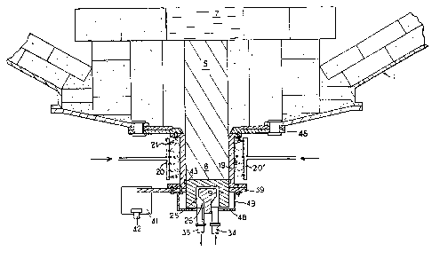
The electric connection device comprises an electrode
(5), a sleeve (19) mounted around a projecting end part (8)
of the electrode (5), and an arrangement for cooling the
sleeve (19) with a cooling fluid comprising at least one
system (20, 20') of nozzles (21) spraying cooling fluid onto
the outer surface of the sleeve (19).

Revendications

Note : Les revendications sont présentées dans la langue officielle dans laquelle elles ont été soumises.


-7-
CLAIMS
1. Electric connection device intended to be placed in
the wall of a metallurgical container or furnace containing
a molten metal mass, said device comprising:
an elongated metal body intended to be inserted in and
extend through the wall of the container so that one of its
ends is put in contact with the molten metal and the other
end constitutes an end part projecting outside the container
and connected to a terminal of an electric supply;
a sleeve composed of a material which is a good heat
conductor mounted concentrically with the projecting end
part of the body;
and means for cooling the sleeve with a cooling fluid,
such as water;
said device being characterized in that said sleeve
cooling means comprise at least one rack of nozzles which
spray the cooling fluid onto the outer wall of the sleeve.
2. Device according to claim 1, characterized in that
the cooling fluid is mixed with a gas, such as air.

Description

Note : Les descriptions sont présentées dans la langue officielle dans laquelle elles ont été soumises.


G .'' ',, 4 ~. ~'y ~: S f
~3 ~d b ~ ~
_ ~ _
ELECTRIC CONNECTION DEVICE INTENDED TO
BE PLACED IN THE WALL OF A METALLURGICAL
CONTAINER IN CONTACT WITH MOLTEN METAL
The present invention relates to an electric connection
device intended to be placed in the wall of a metallurgical
container and put in contact, by one of its ends, with a
mass of molten metal contained in the container, the other
end, cooled by a fluid, extending out of the wall of the
container and being connected to a terminal of an electric
1C1 supply
A device of this type, disclosed in the document
FR-A-2,566,98, comprises a sleeve composed of a material
which is a good heat conductor, such as copper, mounted
around the prajecting and cooled end in contact with a
y5 circulating fluid. The cooling means for the sleeve
disclosed in this document are preferably constituted by at
least one groove provided in the outer lateral surface of
the sleeve, in which the cooling fluid circulates, and a
jacket closing said groove and disposed around the sleeve,
Zp said jacket being provided with fluid inlet and outlet means
which are connected to the ends of the groove and are also
connected to a cooling fluid supply.
As an alternative, the grooves may be replaced by
channels provided inside the sleeve, but this solution has
~5 the drawback of requiring a delicate machining of the
sleeve. The previously-described solution consequently
remains the preferred one according to the cited document.

1~ ,a ,~~i ,-A ~n
a
4l ~. ~' . t . ~ d : ,v
it,! $_ i YcJ 1 2.~ 4 e.l
- 2 -
Another solution disclosed in the document
FR-A-2,621,994, comprises providing the groove or grooves,
not in the sleeve but in the inner lateral surface of the
jacket. The cost of the sleeve which no longer has to be
machined may in this way be reduced without correspondingly
reducing the effectiveness of the cooling means. The
machining of the groove therefore has only to be carried out
once in a part which does not undergo wear, which distinctly _
reduces the cost of the use of the electrode.
An object of the invention is to propose a manner of
cooling the sleeve which simplifies the overall construction
of the electrode compared with the arrangements just
described.
The invention therefore provides an electric connection
device intended to be placed in the wall of a metallurgical
container or furnace containing a molten meta l mass, said
device comprising:
an elongated metal body intended to be inserted in and
extend through the wall of the container so that one of its
2~ ends is put in contact with the molten metal and the other
end constitutes an end part projecting outside the container
and connected to a terminal of an electric supply;
a sleeve composed of a material which is a good heat
conductor mounted concentrically with the projecting end
part of the body;
and means for cooling the sleeve with a cooling fluid,
such as water;

"~' i~ '% .n '~ $ i ~~
J.n '~, s=~ c~
- 3 -
said device being characterized in that said sleeve
cooling means comprise at least one rack of nozzles which
spray the cooling fluid onto the outer wall of the sleeve.
As will have been understood, the invention consists in
cooling the electrode by a simple spraying of this fluid
onto the sleeve with no confinement of the circulation of
the fluid.
A better understanding of the invention will be had from
the following description with reference to the accompanying,
single Figure which represents a vertical sectional view of "~
a d.c, arc furnace provided with a device according to the
invention.
For a more complete description of some details of the
electric connection device which are shown in the Figure but
are not characteristics of the invention, reference
may be made if required to the aforementioned document
FR-A-2,566,984 and to the document FR-A-2,577,311 or
FR-A-2,572,873. It will merely be recalled that an
elongated metal body or bar 5 whose upper end is in contact
with the molten metal 7 extends through the bottom 1 of the
furnace. The end part 8 of the bar 5 extends beyond the end
of the furnace and is surrounded by a cooled sleeve 19. A
terminal member 9 composed of a cooled heat conductive
material extends the end part 8.
The Terminal member 9 defines a cavity 25 in which is
disposed a cooling system 26 connected to an inlet 34 and an
outlet 35 of cooling fluid.

,,; .
'Y. :' ' ';~ ~i ~s
..~ ti ;:'; :, a..~ a ~,r3
_ 4
In the illustrated embodiment, an electric connection
plate 39 is connected by at least one fin 41 to a cable 42
connected to a terminal of an electric supply. Contacts 43,
of the "spring blade" type, electrically connect the sleeve
19 to the terminal member 9.
It may be mentioned that the electric connection between
the supply and the terminal member 9 could also be achieved
directly without connection of the sleeve 19 to this supply.
A thrust-ring 48, retained below the terminal member 9
bY arms 49 fixed under the plate 39, may be provided.
In its upper part, the sleeve is maintained connected to
the shell of the furnace, for example by fixing it against a
bottom plate 46 which may be a plate composed of a non
conductive material so that it insulates the electrode from
the shell of the furnace.
According to the invention, the circulation of cooling
fluid cooling the sleeve 19 is achieved by means of racks
20, 20' of nozzles 21 which spray the fluid, for example
water under high pressure, onto the outer wall of the sleeve
in the form of fine droplets. This type of cooling is
termed "by pulverization". The cooling fluid may be mixed
with air. It is then termed "cooling by atomization'°. The
number and arrangement of the racks and of the nozzles must
be so calculated as to ensure a homogeneous cooling of the
sleeve throughout its periphery. Further, as in the other
cooling devices previously envisaged for this type of
electrode, this cooling must be sufficiently intense to

;; ;,, ;,, ,.:~ ,.~ ~~ ~a
k,J ii V~d : ii i ~.3
a 5-
avoid the complete melting of the bar 5 and in particular to
ensure that the molten front does not reach the terminal
member 9. In this way, seeping of liquid metal out of the
furnace can be avoided.
The whole of the device is enclosed in a case knot shown
in the Figure) whose function is to insulate it from the
outer medium, which avoids formation of a mist around the
furnace, and to collect and discharge the cooling fluid
after its contact with the bar.
awing to the presence of the sleeve, it is possible to
ensure a very homogeneous cooling of the bar. The sleeve
also has for function to support the bar and in this way
ensure that the solidified crust of t:he bar does not break ~
away above the molten front and allow liquid metal to escape
if the cooling fluid is unable to maintain it sufficiently
.rigid.
The calculation of the amount of heat to be extracted
from the sleeve and the determination of the number and
characteristics of the nozzles and of the rate of glow o~
cooling fluid required for this purpose are part of the
general knowledge of the person usually in charge of the
operation of this general type of bottom electrode. As a
result of the more intimate contact between the fluid and
the surface to be cooled such a device achieves, it permits
removing larger amounts of heat than the devices employing a
confined circulation of fluid heretofore employed.
It must be understood that the scope of the invention is

1,~~ s) jJ~~i ~~jf ~~~t t
- ~ -
not intended to be limited to the embodiment just described
and represented, in which the sleeve and the bar are in
constant contact. The cooling device according to the
invention is also applicable to the electrodes disclosed in
the documents FR-A-2,572,873 and FR-A-2,577,311, in which a
separating gap is provided in the cold state between the bar
and the sleeve, This gap is filled only after the bar has
undergone a certain expansion subsequent to putting the
electrode in service. Consequently, the forces exerted by
the sleeve on the bar are reduced and the life of the sleeve
is prolonged.
Furthermore, the terminal member 9 may also be cooled by
means of nozzles, this cooling being added to or substituted
for the cooling by circulation of fluid inside the terminal
member previously described and represented.

Dessin représentatif
Une figure unique qui représente un dessin illustrant l'invention.
États administratifs

2024-08-01 : Dans le cadre de la transition vers les Brevets de nouvelle génération (BNG), la base de données sur les brevets canadiens (BDBC) contient désormais un Historique d'événement plus détaillé, qui reproduit le Journal des événements de notre nouvelle solution interne.

Veuillez noter que les événements débutant par « Inactive : » se réfèrent à des événements qui ne sont plus utilisés dans notre nouvelle solution interne.

Pour une meilleure compréhension de l'état de la demande ou brevet qui figure sur cette page, la rubrique Mise en garde , et les descriptions de Brevet , Historique d'événement , Taxes périodiques et Historique des paiements devraient être consultées.

Historique d'événement

Description Date
Inactive : CIB de MCD 2006-03-11
Le délai pour l'annulation est expiré 2005-10-11
Lettre envoyée 2004-10-12
Accordé par délivrance 2001-07-24
Inactive : Page couverture publiée 2001-07-23
Inactive : Taxe finale reçue 2001-04-10
Préoctroi 2001-04-10
Un avis d'acceptation est envoyé 2001-01-02
Lettre envoyée 2001-01-02
Un avis d'acceptation est envoyé 2001-01-02
Inactive : Approuvée aux fins d'acceptation (AFA) 2000-12-13
Inactive : CIB attribuée 2000-05-08
Inactive : CIB enlevée 2000-05-08
Inactive : CIB attribuée 2000-05-08
Inactive : CIB en 1re position 2000-05-08
Lettre envoyée 1997-08-01
Modification reçue - modification volontaire 1997-07-31
Inactive : Renseign. sur l'état - Complets dès date d'ent. journ. 1997-07-29
Inactive : Dem. traitée sur TS dès date d'ent. journal 1997-07-29
Toutes les exigences pour l'examen - jugée conforme 1997-06-18
Exigences pour une requête d'examen - jugée conforme 1997-06-18
Demande publiée (accessible au public) 1991-04-12

Historique d'abandonnement

Il n'y a pas d'historique d'abandonnement

Taxes périodiques

Le dernier paiement a été reçu le 2000-09-21

Avis : Si le paiement en totalité n'a pas été reçu au plus tard à la date indiquée, une taxe supplémentaire peut être imposée, soit une des taxes suivantes :

  • taxe de rétablissement ;
  • taxe pour paiement en souffrance ; ou
  • taxe additionnelle pour le renversement d'une péremption réputée.

Les taxes sur les brevets sont ajustées au 1er janvier de chaque année. Les montants ci-dessus sont les montants actuels s'ils sont reçus au plus tard le 31 décembre de l'année en cours.
Veuillez vous référer à la page web des taxes sur les brevets de l'OPIC pour voir tous les montants actuels des taxes.

Historique des taxes

Type de taxes Anniversaire Échéance Date payée
Requête d'examen - générale 1997-06-18
TM (demande, 7e anniv.) - générale 07 1997-10-10 1997-09-15
TM (demande, 8e anniv.) - générale 08 1998-10-13 1998-09-16
TM (demande, 9e anniv.) - générale 09 1999-10-11 1999-09-16
TM (demande, 10e anniv.) - générale 10 2000-10-10 2000-09-21
Taxe finale - générale 2001-04-10
TM (brevet, 11e anniv.) - générale 2001-10-10 2001-09-19
TM (brevet, 12e anniv.) - générale 2002-10-10 2002-09-16
TM (brevet, 13e anniv.) - générale 2003-10-10 2003-09-15
Titulaires au dossier

Les titulaires actuels et antérieures au dossier sont affichés en ordre alphabétique.

Titulaires actuels au dossier
INSTITUT DE RECHERCHES DE LA SIDERURGIE FRANCAISE
Titulaires antérieures au dossier
CHRISTIAN LEBRUN
GHISLAIN MAURER
JEAN-CLAUDE GROSJEAN
MICHEL HAMY
Les propriétaires antérieurs qui ne figurent pas dans la liste des « Propriétaires au dossier » apparaîtront dans d'autres documents au dossier.
Documents

Pour visionner les fichiers sélectionnés, entrer le code reCAPTCHA :


Pour visualiser une image, cliquer sur un lien dans la colonne description du document. Pour télécharger l'image (les images), cliquer l'une ou plusieurs cases à cocher dans la première colonne et ensuite cliquer sur le bouton "Télécharger sélection en format PDF (archive Zip)" ou le bouton "Télécharger sélection (en un fichier PDF fusionné)".

Liste des documents de brevet publiés et non publiés sur la BDBC .

Si vous avez des difficultés à accéder au contenu, veuillez communiquer avec le Centre de services à la clientèle au 1-866-997-1936, ou envoyer un courriel au Centre de service à la clientèle de l'OPIC.


Description du
Document 
Date
(aaaa-mm-jj) 
Nombre de pages   Taille de l'image (Ko) 
Abrégé 1994-02-25 1 17
Revendications 1994-02-25 1 24
Description 1994-02-25 6 201
Dessins 1994-02-25 1 27
Dessin représentatif 2001-07-12 1 16
Dessin représentatif 1999-07-18 1 22
Rappel - requête d'examen 1997-06-09 1 122
Accusé de réception de la requête d'examen 1997-07-31 1 178
Avis du commissaire - Demande jugée acceptable 2001-01-01 1 165
Avis concernant la taxe de maintien 2004-12-06 1 173
Taxes 2003-09-14 1 27
Correspondance 2001-04-09 1 33
Taxes 1998-09-15 1 36
Taxes 2001-09-18 1 33
Taxes 2002-09-15 1 31
Taxes 1997-09-15 1 38
Taxes 1999-09-15 1 30
Taxes 2000-09-20 1 30
Taxes 1994-09-19 1 36
Taxes 1996-09-16 1 33
Taxes 1992-09-16 1 34
Taxes 1995-09-18 1 34
Taxes 1993-09-15 1 29