Note: Descriptions are shown in the official language in which they were submitted.
RCA 85,762
-1- 202733~
VIDEO PANNING SYSTEM
FOR WlDESCREEN T~L~VISION
This invention concerns video panning apparatus for
S use with a widescreen television system which is compatible with
a standard television system having a smaller image aspect ratio.
A conventional television receiver, such as a receiver
in accordance with the NTSC broadcast standard adopted in the
United States and elsewhere, has a 4x3 aspect ratio (the ratio of
10 the width to the height of a displayed image). Recently, there has
been interest in using higher aspect ratios for television systems,
such as 2xl, 5x3 or 16x9, since such higher aspect ratios more
nearly approximate or equal the aspect ratio of the human eye
than does the 4x3 aspect ratio of a standard television receiver
1 5 display.
It is desirable for widescreen television systems to be
compatible with standard television receivers to facilitate the
widespread adoption of widescreen systems. One known
compatible widescreen television system is described by
20 ~1. A. Isnardi et al. in an article "Encoding for Compatibility and
Recoverability in the ACTV System", published in IEE~E
Transactions on Br~adcastin~, Vol. BC-33, December 1987, and in
U.S. patent 4,855,811 of M. A. Isnardi. This known system
develops a single channel compatible widescreen television signal
2 5 which produces a standard 4x3 aspect ratio display when received
by a conventional television receiver, and which produces a
widescreen Sx3 aspect ratio display when received by a
widescreen television receiver.
The widescreen television system proposed by Isnardi
30 was described in the context of a system wherein the compatible
4x3 main image area is horizontally centered on the widescreen
image. However, when the main image action is off-center, it may
be desirable for the compatible 4x3 NTSC display to follow the
main action. That is, it may be desirable to steer the standard 4x3
3 5 display area so that it follows the main image action. Such a
procedure is well known and is commonly referred to as
"panning" or "pan and scan", wherein a panning window follows
the main image action. To implement pannlng, an operator such
as a studio technician monitors the widescreen television signal
, . . ' . . . ', ~ :
, ~ . . . . . . .
. .; , .. . . ... . . . .
-. .. .
,. .. ~
. .
.. ~ i - . . .: :
::
RCA 85,762 2 ~ 2 ~ 3 3 ~
-2-
image before transmission, and manually controls the panning
window so that it follows the main image action. Such control
simultaneously produces a panning control signal representative
of the position of the panning window relative to a nominal center
position The control signal can be transmitted with the television
signal, e.g., in the vertical blanking interval.
~n accordance with the principles of the present
inv~ntion, panning is accomplished by performing a so called
circular-shift operation on a widescreen video signal at a
transmitter, followed by an inverse circular-shift on a widescreen
video signal at a receiver. A panning offset signal indicates the
amount of displacement of a panning window from a reference
position. In an illustrative embodiment, when a panning window
with a 4x3 aspect ratio is shifted left for example, a portion of the
right side panel information is "cut" and "pasted" adjacent to the
left side panel information so that the 4x3 panning window
remains centered for display purposes. A standard aspect ratio
receiver processes and displays the centered 4x3 panning window
information normally, unaffected by the panning operation at the
2 0 widescreen source. A reverse circular-shift operation is
performed at a widescreen receiver to re-establish the original
wide~creen spa~i~l forma~.
pescription of the l:)rawin~s
FIGURE 1 contains pictorial representations of the
2 5 circular-shift panning process according to the present invention.
FIGURE 2 shows apparatus suitable for performing
barrel-shift and inverse circular-shift panning according to the
present invention.
FIGURE 3 illustrates a portion of a widescreen
3 0 television signal encoding (transmitter) system including panning
apparatus according to the invention.
FIGURE 4 illustrates a portion of a widescreen
television signal decoding (receiver) system including panning
apparatus according to the invention.
3 5 The disclosed panning system redefines what the
encoder and decoder process as center (main) panel information
and side panel information. Specifically, in the disclosed panning
. .
. ~ .
2~2'^~33~
RCA 85,762
-3 -
system the main panel image information is the image
information in the panning window.
In FIGURE 1, pictorial (A) illustrates a widescreen
image (e.g., with a 16x9 or 5x3 aspect ratio) with a standard 4x3
5 aspect ratio panning window (main panel area) showing a partial
pan to the left. That is, the panning window is shifted left. A
panning offset signal representative of the amount by which the
panning window is shifted horizontally is generated for each
frame of widescreen source material in this example. The panning
10 offset is generated by an operator at a television studio using a
manual control to follow the main scene content or action. The
panning offset control signal can be transmitted to a decoder in a
receiver in a variety of ways, such as a digitally encoded signal on
a line in the vertical blanking interval, for example.
As shown in pictorial (B) of FIGURE 1, at the encoder
the widescreen source image is circular-shifted in the opposite
direction so as to keep the image in the panning window centered
on the active line. As a result, the widescreen source including
the main panel information is shifted horizontally opposite to the
2 0 panning direction. Thus, in the illustrated example, the main
panel image is shiftcd right when the panning window is shifted
left. To accomplish this, thc portion of the right side panel image
falling outside the active image line after shifting right is "cut" and
"pasted" (as R') into the gap produced next to the left side panel,
2 5 thereby re-centering the 4x3 main panel image as illustrated.
The remainder of the compatible widescreen encoding
process operates independently of the panning operation, and
assumes a centered main panel component and equal width side
panel components. To produce an encoded NTSC compatible
3 0 widescreen TV signal, low frequency side panel information is
time compressed and placed in the horizontal line overscan
regions which are normally not intended to be seen by a viewer,
as discussed in U.S. patent 4,855,811 for example and as
illustrated by pictorial (C) of FIGURE 1. The encoder processes the
3 5 input signal symmetrically, and the time compressed side panel
information remains hidden from view even when the 4x3 portion
of the image is panned left or right. Wher. the panning window is
, .
,
,, .
~ . ` , ~ , .
- .. . . ,. ~ ,
RCA 85,762 2 ~ 2 7 3 3 ~
-4 -
offset, one of the overscan regions (the left region in this example)
will contain both left and right side panel information.
In the process of encoding the widescreen image of
pictorial (B) to produce the NTSC compatible image signal
5 reprcsented by pictorial (C), ~he side panel low frequency
information is time compressed by a factor of 5 or 6, and the main
panel image area is slightly time expanded (e.g., by a factor of
about 1.3). The specifics of this procedure are found in previously
mentioned U S. patent 4,855,811. The spatial relationships of
10 pictorials (A), (B) and (C) of FIGURE 1 are drawn substantially tO
scale, but the pictorials do not show identical time scales along the
horizontal axis. In each case the width of the entire image (one
horizontal active scanning line) spans approximately 52
microseconds .
The described circular-shift panning technique using
the "cut" and "paste" operation advantageously prevents the area
occupied by either side panel region from becoming excessively
wide such as in the case of panning full left or full right. In the
absence of the disclosed circular-shift technique, the amount of
20 side panel information produced in such a case could be sufficient
to ex~end beyond the overscan regions into the active display
regionJ even after time compression of the side panel information
The disclosed technique prevents this result by substantially
equalizing the width of the side panel information on either side
2 5 of the main panel, thereby keeping the panning window (main
panel) centered. At the decoder, the widescreen components are
recovered, and an inverse circular-shift operation is performed to
spatially realign the image to its original form.
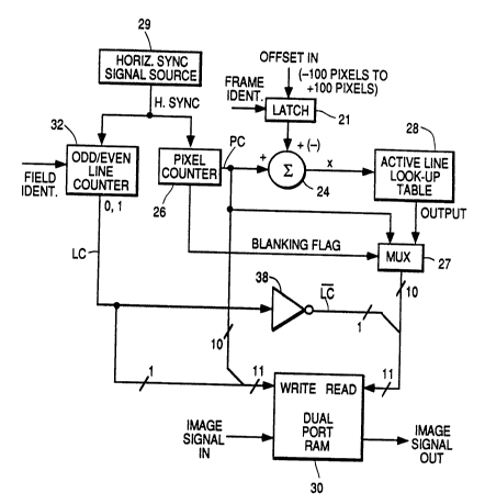
FIGURE 2 illustrates apparatus which can be used to
3 0 implement the circular-shift operation at the encoder. With a
small modification as will be described, the apparatus of FIGURE 2
can perform the inverse circular-shift operation at a decoder. A
panning OFFSET control signal in binary form is applied to a &ame
latch 21 where it is stored for the duration of an image frame. In
3 5 this example the video signal is in interlaced form so that each
frame comprises two image fields, with odd fields containing odd
numbered image lines and even fields containing even numbered
image lines. The OFFSET signal represents the amount of
~, . .. ..
. ~ .. - ~ ., .
RCA 85,762 2 Q 2 ~ ~ 3 ~
horizontal image shift during panning, and in this example can
represent a panning offset of plus or minus 100 pixels from a
prescribed centered panning window position. A frame identifier
signal (FRAME IDENT) controls the operation of latch 21. Each
horizontal line illustratively comprises 910 pixels. Pixels 0-99
encompass the horizontal blanking interval including the sync
interval, and pixels 100-909 constitute the active image line
interval.
The OFFSET signal appears at the output of latch 21 for
a frame period, after which it is up-dated for the next image
frame. The OFFSET signal is applied to a non-inverting (+) input of
a combiner 24, another non-inverting (+) input of which receives a
binary output signal PC from a pixel counter 26. Pixel counter 26
provides an output 0-909 pixel count for every odd and even
horizontal scanning line. Counter 26 is a free-running device
which is reset at the end of each horizontal line in response to a
horizontal sync pulse HORIZ SYNC derived from horizontal
synchronizing information present during horizontal blanking
intervals of the television signal.
2 0 When the panning window is cen~ered, i.e., whcn thcre
is no panning off~et and the output from latch 21 is zero, the
value of output signal X from combiner 24 equals the value of an
OUTPUT signal from an active line look-up table (PROM) 28. Unit
28 maps values of X that fall off one edge of the active line into
values at the other end of the line. Unit 28 passes values of X that
fall within the active line (pixels 100-909). The output signal
from unit 28 is conveyed via a multiplexer (MUX) 27 to a READ
address port of a dual port RAM 30. A WRITE address port of
RAM 30 receives output signal PC from pixel counter 26. In the
3 0 case of a zero panning offset the WRITE address signal is identical
to the READ address signal, since the output signal from combiner
24 is equal to the output signal from look-up table 28. The WRITE
address port of RAM 30 also receives a control signal from an
odd/even line identifier unit 32. The output of unit 32 changes
3 5 state from one horizontal image line to the next, e.g., a "0" binary
output state signifies an odd numbered line and a " I " binary
output state signifies an even numbered line. Unit 32 is toggled to
change its output state at the start of every line in response to the
.
. - ... .
.. ~
RCA 85,762 2 Q 2 7 3 3 ~
-6 -
HORIZ SYNC signal, and also in response to a field identifier signal
(FIELD IDENT) which indicates the presence of an odd or an even
image field as known. The field identifier signal assures that the
output of unit 32 is correct for odd and even fields, e.g., a "0" state
5 will be produced for odd lines associated with odd fields. With
identical signals applied to the WRIT~ and READ address ports of
RAM 30, the output signal from RAM 30 corresponds to the input
signal of RAM 30, i.e., no circular-shift compensation is provided
since there is no panning.
MUX 27 and the associated BLANKING FLAG signal
derived from blanking interval sensing circuits associated with
counter 26 are optional and are used if it is desired to pass the
horizontal blanking interval without being subject to the panning
operation. The BLANKING FLAG signal encompasses pixels 0-99
and causes MUX 27 to pass the blanking interval signal component
from the output of counter 26 directly. Passing the blanking
interval information without a panning offset may be useful
where, for example, it is desired to retain a reference point such
as an edge of the horizontal synchronizing pulse contained in the
2 n blanking interval,
Considcr now thc casc of an offsct introduced by pan
and scan opcration, i.e., the main image action is no longer
centered. Recall that, in this example, pixels 0-99 of each
horizontal scan line constitute the horizontal blanking interval,
2 5 and pixels 100-909 constitute the active image interval.
In the case of a pan to the right, the OUTPUT signal
from active line look-up table 28 as applied to RAM 30 via MUX
27 begins when the output of pixel counter 26 is representative of
pixel 100, the beginning of the active line interval. A pan to the
right is assigned a positive (+) polarity, so that a 100 pixel pan to
the right is associated with a +100 OFFSET value from the output
of latch 21. The value of the OUTPUT signal from look-up table 28
as a function of X can be expressed as
MOD (X, LP-FP+1) + FP, where
3 5 MOD (Modulus) is the remainder when X is divided by
the value LP-FP+1,
X = PC + OFFSET,
FP is the first active pixel (100 in this example), and
.
- ~ ,
RCA 85,762 ~ 3 2
LP is the last active pixel (909 in this example).
This expression can be rewritten as MOD (X, 810) + 100. Thus the
value of the output signal from look-up table 28 as applied to
RAM 30 at the beginning of the active line interval corresponds to
pixel 200, i.e., the original first active pixel value (100) plus the
panning offset ~100). The READ address of RAM 30 receives from
look-up table 28 a signal representative of the total active image
pixel values, from 200 through 909, followed by pixel values 100
through 199. Pixel values 100-199 are those which have been
"cut" from the left side panel area and "pasted" onto the right side
panel area to keep the panning window centered Thus the image
output signal from RAM 30 comprises pixels 200-909 followed by
pixels 100-199
In the case of a pan to the left as illustrated in FIGURE
1, the output signal from look-up table 28 as applied to RAM 30
via MUX 27 commences when the output of pixel counter 26 is
representative of pixel 810. A pan to the left is assigned a
negative (-) polarity, so that a 100 pixel scan to the left is
associated with a -100 OFFSET value from the output of latch 21.
The va1ue of the output signal from look-up table 28 as a function
of X Is determined in accordance with thc expression given above.
In this case the READ address port of RAM 30 receives from look-
up table 28 via MUX 27 a signal representative of the total active
image pixel values, from pixels 810 through 909 followed by
2 5 pixels 100 through ~09. Pixels 810-909 are those which have
been "cut" from the right side panel area and "pasted" onto the
left side panel area to keep the panning window centered. Thus
the image output signal from RAM 30 comprises pixels 810-899
followed by pixels 100-809.
An inverter 38 is switched at the horizontal line rate
to cause a toggle between the memory read and memory write
functions of dual-port RAM 30. The output of line counter 32 (LC)
represents the most significant bit (MSB) of the WRITE address
signal input to RAM 30, and its complement ( LC ) is the MSB of
3 5 the READ address signal input to RAM 30. Thus, while new data is
being written into one-half of dual port RAM memory, old,
circularly shifted data is being read out of the other half of dual
port RAM memory.
..
;:
,: :
- 8 - RCA 85,762 ? ~ 2 ;~ 3 e;
FIGURE 3 is a block diagram of a system for encoding
an NTSC compatible widescreen signal. With the exception of the
panning function, this system corresponds to that described in U.S.
patent 4,855,811 - Isnardi. Briefly, a 525 line widescreen
5 ~rogressive scan signal source 40 (e.g., a video camera) provides
analog widescreen color image components R, G and B to a matrix
42 which converts these components into a luminance component
Y, and I and Q color difference components. The Y, I and Q
components are converted from analog to digital form by analog-
10 to-digital converter networks 44. The digital Y, I, Q components
from converter 44 are filtered individually by separate vertical-
temporal (V-T) low pass filters in a unit 46. The Y, I and Q
signals from filter network 46 are respectively converted from
progressive scan to interlaced scan signals Y', I' and Q' by means
15 of units 50, 51 and 52.
Signals Y', I' and Q' are respectively processed by
panning units 54, 55 and 56, each being of the type shown in
FIGURE 2. Each of the panning units responds to an OFFSET
control signal from a source 57, e.g., a control device opcr~ted by a
20 ~udio technician. The OPFSET signal from source 57 is in digital
form. The OFFSET signal is encoded in the vertical b!anking
interval by means of a vertical interval encoder 60. Signals Y", I"
and Q" from panning units 54, 55 and 56 are format encoded by
means of a side panel and center panel signal processor 58 as
25 described in greater detail in U.S. patent 4,855,811. An output
signal N from processor 58 is a 525 line, 2:1 interlaced NTSC signal
with a 4x3 aspect ratio corresponding to the panning window, and
having time compressed low frequency side panel information
disposed in horizontal overscan regions which are normally not
3 0 visible to a viewer. An output signal M from processor 58 is an
auxiliary signal comprising an auxiliary subcarrier modulated
with high frequency side panel information. Signals M and N are
combined by an adder 59 to form a 4.2 MHz baseband television
signal which is compatible with both standard NTSC receivers and
35 widescreen receivers. After insertion of the panning OFFSET
control signal into the vertical blanking interval via encoder 60,
the compatible widescreen signal is converted to analog form by a
`, .: ~,
, . ~.
~ ,
.. . ;. . .
.~ .. . . . ..
RCA 85,762
9 2~33~
digital-to-analog converter 61. This signal modulates an RF
carrier in a unit 62 and is broadcast via an antenna 64.
FIGURE 4 illustrates a portion of a widescreen receiver
for receiving the compatible widescreen signal broadcast by the
5 system of FIGURE 3. The receiver system of FIGURE 4 is also
de~cribed in detail in U.S. patent 4,855,811, except for the panning
function.
A compatible widescreen interlaced television signal is
received by an antenna 70 and applied to an antenna input of an
10 NTSC receiver 72. Receiver 72 processes the compatible
widescreen signal in normal fashion to produce an image display
with a 4x3 aspect ratio, with the encoded widescreen side panel
information being unseen by a viewer. The signal received by
antenna 70 is also applied to a widescreen receiver, shown in
15 block diagram form, for displaying a video image with a wide
aspect ratio, e.g., Sx3 or 16x9. The received signal is processed by
an input unit 71 including radio frequency (RF) tuner and
amplifier circuits, a synchronous video demodulator for
recovering baseband video information, and analog-to-digital
20 (~DC) converter circuits for producing a baseband video signal in
digi~al form.
Si~nals M and N are recovered by an intraframe
processor 75 which averages and differences image lines 262
horizontal lines apart within image frames. Signals M and N are
25 decoded into constituent widescreen components Y", I" and Q" by
means of a side-center panel signal processor 78. These signals
are respectively processed by panning units 80, 81 and 82, which
respond to the OFFSET control signal which is recovered from the
vertical blanking interval by a vertical interval decoder 83.
3 0 Panning units 80, 81 and 82 are each similar to the apparatus
shown in FIGURE 2, except that the input of combiner 24 which
receives the output signal from latch 21 is an inverting (-) input,
whereby combiner 24 acts as a subtracter. Panning units 80, 81
and 82 perform the inverse of the barrel-shift operation
3 5 performed at the encoder, so that the image information of
widescreen components Y, I and Q exhibits the original spatial
alignment. That is, the panning window exhibits the same spatial
alignment relative to the remaining widescreen information as
R(~A 85 ,762 ~ J ~
- 1 0 -
existed at the widescreen source. Standard NTSC receivers
process the 4x3 aspect ratio main panel information normally,
unaffected by the panning operation at the widescreen signal
source.
Output signals Y', I' and Q' from panning units 80, 81
and 82 are converted from interlaced to progressive scan form by
converters 84, 85 and 86 respectively, for producing signals Y, I
and Q. These signals are converted to analog form by a digital-to-
analog converter 88 before being applied to a signal processor and
10 matrix amplifier 90 The video signal processor portion of unit 90
includes signal amplifying, DC level shifting, peaking, brightness
control, contrast control and other conventional video signal
processing circuits. The matrix amplifier portion of unit 90
combines luminance signal Y with color difference signals I and Q
15 to produce color signals R, G and B These color signals are
amplified by display driver amplifiers in unit 90 to a level
suitable for directly driving a widescreen color image display
device 92, e g, a widescreen kinescope.
, , ~
. . . . . ~ . . .. ... ..
, ., .
~ . ~
.~ ~ ~ . . . . . . . .. . .. .