Note: Descriptions are shown in the official language in which they were submitted.
SELECTIVELY COOLED OR HEATED SEAT
AND BACKREST CONSTRUCTION
l BACKGROUND OF THÆ INVENTION
1. Field of the Invention
The present invention relates generally to a
seat and backrest construction, and, more particularly,
to such a seat and backrest construction provided with
temperature conditioned air for selectively cooling or
warming the user, as desired.
2. Background of the Invention
In co-pending U.S. patent application Serial
No. 07/272,518, COOLING AND HEATING SEAT PAD, filed
November 17,1988 by Steve Feher there is described a
seat pad construction which can be located on a
preexisting seat, or consolidated integrally into a
seat, which has an internal plenum supplied with air
from a Peltier powered unit that can be cooled or
heated, as desired. Although the described device
functions adequately for the desired purpose of cooling
and heating, in order to achieve optimal operation it
was thought necessary that comfort would have to be
sacrificed. Also, under certain conditions excessive
accumulation of condensate was found to occur with the
potential of spilling and damaging vicinity of use.
3 l~
1 SUMMARY OF THE INVENTION
In accordance with the present invention there
is provided a seat and backrest construction enclosing a
plenum into which temperature conditioned air passes
generated by a Peltier or other thermoelectric device
located under the seat or otherwise conveniently
situated. In accordance with a first version, ~he
covering on the outer surface facing the user is multi-
layered consisting of, from the inside out, a metal
and/or plastic mesh layer, a sheet of a synthetic
elastomer or natural rubber material having a plurality
of openings formed therethrough which material has the
special properties of being able to provide exceptional
dissipation of forces, shocks and vibrations normally
encounter~d in a moving automotive vehicle, and an outer
diffusion cover layer constructed of any suitably
permeable fabric material or perforated leather. It is
contemplated that the diffusion layer ~e eleasably
secured to the seat and backres~ by a hook and loop
connector, for example, so that on becoming damaged or
worn it can be replaced instead of having to replace the
entire unit. The material forming the perforated sheet
has such load distribution, shock and vibration
absorption properties as to enable using a relatively
thin sheet that will readily allow thermal transfer via
convection primarily, and, to a lesser extent, by
conduction.
The internal plenum of both the seat and
backrest is formed by a plurality of metal wire
helically wound springs, oval in cross-section, which
are closely spaced presenting a resilient supporti-ng
force to transversely applied forces. These springs
maintain the plenum for temperature conditioned air even
1 when subjected to the weight of the user sitting or
leaning against them.
An alternative embodiment of the invention
contemplates replacing the oval metal wire springs with
a plurality of molded, flexible plastic tubes having
perforated walls which provide sufficient rigidity to
maintain the plenum for the temperature conditioned air
and also sufficiently flexible to form a comfortable
seat and backrest while promoting thermal transfer via
convection between the warm air at the surface of the
user's body and clothing and the cool de-humidified air
flowing past the user on the inside of the plenum when
in the cooling mode. Heat transfer direction is
reversed in the heating mode.
In yet another version, the seat and backrest
portions are incorporated into an integral seat
arrangement with conditioned air being supplied
separately in prorated amounts. The seat part includes
a lower base of multi-density foam over which a
suspension of plenum coils of either the metal wire kind
or the hollow plastic tubes is located. ~ layer of
copper or aluminum cloth is positioned over the
suspension coils and a layer of a more open plastic mesh
is covered by a force absorbing and distributing
perforated elastomer layer and outer convection
diffusion layer. The conditioned air is added to the
enclosed plena of both the seat and backrest. There not
only is added comfort from the multi-density foam, but
the metal and plastic mesh serves to distribute the
user's weight uniformly over the seat and backrest
surface while allowing convection and conduction thermal
transfer to occur efficiently.
As yet another alternative, instead of the
perforated elastomer layer, a pad is constructed of a
pair of plastic sheets arranged in facing relationship
2 ~
1 and heat sealed at a number of points to provide a
number of openings while preventing fluid leakage out of
the bag. The enclosed bag is filled with a so called
Flourinert liquid which possesses high thermal transfer
properties. Also, at the sealed points the openings
formed allow thermal transfer to occur via air
convection between the user ancl the hot (cold) air
within the plena.
To reduce condensate collection in the
1~ conditioning unit, a felt strip has one end in contact
with a felt pad in the main exchanger cover which then
becomes a condensate trap, and the opposite is
positioned within the air stream at the auxiliary
changer. Acting as a wick the felt moves the condensate
liquid by capillary force into the air stream which
takes it away preventing undue liquid accumulation
within the main exchanger housing which is undesirable
since excessive condensate accumulation reduces main
exchanger performance.
~ESCRIPTION OF THE DRAWING
FIG. 1 is a perspective view of the seat and
backrest of the present invention;
FIG. 2 is a side elevational, sectional view
taken along the line 2-2 of FIG. l;
FIG. 3 is a partially fragmentary sectional
view taken through the conditioned air entrance point
along line 3-3 of FIG. l;
FIG. 4 is a perspective, partially sectional
view of a force absor~ing and heat transfer sheet of the
present invention;
FIGS. 5a and 5b show perspective and sectional
views of an alternative form of force absorbing and heat
transferring s,heet;
1 FIG. 6 is an end elevational, sectional view
taken along line 6-6 of FIG. l;
FIG. 7 is an end elevational, sectional view
similar to FIG. 6 of a further embodiment of the present
invention;
FIG. 8 is a view similar to FIG. 7 of a still
further embodiment of the present invention;
FIG. 9 is an enlaryed, perspective view of a
alternate suspension coil of the invention;
FIG. 10 is an end elevational, sectional view
taken along the line 10-10 of FIG. 9;
FIG. 11 is a sectional, elevational view of an
alternate form of seat and backrest construction showing
additional padding;
FIG. 12 is a three way valve for use in
directing proportioned amounts of air to the seat and
backrest;
FIG. 13 is a sectional ! elevational view taken
along the line 13-13 of FIG. 1;
FIG. 14 is a side elevational sectional view of
a two-piece embodiment of the present invention; and
FIG. 15 is a sectional view of an improved
condensate trap.
DESCRIPTION_OF pREFERRED EMBODI~ENTS
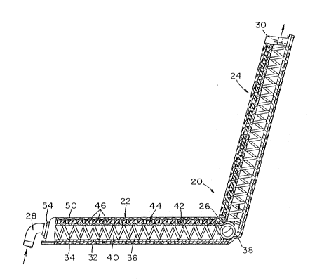
Turning now to the drawings and particularly
FIG. 1 there is shown a seat and backrest construction
in accordance with the present invention identified
generally as 20. More particularly, ~he construction ~0
includes generally a seat 22 and backrest 24 joined
along a fold line 26. As will be shown, the interior of
the seat and .backrest forms a single intercommunicating
air plenum th:rough which pressurized conditioned air
entering from a conduit 28 passes and finally leaves the
backrest at exit points 30. As will be clarified later
~ ~ 2 'i' ~
1 herein, the primary mode of operation is to take the
cooling or warming effect of the conditioned air which
passes through the plenum and spread it out over the
entire back surface and seat surface for achieving a
corresponding warming/cooling of the user. A preferable
air conditioning unit is the Peltier powered unit
described in the referenced Feher patent application.
For the ensuing description of the details of
the seat and backrest 20, reference is now made
simultaneously to FIGS. 2 through 4 and 6. Since the
seat and backrest construction is substantially the same
for both, only the seat will be fully described with
differences of the backrest noted later. The seat 22
includes a flexible and imperforate lower sheet 32 over
which a fabric, or other generally aesthetically
pleasing outer surface covering 34 may be formed. Since
the cooling/heating effect is not required on the seat
lowermost and backrest outer surfaces, ~he sheet 32 and
covering 34 should be impervious to air passage and
preferably be a relatively poor heat conductor.
The essential support for the seat includes a
plurality of metal wire spring coils 36 which have been
flattened somewhat in their cross-section (FIG. 6) so
that they appear oval. Accordingly, as shown in FIG. 6
a plurality of these coils are located closely adjacent
to one another and rest on the upper surface of the
flexible sheet 32 with their broader cross-sectional
dimension maintained parallel to the sheet 32. Along
the juncture between the backrest and the seat(some~imes
referred to as the "bite line"), there is a single coil
38 to define the hinge between the seat and backrest
(portable folding cushion and/or one-piece bucket type
seats) and allow free internal air flow through the bite
line, or hinge line area, by preventing collapse. The
2 ~
1 springs collectively maintain an air plenum 40
throughout the seat, and the backrest as well.
A metal and/or plastic mesh layer 42 completely
covers the upper surface of the coils 36 and 38.
5 Ou~wardly or above the mesh layer 42 is a sheet 44 of an
elastomer having exceptional force, vibration and shock
absorbing properties and inclucling a plurality of
openings 46 extending completely the material (FIG. ~)
while leaving a portion 48 towards the front edge center
devoid of openings which would normally be located
between the legs of a user of the device. The
correspondins sheet 44 for the backrest does not have
anything similar to portion 48, but instead has openings
uniformly existing over the entire sheet.
A preferred and advantageous form of the laysr
42 is obtained by using a first layer of copper or
aluminum clo~h of approximately 80 x 80 mesh and wire
diameter of approximately 0.005 inches, over which is
laid a layer of a plastic mesh (approximately 9 x 9) of
0.015 - 0.020 inches filament diameter.
The material best utilized for making a sheet
44 is sold under the trade designation Sorbothane which
has the useful physical properties of behaving as a
viscous fluid when subjected to force, shock, or
2; vibration. The plastic acts to absorb the "feel" of the
coils and yet can be made thin enough so as not to
impede ready heat transfer. In addition, the openings
in the elastomer sheet 44 allow convection to take place
so that the use will experience cooling and
dehumidification or warming, depending upon which mode
of use is chosen.
An uppermost layer 50 made of any air permeable
fabric or other suitable convection diffusion material,
including perforated leather, covers the elastomer sheet
44. The front or leading edge portion of the seat
~ ~ 2 ~
1 includes a fitting 52 into which a complementary fitting
54 can be releasably snapped, the latter being received
on the end of a conduit 56 which interconnects with a
supply of pressurized conditioned air.
Returning to FIG. 1, there is a turned back
portion 58 of the diffusion layer 50 showing a preferred
manner of releasably affixing t:he diffusion layer via a
hook and loop connector (Velcro) 60. More particularly,
the hook part 62 is secured to the border of the
diffusion layer and the loop part 64 is secured to the
edge portion of the plate 32. In this manner, a
diffusion layer may be readily replaced individually
rather than requiring replacement of the entire seat and
backrest.
FIG. 7 depicts an alternate embodiment of seat
construction which is substantially more comfortable
than the first described version. Specifically, a lower
support sheet 66 receives a plurality of spring coils,
or perforate plastic tubes 92 which can be identical to
the coils ~6 of FIG. 2. The spring coils are arranged
in parallel side-by-side relation and over which a
plastic mesh or wire mesh layer 68 is received and
stapled or otherwise secured to the underlying plate 66
in between each of the coils thereby serving to firmly
position the springs in place. An outer diffusion layer
70 is then formed over the entire assembly and can
include ornamentation, as desired. The entire seat
assembly is located on foam pad 72 which, in turn, is
positioned on a plurality of transversely extending
straps 74 that are spring-loaded at their edges for
resiliency and comfort, as well as support. Bolsters 78
can be added at each side to position the body over the
coils 36.
A still further form of the invention is that
shown in FIG. R in which a main feature is the
?~
1 elimination of the spring coils 36. In particular, the
seat assembly is shown mounted on brackets 80 arranged
on the bottom adjacent each side, and, as in the FIG. 7
embodiment, includes bolsters 82 at each side. A hollow
plenum 84 is defined by an interconnected sidewall and
bottom wall shell 86 made of molded vinyl, for example,
over the top of which a plurality of flexible plastic
straps 88 woven in tension define an upper surface for
the plenum and through which convection can readily
occur. Over the plastic straps there is located first a
plastic/metal mesh 90 and finally a diffusion layer 92.
Turning now to FIGS. 9 and 10 there is shown a
substitute resilient support for the spring coils 36 of
the earlier described embodiments. As shown there, each
spring element 92, which dimensionally can be
substantially identical to a coil 36 previously
described, consists of a hollow cylindrical body 94
constructed of molded plastic or extruded plastic having
a plurality of openings 96 distributed over its surface.
This member not only possesses a suitable springlike
flexibility for forces directed transversely of its
longitudinal dimensions, but also the air can readily
pass along the central bore as well as through the
openings in its side wall. These coils can be used
wherever the coil springs are used in a seat or backrest
of the described embodiments.
FIG. 11 shows in section a further form of seat
(and backrest) in which a foam layer 98 is laid down on
a rigid sheet 100 and covered by a similar flexible
sheet 102 to form a base for spring coils 36 (or,
optionally, 6pring element 92). A plastic mesh layer
104 is then laid down on the coils, and over which a
metal mesh layer 106 is applied followed by a highly
air-permeable, non-woven nylon, dacron, or the like,
layer, such as batting l08. Finally, a suitable
1 diffusion layer 110 covers the assembly and can be
secured to 106 by conventional stitching 112.
FIG. 14 shows in elevation yet another version
of seat and backrest construction of this invention
especially adapted for permanent mounting in a vehicle.
The lower part of the seat 114 is formed from a number
of different members 116, 118, 120 and 122 constructed
of different density foam which provides more supporting
strength where needed in the buttock region and a more
resilient response round the legs and thighs. The upper
part of the seat identified as 124 can be identical to
that depicted in FIG. 2, numerals 32-50. The backrest
126 has a front part 128 which can be identical to 124,
and a foam layer 130 applied to the outer rear surface.
Incoming conditioned air (arrow) passes through a two-
way proportioninq valve 132 to be described which
provides air separately to the backrest 126 via an
entrance conduit 134, and to the seat 114 via conduit
136. Air exits to the rear via ducts 138 and 140, and
under the seat via duct 142.
Headrest 137 can be constructed similarly to
backrest 126 and is interconnected therewith by a
flexible tube 139 via which conditioned air is received.
Accordingly, the headrest is not only conditioned for
temperature, but also is more comfortable as a result of
the flexibility of 139.
~ IGS. 12 and 13 depict the two-way valve
consisting of an air inlet tube 144 having two outlets,
one (146) for directing air to the seat, and the other
(14~) for direc~ing air to the backrest. A valve flap
150 is located within the valve and rotatably ~ounted
for adjustment from one extreme completely closing off
146 and leaving 148 open, to a further extreme with 148
closed and 146 open. Adjust~ents in between the two
extremes will provide a proportionate amount of
1 conditioned air to the seat and backrest. A gear 150
affixed to the outer end of shaft 152 which passes
through the flap valve, meshes with a further gear 154
affixed to the end of a lever adjustment arm 156.
Preferably, the valve is locate~ underneath the seat and
affixed either to the floor or the bottom of the seat,
as desired.
A continuing problem i!; the matter o
condensate accumulation in the air conditioning unit and
its disposal. It is desirable not to have to be
emptying condensate on a regular basis or providing a
drain for the liquid. That is, there would be not only
the inconvenience, but also the possibility of spilling
the water onto the floor or onto the seat itself in
attempting to remove it. Also, the use of pipes or
conduits from a seat location in an automotive vehicle
is not convenient, although it is possible that an
opening could be formed in the auto floor for this
purpose. However, in the latter case some conditioned
air would leak out and dirt could plug the opening
resulting in main exchanger condensate flooding.
As shown in FIG. 15, the condensate problem is
obviated by locating one end of a wide strip of felt 158
in the exit air stream of the auxiliary exchanger 160
for the air conditioner, which is above ambient
temperature when the heat pump is in cooling mode. A
part of such apparatus enumerated 162 includes a
plurality of heat exchanging fins 164 located within the
main exchanger housing 166. The lower end of the felt
strip is located in the bottom of the main exchanger
housing and interconnects with a felt pad 168 that
covers the entire bottom of the exchanger housing ~o as
to be wetted by condensate. The condensate liquid (not
shown) moves along the felt strip by capillary action
out of the housing 166 into the air stream (arrows)
1 where it is evaporated relatively rapidly and carried
away into the ambient atmosphere. The efficiency of
auxiliary exchanger 160 is enhanced by the evaporative
cooling of the condensate evaporating from the wick in
the auxiliary exchanger cooling air stream.
FIGS. 5a and 5b show an alternative form of
shock absorbing and heat transferring barrier 168 that
can bP substituted for the elastomer sheet 44 (FIG. 2).
It consists of a pair of flexible plastic sheets 172 and
174 that are sealed at their outer margins and at a
number of other uniformly distributed points through
each of which sealed points an opening 176 is formed.
The total area of the holes should result in a net open
area of between 35-45 percent of the seat pad surface.
A liquid 178 having a high convection thermal transfer
coefficient, such as the liquid Flourinert manufactured
by the 3M Company, is inserted into the bag formed by
the sheets 172 and 174. When the barrier is used in,
say, the FIG. 2 embodiment, the liquid filled portion of
the bag provides both resilience and uniform temperature
distribution. ~he openings also aid in promoting air
convection cooling ~or heating) of ~he usar. By using a
filler fluid with high liquid convection thermal
transfer plus holes which allow air or gas convection to
occur, the total thermal transfer efficiency is
enhanced.