Note: Descriptions are shown in the official language in which they were submitted.
20~7479
-- 1 --
Anode for a direct current arc furnace
The invention relates to an anode for a direct current arc
furnace.
DE-OS 34 13 745 discloses a direct current arc furnace with
a bottom or hearth contact, in which the hearth or bottom lining
of the furnace contains at its contacting face with the melt a
ramming mass with electrically conductive metal parts or bricks
with sheet metal inserts. To this is connected a first layer of
electrically conductive bricks, a second layer of insulating
bricks with interposed sheet metal layers or electrically con-
ductive intermediate bricks and finally a third layer of electri-
cally conductive bricks connected to connection contacts. This
lining is dome-shaped or planar, it only being in contact with
the melt in the bottom area. Quite apart from the fact that this
bottom or hearth lining is very complicated and costly to pro-
duce, the current passing out from the central arc electrode is
led away conically downwards. The areas in the vicinity of the
first wall are consequently only inadequately supplied with heat,
so that cold zones occur here.
EP 0 258 101 Al discloses the use of a steel billet projec-
ting into the melt as the bottom or hearth electrode. In this
case the effect of the downwardly directed arc occurs to an even
greater extent, so that the arc cone is even more pointed and
once again there are cold zones adjacent to the furnace wall.
This electrode also requires a water cooling located below the
molten metal bath. This causes problems from the safety stand-
point.
In another direct current arc furnace known from DE-OS 30
22 566, many small diameter metallic conductors are arranged over
the entire hearth and are led inwards through the hearth wall.
Although this avoids the cold zones in the vicinity of the wall,
said distribution leads to concentrated small diameter wear of
the refractory lining around the metallic conductors. Thus,
dangerous thin points occur in the hearth area, which have to be
202747q
-- 2
regularly repaired.
Finally, US Patent 4 853 941 discloses a d.c. arc furnace,
in which between a hearth electrode and the melt is provided a
unitary layer of refractory, electrically conductive bricks. The
bricks are made from a magnesite-graphite material, which has
been subject to a heat treatment, in order to increase the elec-
trical conductivity thereof. As hereagain the electrically
conductive lining and the electrode are only positioned in the
hearth area, cold zones on the furnace wall cannot be avoided.
Moreover, the cooling conditions are unfavourable, so that the
electrode is water-cooled.
The problem of the present invention is to provide an anode
for a d.c. arc furnace, in which at least part of the furnace
area receiving the melt is provided on its inside with an elec-
trically conductive, refractory lining, which is electricallyconnected to a conductor located on the outside, which has a
simple construction, ensures a uniform temperature distribution
in the melt and also leads to a uniform wearing of the refractory
lining. In addition, the need for water cooling is to be
avoided.
In accordance with an embodiment of the present invention
there is provided a direct current arc furnace comprising a base
including an upstanding perimetral wall, an anode including an
electrically conductive refractory lining having a radially outer
surface inside the perimetral wall and situated above the base
to define, at least in part, a pool for containing a melt of
molten metal, a cathode extending downward into the pool, and a
substantially continuous cylindrical metal conductor situated
inside the perimetral wall and around and contacting the radially
outer surface of the electrically conductive refractory lining
below the pool to ensure a uniform temperature distribution in
the melt.
In accordance with another embodiment of the present inven-
tion there is provided a direct current arc furnace comprising:
202747q
- 2a -
a base including a jacket for guiding a cooling medium to a lower
part of the furnace and an upstanding perimetral wall, an anode
including an electrically conductive refractory lining provided
inside the perimetral wall, the lining including an inner layer
defining a pool for containing a melt of molten metal and an
outer layer having a higher electrical conductivity than the
inner layer, the outer layer having a generally cylindrical outer
surface adjacent the perimetral wall and decreasing in thickness
with increasing distance from the generally cylindrical outer
surface, a layer of electrically insulating refractory materials
between the electrically conductive refractory lining and the
base, a cathode extending downward into the pool, and a substan-
tially continuous cylindrical metal conductor situated around the
generally cylindrical outer surface of the electrically conduc-
tive refractory lining below the pool, and electrically connectedto the outer layer to ensure a uniform temperature distribution
in the melt.
In accordance with yet another embodiment of the present
invention there is provided a direct current arc furnace com-
prising: a base and an upstanding perimetral wall, an anodeincluding an electrically conductive refractory lining provided
inside the perimetral wall, the lining including an inner layer
defining a pool for containing a melt of molten metal and an
outer layer having a higher electrical conductivity than the
inner layer, the outer layer having a generally cylindrical outer
surface adjacent the perimetral wall and decreasing thickness
with increasing distance from the cylindrical outer surface, a
cathode extending downward into the pool, and a substantially
continuous cylindrical conductor situated around the generally
cylindrical outer surface of the electrically conductive
refractory lining below the pool and electrically connected to
the outer layer to ensure a uniform temperature distribution in
the melt.
Due to the fact that the conductor is cylindrical and
2027479
- 2b -
placed round the electrically conductive lining, a symmetrical,
laterally outwardly directed leading off of the current is
ensured, which ensures a uniform and optimum distribution of the
current flow through the melt.
-
2Q27~19
-- 3
The conductor is pre~erably ln thQ form of a copper ring,
which is ~ix~d to the inside of the steel ca~ing or jacket
ln the lower furnace wall area. A~ a result th~re i~ a
large-area contact between the ~lectrically conducti~e
lin~n~ and the conductor. This construction al50 permits
an ef~ec~e air cooling of the conductor.
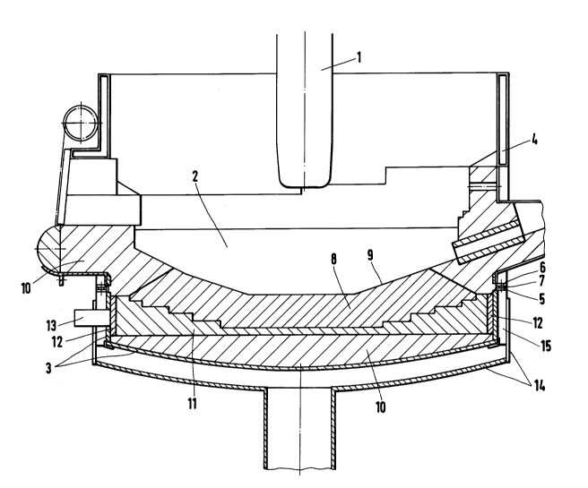
The invention is described in greater detail hereinafter
relative to an embodimen~ shown in the drawing, which is
a diag~ammat~c sectional representatlon of a d.c. arc
~urnace. In the centre of the f urnace is provided a vert-
ically extending cathode 1 adJustable in ~aid direction.
Between the cathode and the surface of a ~olten ~etal bath
2 flo~s an elec~ric current in the form of an arc. ~his
produces ~dequate heat to melt metal c~arged i.~to the fur-
nace and keep i~ in the molten state.
The furnace has a steel ~acket constituted by a lower part
3 and a cylindrical upper part 4. Lower par~ 3 and upper
part 4 are mechanically interconnected by ~langes 5,6 and
electriCally separated by an insulatlng ln'ermediate
layer 7.
The ~urnace lining contains a layer o~ elec~rically conduc-
ti~e, wear-resistant and refractory brlcks 8, ~hich are
in contact with the molten metal 2. The une~enn-
esse~ of the layer sur~ace facing the molten metal
cau~ed ~y the shape of the bricks 8 ls compensated by an
electrically conducti~e ramming mass 9. The layer of brick~
8 extends over mos~ of the bottom or hearth area of the
furnace. Electrically conductive, wear-resistant and ref-
ractory materials for produclng bricks 8 are kno~n, e.~.
in the form of carbon-magnesite bricks. The outer lining
layer comprises in the hearth area ~ric~s 10 made from
electrically insulating, refra~tory material. Between
the insulatin~ layer o~ brick~ 10 in the hearth a~ea and
the electrically conductive layer o~ bricks ~ ls provided
_ 4 _ 2D27~7~
a layer of bricks 11 having a higher electrical conductivity
than bricks 8, but not having the same wear resistance and
refractoriness as these. Graphite bricks are preferably used
as the bricks 11. The thickness of the layer of bricks 11
increases towards the outer edge. The drawing shows this layer
in ocntinuous form, but it can also be omitted in the central
hearth area. The graphite bricks should be placed to that the
radial direction of the furnace corresponds to the direction of
extrusion of the graphite so that electrical resistance is minimized
in the radial direction of brick layer 11. -~
On the inside of the cylindrical portion of lower part 3, a
copper ring 12 is plated or in other ways fixed to adjoin
the layer of bricks 11. Copper ring 12 can be continuous or
in its circumferential direction can be subdivided into several
segments. Copper conductors 13 are passed through the lower part
3 and connected to the copper ring 12 for power supply purposes.
The lining is formed by a continuous layer of refractory,
electrically insulating bricks 10 above copper ring 12 and
in the wall area of the furnace.
As a result of the large-area connection between copper
ring 12 and the good conducting layer of bricks 11 on the
one hand, as well as said layer and the conductive layer of
bricks 8 on the other, a large part of the inner surface of
the lining in contact with the molten metal 2 is largely at
the same potential. Correspondingly there is a distribution of
the current flow over virtually the entire surface of the
molten metal 2. This minimizes the occurrence of cold zones,
particularly in the vicinity of the furnace wall.
The hearth and the lower wall area of the furnace are provided
with means for guiding a cooling medium, preferably air. The
cooling medium is supplied below the centre of the hearth and
in a carvity delimited by a bottom plate 14 of the hearth is
brought radially outwards and by a deflection to the wall area
_ ~ 5 ~ 2027479
level with the copper ring 12. Cooling ri~s 15 projecting
radiallY outwards into the cayity from lower part 3 increiase
the coollng e~fect ~nd serve to carry the~cooling medium.
For a furnace wi~h a capacity of 6Q t and a diameter of
approximately 5.2 m, as well as a maximum current intensity
o~ 8~, 000 A, t~ p~er ring 12 e . 9 . h~s ;~ height o~ ~00_
700 mm and a thicknes~ o~ 20-60 mm.
If the ~tatics of the ~urnacP are ensure~ by a steel frame-
work and not a steel ~acketi as a function of the d.c. -~
arc furnace constr~ction, the copper ring can also be fixed
to the framework ln~tead of to the iacke~.