Note: Descriptions are shown in the official language in which they were submitted.
Arranqement for a vacuum cLeaner
The present invention relates to an arrangement for a vacuum cleaner
of the kind indicated in the preamble of appending claim 1.
From W0-87/01921 a vacuum cleaner is known which is provided with
a suction fan driven by an electric motor. The vacumm cleaner is
supplied from the mains and is provided with an electronic speed
control device by which the suction force of the vacuum cleaner can be
set. ~y actuation of an operating member the vacuum cleaner can be
driven at an increased power level, not allowed, during a predetor-
mined time period after which the vacuum cleaner motor is operated to
~ return to its normal power range. In addition, means are provided for
~ preventing the renewed operation in the region not allowed before the
;~ lapse of a predetermined time.
The device described in the publication, usually referred to as a
~booster~, has a design which is relatively complicated comprising
~15 quite a number of electronic components. Therefore, one object of the
~i invention is to provide a booster device performing the same function
~` but having a simpler design.
In addition, the booster device described in the publication
presupposes the vacuum cleaner to be operated from the mains. ~ -
; 20~ Nowadays, battery operated vacuum cleaners have been manufactured too
and it is a further object of the invention to provide a booster
device which can be used also in such application.
si~ The objects mentioned above will be achieved by an arrangement
~: `
having the characterizing features indicated in claim 1. Preferred
j25 embodi~ents have been included in the accompanying sub-claims.
., ~ .
'~' '' i
:
. : ~ i,
-- 2
The invention will now be described more in detail in connection
with two embodiments relating to a mains operated vacuum cleaner and
to a battery operated vacuum cleaner, respectively. The description is
made with reference to the enclosed drawings, in which:
Fig. 1, schematically, shows a vacuum cleaner,
Fig. 2 is a circuit diagram for a booster device in connection
with a mains operated vacuum cleaner;
Fig. 3 is a circuit diagram for a booster device ln connection
with a battery operated vacuum cleaner.
Fig. 1 shows, schematically, the construction of a vacuum
cleaner. In a housing 10 there are provided an inlet opening 11 and an
outlet opening 12. By a suction fan 14, driven by an electric motor
15, an air stream is created between the inlet and outlet openings via
a dust container 13. An electronic speed control device 16 is provided
lS by which the suction force can be set for different operating modes.
The setting takes place by means of a potentiometer 17 operated by a
knob 18. For the switching-in of an extra high suction force, the
: . .
booster position, a push-button 19 is provided, by means of which the
control de,vice is operated.
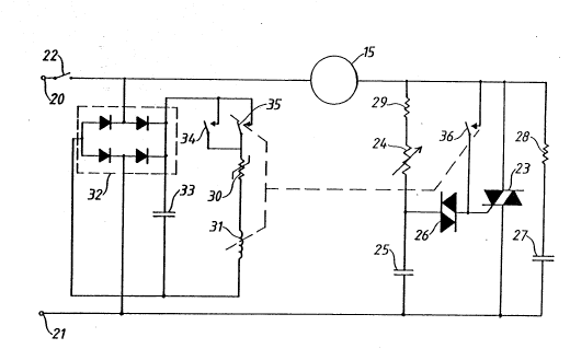
Fig. 2 shows a circuit diagram for a mains operated vacuum ;~
cleaner provided with a booster device according to the invention. The
.,: . .
motor, which is a common series motor, is connectable, via terminals
20,21 and a switch 22, to an AC mains, for example for 220 volts. The
motor is connected in series with a triac 23 which, in the usual way,
is provided with a trigger device comprising a resistor 29, a poten-
tiometer 24, a capacitor 25 and a diac 26. The potentiometer, the
resistor and the capacitor form a series circuit which is connected in
parallel with the triac 22. The connecting point between the poten-
tiometer and the capacitor is connected, via the diac 26, to the
:
control electrode of the triac 23. A series circuit, formed by a
capacitor 27 and a resistor 28, is connected in parallel across the
triac, protecting it against transients. ~y means of the potentiometer
24 the desired trigger angle for the triac 22 can be chosen and by
that the speed and the suction force can be varied.
The component values of the resistor 29, the potentiometer 24 and
the capacitor 25 have been chosen so that the triac is not conducting
through the whole of each half period even at the maximal suction
force, set by the potentiometer. This means that the maximal mean
voltage of the motor is lower than the mains voltage.
In order to provide the additional suction force the vacuum
cleaner is to be operated in the booste~ mode, here meaning that the
triac is conducting through the maximal dwell angle, causing the mean
voltage mainly to equal the mains voltage. The motor is rated to the
maximum mean voltage, set by the potentiometer 24, and must not
operate at mains voltage level longer than for a short period of 10-
20 seconds. In order to provide for the booster mode, referred to, a
special circuit arrangement is included comprising a PTC-resistor 30
in series with a relay 31. This series circuit is supplied with
current from the mains via a rectifier 32, a smoothing capacitor 33
and a sprlng-back contact 34, operated by the push-button 19 (Fig. 1).
Via a relay contact 35, connected in parallel with the contact 34,
self energising current is supplied to the relay. A further relay
contact 36 is connected in parallel to the series circuit consisting
of the diac 26 and the potentiometer 29.
~; The circuit of Fig. 2 functions in the following way. The mains
voltage is applied by closing of switch 22. ~y settlng of the poten-
tiometer 24, the suitable speed for the motor is chosen and thereby
the desired suction force with regard to the nature of the surface to
4 ~ V fJ ~
be vacuumed. If there is a desire for extra high power from the vacuum
cleaner, the contact 34 is closed causing current to flow through the
¦ winding of the relay 31. The relay becomes energised closing the hold
contact 35 by which the relay is supplied with current even after the
return of the contact 34 to the position shown in Fig. 2. The relay
closes the contact 36 too, disconnecting the trigger device,
comprising the potentiometer 24, the capacitor 25 and the diac 26.
Now, the trigger device receives trigger pulses directly from the
mains voltage, for each half period meaning that the triac will be
triggered already when the voltage between the control electrode and
the terminal 21 amounts to 1 volt or so, 3 volts at the most,
positively or negatively. Therefore, one could say that the mean
voltage (RMS) supplied to the motor mainly equals the mains voltage.
Accordingly, the said voltage exceeds the rated supply voltage of the
motor, determined by the trigger device 24-26. For that reason, as
mentioned above, the motor must not operate in the booster mode longer
than for a short time of 10-20 seconds, after which the motor have to
return to a speed within a speed range which, at a maximum, results in
the rated motor output.
The limit of time for the booster mode is determined by the PTC-
resistor 30 which when heated to a sufficient e~tent changes its
resistance abruptly from a low to a high value, causing the current
through the relay to drop below the hold value. The relay turns-off,
the icontacts 35 and 36 open and the motor speed is again determined by
the trigger clrcuit described.
An embodiment in connection with a battery operated vacuum
cleaner is shown in Fig. 3. The vacuum cleaner motor 15 is driven from
a lead accumulator 36, for 12 volts, via a switch 37. For operation in
the booster mode an additional battery 3~ ls provided, being a
:
J~
rechargeable battery of the NiCd-type. This battery can be connected
in series with the battery 36 to provide a higher supply voltage for
the motor, thereby increasing its speed and its suction force. In
order to connect the batteries in series a relay 39 is used which has
a change-over contact 40. When the relay is inactivated the contact 40
bears on a contact 41, thereby connecting the motor 15 to the positive
terminal of the batter~ 36. When the relay is energised, the contact
40 bears on a contact 42 which is connected to the positive terminal
of the battery 38. The negative terminal of the battery is connected
to a conductor 43 which is, via switch 37, connected to the positive
terminal of the battery 36.
Via a transistor 44, the relay 39 is connected to a conductor 45,
being a common current return conductor in the circuit diagram. Via a
transistor 47, a PTC-resistor 46 is connected to a condu~tor 48
IS connected to the contact 40. In addition, via two resistors 49,50, the
PTC-resistor is connected to the conductor 45. The resistors form a
voltage divider and the co M ecting point between the resistors is
connected ta the control electrode (the base) of the transistor 44.
The cantrol electrode (the base) of the transistor 47 is connected,
vla a resistor 51 and a diade 52, to the conductor 43. Via a spring-
returned, manually operable cantact 54 the connecting point between
the diode 52 and the resistor 51 is connectable to a capacitor 55, the
, ~ .
opposite end of which is connected to the conductor 45. In order to
prevent transients, a diode 56 is connected in parallel ta the relay
25 ~ 39. Far the same purpose a diade 57 is connected in parallel to the
matar 15.
The arrangement shown in Fig. 3 functians in the following way.
Upan clasing of the switch 37 current flows in the battery clrcuit via
the conductor 43, the contacts 41,40, the conductor 48, the motor 15
~ ~ .
~J ~ ~J'~
and the conductor 45. As a result, the motor rotates at a speed
determined by the voltage of the battery 36. Now, if it is desired to
operate the motor in the booster mode at increased voltage, contact 54
is actuated connecting the capacitor 55 into the control circuit of
transistor 47. The transistor is brought into its conductive state and
a current will flow in the control circuit of transistor 44. Also this
transistor is forced to conduct and a current will flow through the
winding of relay 39 causing the relay to become energised so that the
contact 40 is operated to engage the contact 42. Thereby, via the
conductors 48 and 45, the battery 3~ in series with the battery 36
will be connected to the motor which will be driven at an increased
speed determined by the added voltages from the batteries 36 and 38.
Via the circuit consisting of the diode 52 and the resistor 51
' the base of the transistor 47 is given a potential keeping the
transistor conducting even after the return of the contact 54 to the
position shown in the figure. Therefore, a current will continue to
flow in the control circuit of the transistor 44 and through the
PTC-resistor 46. The resistor is heated and after the lapse of lQ to
20 seconds a temperature has been reached at which the resistance is
abruptly changed from a low to a high value. This causes the
transistor 44 to be cut-off so that the current through the relay
winding ceases to flow and the relay turns off. The contact 40 changes
over to engage the contact 41 and the initial condition has been
reest!ablished.
The circuits described above may be modified for use of NTC-
, ~ ,
~ resistors Instead of PTC-resistors.
:~ :
~'