Note: Descriptions are shown in the official language in which they were submitted.
CA 02027~9~ 1997-06-18
2~7~
WO ~/1109~ PCT/US~/01182
STFRT~.~ PRODUCT AND METHOD FOR
STERILIZING AND ASS~MRT.TNG SUCH PRODUCT
BACRGROUND OF THE lNv~NllON
The present invention relates generally to
sterile products and to methods for sterilizing and
assembling such products. More particularly, the present
invention relates to sterile products and to methods for
sterilizing and assembling such products, wherein the
products have two or more portions which are mutually
incompatible with regard to the method of sterilization.
Pre-sterilized, disposable medical products are
commonplace in the United States and other countries
throughout the world. One heretofore significant
restraint on the design, development, and manufacture of
such products has been the fact that certain desirable
products would include portions or components which are
mutually incompatible from a sterilization standpoint.
lS For example, it may be desirable to provide a unitary,
pre-sterilized product which has a sealed liquid or
powder drug component and a plastic apparatus component,
such as a tubing or flow control set, for dispensing the
drug.
The integral product, however, cannot be
sterilized after assembly because not all of the
components may be subjected to the same form of
sterilization. For example, the plastic apparatus
component (e.g. the tubing or flow control device) may
only be sterilizable with radiation or gas. The drug
component, on the other hand, may not be sterilizable with
either gas or radiation -- gas sterilization would be
ineffective to sterilize a sealed drug, while exposing the
drug to radiation may lead to product degradation or
otherwise have a deleterious effect on the drug.
Accordingly, efforts have been made to devise
means for joining, in a sterile manner, components which
are individually pre-sterilized. One example of such a
product is the blood processing (apheresis) kit
manufactured and ~old by the Fenwal division of Baxter
CA 02027~9~ 1997-06-18
WO ~/11~ PCT/US~/01182
Healthcare Corporation of Deerfield, Illinois.
Typically, the blood processing kit (such as those
produced by Baxter Healthcare) consists of two or more
containers filled with medical solutions, connecting
tubes, and a flow control subassembly. The solution
containers may be filled with anticoagulant to prevent
blood clotting, dextrose as an energy source for blood
cells, saline, or other medical liquid utilized in the
treatment of the patient or in the collection of blood
components. A network of tubing connects the solution
containers and the flow control subassembly.
The current process for manufacturing such
apheresis kits involves a multi-step process of assembling
an entire apheresis kit with empty solution containers;
filling separate containers with the desired solution;
separately sterilizing the assembled kit (with the empty
containers) and the filled containers; transferring in a
sterile manner the pre-sterilized solution into the pre-
sterilized empty solution containers; and discarding the
original (now empty) solution containers.
The sterile transfer of solution is achieved
through the use of a sterile docking device such as the
device disclosed in U.S. Patent No. 4,157,723. The
sterile docking device shown there utilizes a pair of
mating halves, with facing membranes. One half of the
docking device is connected to the empty pre-sterilized
containers, and the other half is connected to the full
pre-sterilized container. After the halves are joined,
the docking device is exposed to radiant energy, causing
the membranes within the docking devices to melt and form
a sterile fluid pathway through the device. Once this
pathway is formed, the previously sterilized solution is
manually transferred from the original bag to the empty
bag attached to the kit. After transfer, the transfer
tubing is sealed and cut, and the emptied bags and the
docking devices are discarded.
While this process has generally worked
satisfactorily, it entails the step of transferring
CA 02027~9~ 1997-06-18
2~2i'75g~
WO90/11095 PCT/US90/01182
solution from one container to another in a sterile
manner and all the extra quality control procedures
associated with such a step. Also, once the solution is
transferred, the original solution bags and sterile
docking devices cannot be reused and must be discarded,
adding cost to the final product.
For these reasons, it is a general object of the
present invention to provide an improved sterile product
of the type described above and improved methods for
sterilizing and assembling such products.
This and other objects of the present invention
are set forth in the following detailed description of the
illustrated embodiment of the present invention.
CA 02027~9~ 1997-06-18
2~7 j9 j
WO ~/11095 PCT/US90/01182
SUMMARY OF THE lN V~. l-lON
The present invention is directed generally to
sterile integral products, to methods for assembling such
products, and to methods for sterilizing a selected
portion of such products. The sterile integral product
may consist of a first portion which is unsuited to
selected forms of sterilization, such as radiation, and a
second portion which is particularly well suited to
utilizing such selected forms of sterilization. In
accordance with one aspect of the present invention, the
second portion of the product may be exposed to the
selected form of sterilization, while the other portion of
the product is shielded from the selected form of
sterilization. This may be performed with the two
portions integrally connected and in relatively close
association with each other.
In another embodiment of the present invention
the first portion may be sterilized prior to joinder with
the second portion, in a manner which achieves a
sufficient degree of sterilization while not adversely
affecting it, such as steam heat. The second portion may
be sterilized prior or subsequent to joinder with the
first portion, utilizing a form of sterilization such as
gas or radiation, which is unsuitable for sterilizing the
first portion. The portions are joined by first isolating
a part of the first portion and attaching it to the second
portion. If the second portion is also sterilized prior
to joinder, then a part of the second portion is also
isolated. The isolated parts of the first and second
portions are then joined and the joined isolated portions,
or the isolated part of the first portion and all or some
of the second portion if the second portion is not pre-
sterilized, are then sterilized in one of the selected
manners, while the remainder of the first portion is
shielded from adverse effect by such selected form of
radiation.
The isolated parts of the first and second
product portions may include means defining a fluid flow
CA 02027~9~ 1997-06-18
202t75~
WO ~/1109~ PCT/US~/01182
conduit between the first and second product portions.
The fluid flow conduits may be isolated from the remainder
of the product portions by mechanical means such as
clamps, valves or the like, or by the inherent
characteristics of the conduit itself, which limits
possible ingress or movement of bacteria or organisms
toward the remainder of the product portion. In any
event, the isolated portions are subjected to one of the
selected forms of sterilization so as to assure sterility
of the isolated portions, while the remainder of the first
product portion is shielded to prevent adverse effects.
The isolating means may then be removed, if necessary, to
yield a connected integral sterile product, made up of
portions which are otherwise mutually incompatible from a
sterilization standpoint.
In accordance with a further aspect of the
present invention, the preferred selected form of
sterilization is irradiation by electron beam. An
electron beam may be easily focused on the isolated
portions, readily started and stopped. An electron beam
may also be readily shielded from any personnel involved
in product manufacture and/or from the remainder of the
product which should not be exposed to radiation.
The present invention has particular application
in the assembly and sterilization of medical products
containing medical liquids or drugs. For example, in one
version of the present invention, the first product
portion includes one or more sealed containers filled with
a medical liquid or drug which is adversely affected by
ethylene oxide gas and/or radiation sterilization. The
second product portion may comprise an administration
apparatus which is to be directly attached to the first
portion for administering the liquid or drug to a patient.
Such administration apparatus, however, is only
sterilizable in a manner which is incompatible with the
fluid or drug, such as radiation or ethylene oxide gas.
In accordance with the present invention, the
first portion is separately sterilized by autoclaving,
CA 02027~9~ 1997-06-18
2027595
i.e., steam heating, the container and contents, while the second
portion may be separately sterilized by either gas or radiation.
Once the product portions have been separately sterilized, the
product is assembled.
In one arrangement, each portion of the product includes
means defining a flow path, e.g., plastic tubing, in communication
with its respective product portion. In accordance with the
present invention, the entire product is assembled by isolating at
least a portion of the flow paths from the remainder of the
product portions and joining the isolated sections of the flow
path together. The flow path may be isolated by clamping the flow
paths associated with the first and second product portions or,
alternatively, by providing a normally-closed frangible connector
in the flow path of each portion. If the flow paths have a
sufficiently small bore, there may also be isolation by the
inherent resistance to flow within the inside of a tube, thus
eliminating the need for separate clamping or blockage of the flow
path.
After joinder, the isolated fluid flow path is sterilized by
exposing it to an electron beam. During exposure of the flow path
to the electron beam, the remainder of the first product portion
is shielded from the beam in order to protect the medical fluid or
drug within the container from any adverse effects of radiation.
Other aspects of the invention are as follows:
A method for sterilizing a selected portion of a product
comprising: exposing said selected portion of said product to an
electron beam to effect sterilization of said portion; and
shielding at least a portion of the remainder of said product from
the radiation of said electron beam.
A method for sterilizing an integral product having a
first portion which is substantially adversely affected by
exposure to a selected form of sterilization and a second portion
which is not adversely affected by such form of sterilization,
said method including the steps of: sterilizing said first
A ' ~
CA 02027~9~ 1997-06-18
2027595
6a
portion without substantially adversely affecting said first
portion; exposing said second portion to said selected form of
sterilization while said first portion is in relatively close
association with said second portion; and shielding said first
portion from said selected form of sterilization.
A method for sterilizing an integral product having a first
portion and a second portion, each portion having means defining a
flow path communicating with said respective portion, said flow
path defining means being joined to provide a flow path between
said first and second portions, said method including the steps
of: sterilizing said first portion prior to joinder to said
second portion; sterilizing said second portion prior to joinder
to said first portion; isolating said flow path defining means
from the respective remainder of each of said portions prior to
joinder; sterilizing said flow path defining means after joinder;
shielding selected of said first and second portions from the
effect of the sterilizing of said flow path defining means during
said sterilizing.
A method for assembling a sterile product having at least
two parts, comprising: sterilizing the first part of said product;
isolating a selected portion from the remainder of said first
part; attaching a second part of said product to said selected
portion; exposing said selected portion to an electron beam
sufficient to effect sterilization of said portion; and shielding
the remainder of said first part from the radiation of said
electron beam.
A method of assembling a sterile integral product having a
first portion which is substantially adversely affected by
exposure to a selected form of sterilization and a second portion
which is not adversely affected by such form of sterilization,
said method including the steps of: sterilizing said first portion
prior to joinder to said second portion without substantially
adversely affecting said first portion; isolating a selected area
of said first product portion; joining said second product portion
~. A, ~
IA
CA 02027~9~ 1997-06-18
2027595
6b
to said first product portion at said selected area; exposing at
least said selected area to said selected form of sterilization
while said first product portion is in relative close association
with said second portion; and shielding said first portion from
said selected form of sterilization.
A method for assembling a sterile integral product having a
first portion and a second portion, each portion having means
defining a flow path communicating with said respective portion,
said flow path defining means being joined to provide a flow path
between said first and second portion, said method including the
steps of: sterilizing said first portion prior to joinder
to said second portion; sterilizing said second portion prior to
joinder to said first portion; isolating said flow path defining
means from the respective remainder of each of said portions prior
to joinder; joining said flow path defining means subsequent to
isolation to provide a flow path between said first and second
portions; sterilizing said flow path defining means after
joinder; and shielding selected of said first and second portions
form the effect of the sterilizing of said flow path defining
means during said sterilizing.
A method for assembling a sterile integral product
comprising: providing a first product portion including plastic
container with contents therein and a fluid flow conduit extending
therefrom; providing a second product portion including a fluid
flow conduit; sterilizing said first product portion without
materially adversely affecting the container contents; sterilizing
the second product portion in a manner which would adversely
affect the container contents; joining the end portions of said
fluid flow conduits to provide for communication between said
first and second product portions; the fluid flow conduits to an
electron beam a sufficient time to sterilize the end portions; and
shielding the first product portion from the electron beam during
sterilization of said conduit end portions.
A~
CA 02027~9~ 1997-06-18
2027595
6c
A product having a selected sterile portion produced by;
exposing said selected portion of said product to an electron beam
to effect sterilization of said portion; and shielding at least a
portion of the remainder of said product from the radiation of
said electron beam.
A product having a first portion which is substantially
adversely affected by exposure to a selected form of sterilization
and a second portion which is not adversely affected by, such form
of sterilization, which product is produced by: sterilizing said
first portion without substantially adversely affecting said first
portion; exposing said second portion to said selected form of
sterilization while said first portion is in relatively close
association with said second portion; and shielding said first
portion from said selected form of sterilization.
An integral product having a first portion and a second
portion, each portion having means defining a flow path
communicating with said respective portion, said flow path
defining means being joined to provide a flow path between said
first and second portions, said product being produced by:
sterilizing said first portion prior to joinder to said second
portion; sterilizing said second portion prior to joinder to said
first portion; isolating said flow path defining means from the
respective remainder of each of said portions prior to joinder;
joining said flow path defining means; sterilizing said flow path
defining means after joinder; shielding selected of said first and
second portions from the effect of the sterilizing of said flow
path defining means during said sterilizing.
A product produced by: sterilizing a first portion of said
product; isolating a selected portion from the remainder of said
first product portion: attaching a second portion of said product
to said selected portion; exposing said selected part of said
product to an electron beam sufficient to effect sterilization of
said portion; and shielding at least a portion of the remainder of
said first product portion from the radiation of said electron
beam.
CA 02027~9~ 1997-06-18
2027595
6d
A sterile integral product having a first portion which is
substantially adversely affected by exposure to a selected form of
sterilization and a second portion which is not adversely affected
by such form of sterilization, which product is produced by:
sterilizing said first portion prior to joinder to said second
portion without substantially adversely affecting said first
portion; isolating a selected area of said first product
portion; joining said second product portion to said first product
portion at said selected area; exposing at least said selected
area to said selected form of sterilization while said first
product portion is in relatively close association with said
second portion; and shielding said first portion from said
selected form of sterilization.
A sterile integral product having a first portion and a
second portion, each portion having means defining a flow path
communicating with said respective portion, said flow path
defining means being joined to provide a flow path between said
first and second portion, said product produced by: sterilizing
said first portion prior to joinder to said second portion;
sterilizing said second portion prior to joinder to said first
portion; isolating said flow path defining means from the
respective remainder of each of said portions prior to joinder;
joining said flow path defining means subsequent to isolation to
provide a flow path between said first and second portions;
sterilizing said flow path defining means after joinder; shielding
selected of said first and second portions form the effect of the
sterilizing of said flow path defining means during said
sterilizing.
A sterile integral product produced by: providing at first
product portion including at plastic container with contents
therein and a fluid flow conduit extending therefrom; providing a
second product portion including a fluid flow conduit; and
CA 02027~9~ 1997-06-18
2027595
6e
sterilizing said first product portion without materially
adversely affecting the container contents; sterilizing the second
product portion in a manner would adversely affect the container
contents; joining the end portions of said fluid flow conduits to
provide for communication between said first and second product
portions; the fluid flow conduits to an electron beam a sufficient
time to sterilize the end portions; shielding the first product
portion from the electron beam during sterilization of said
conduit end portions.
Further features of the present invention will become
more fully apparent in the following description of the
illustrated embodiments and from the appended claims.
CA 02027~9~ 1997-06-18
C~2~7~g~
WO ~/110~ PCT/US90/01182
DETATT~n DESCRIPTION OF THE DRAWINGS
Figure l is a vertical plan view of a sterile
product embodying the present invention and assembled and
sterilized in accordance with the method of the present
invention.
Figure 2 is an enlarged cross-sectional view of
the connected conduits which form a portion of the product
of Figure l.
Figure 3 is a cross-sectional view taken along
line 3-3 of Figure 2.
Figure 4 is a plan view of two containers of
medical liquid or the like which comprise a portion of the
product depicted in Figure l.
Figure 5 is a plan view, partially removed, of
liquid administration and processing apparatus which forms
another portion of the product depicted in Figure l.
Figure 6 is a plan view of a fixture, with
portions of the product of Figure l mounted on the fixture
in the position for sterilization on isolated portion of
the product.
Figure 7 is a diagrammatic plan view of the
fixture and product portions of Figure 6, depicting the
sterilization of the isolated portions by irradiation.
Figure 8 is a sectional view of apparatus which
may be employed in carrying out the sterilization method
of the present invention.
Figure 9 is a sectional view of alternative
apparatus for performing the sterilization of the product
portions depicted diagrammatically in Figure 7.
Figure l0 is a top view of a fixture for use with
the apparatus depicted in Figure 9 for carrying out the
present invention.
Figure ll is a side view of the fixture of Figure
l0 taken along line ll-ll of Figure l0, and depicting a
medical fluid container in phantom.
Figure 12 is a plan view of a slide clamp which
may be used in the practice of the present invention.
CA 02027~9~ 1997-06-18
2 0 ~
WO ~/110~ PCT/US~/01182
Figure 13 is an enlarged plan view of the
gripping area of the clamp of Figure 12 taken at the area
designated 13 in Figure 12.
Figure 14 is a cross-sectional view of the clamp
of Figure 12, taken along line 14-14.
Figure 15 is a partial cross-sectional view of
the clamp of Figure 12, depicting the sealing action when
applied to flexible plastic tubing.
The present invention is generally embodied in a
product 10, and in the methods of sterilizing and
assembling such product, which product includes one or
more medical liquid containers 12 and liquid
administration or processing apparatus 14. In accordance
with the present invention, one product portion, the
containers of medical liquid may not be radiation
sterilized because of deleterious product effects, and may
not be gas sterilized because they are sealed containers.
As a result, the most effective sterilization for such
medical li~uids is autoclaving. The other product portion
14 comprises apparatus for administering or processing the
liquid contained in the containers 12. That product
portion, however, is not effectively sterilized by
autoclaving, but must be radiation sterilized or
sterilized using ethylene oxide gas.
The product, in Figure 1, which is depicted for
purposes of illustration only and not for limitation, is a
closed apheresis kit or circuit, which may be used, for
example, with the CS-3000 Blood Cell Separator marketed by
Baxter Healthcare Corporation of Deerfield, Illinois. A
typical apheresis set is shown in more detail, for
example, in U.S. Patent No. 4,410,026 to Boggs. In this
particular product, container 12a is a flexible plastic
bag containing a medical fluid, such as a parenteral
solution or, more particularly, a 0.9 percent sodium
chloride solution for use in the apheresis process.
Container 12b is also preferably a flexible plastic bag.
It may contain, for example, a blood preservative, such as
anticoagulant citrate dextrose.
CA 02027~9~ 1997-06-18
2~7~9~
PCT/US~/0l182
WO ~/1109~
The bags of liguid are attached to the liquid
administration or processing apparatus 14 through outlet
ports 16 disposed at the end of the bag and in
communication between the interior of the bag and drip
chambers 18, which may be used for monitoring the flow
rate of solution from the bags. Flexible plastic tubing
segments 20a, b and c, respectively, extend from the
bottoms of the drip chambers for attachment to the liquid
administration and processing apparatus 14.
The liquid administration and processing
apparatus 14 comprises a rigid, plastic panel 22 which
mounts flow control valves such as 24 and looped tubing
portions 26 for cooperation with rotary peristaltic pumps,
which are provided on the CS-3000 Blood Cell Separator
manufactured and sold by Baxter Healthcare Corporation.
The housing 22 also mounts the fluid circuitry for
controlling the flow of liquid in the overall system in
cooperation with the CS-3000 Blood Cell Separator. The
details of this housing and fluid circuitry system are
depicted in more detail in issued public patents, such as
U.S. Patent No. 4,410,026, referred to above. To that
extent, the '026 patent is incorporated by reference
herein.
The tubing segments 2Oa, b, and c which extend
from the drip chambers of the medical liquid containers
are joined to mating tubing segments 28a, b and c of the
liquid administration or processing apparatus 14 in the
manner depicted more clearly in Figures 2 and 3. As shown
in Figure 2, tubings 20a and 28a are joined in fluid
communication by a surmounting flexible plastic sleeve 30.
The end of each tubing segment 20a and 28a is inserted
into the end of the flexible plastic sleeve 30 and sealed,
such as by heat, sonic or solvent bonding therewithin.
Solvent bonding, with a solvent such as with
cyclohexanone, is simple and is presently the preferred
method for joining the tubing segments in a sealed manner.
Figure 3 depicts the joint of Figure 2 in cross-
section, taken along line 3-3 of Figure 2. It shows the
CA 02027~9~ 1997-06-18
20~i7~9~
WO ~/11~5 PCT/US~/01182
tubing segment 20a contained within and sealed to the
interior surface of the flexible sleeve 30. This drawing
will be referred to later in discussing the sterilization
that takes place in accordance with the method of the
present invention.
Figures 4 and 5 depict the medical liquid
containers 12 and the liquid administration or processing
apparatus 14, respectively, as they appear prior to
joinder. More particularly, Figure 4 depicts the
containers 12a and 12b as they would appear at the time of
their sterilization. As described briefly earlier,
because containers 12a and 12b are sealed, gas
sterilization, such as the use of ethylene oxide, may be
unavailable, depending on whether the bag is gas
permeable, for sterilizing these products. Moreover,
radiation sterilization is not preferred because of
possible deleterious effects on the product contents which
results from the radiation. Accordingly, the containers
12a and 12b are preferably autoclaved, via steam heat, to
achieve or exceed the appropriate sterility level required
by the United States Food and Drug Administration.
In contrast to the liquid containers 12, the
liquid administration and processing apparatus 14 is
preferably sterilized with radiation or gas. Because of
the complex tubing circuitry and the nature of the
materials and construction of the liquid administration
and processing apparatus, autoclaving is not a preferred
sterilization technique for the apparatus 14.
Accordingly, the liquid containers 12 and the liquid
administration and processing apparatus 14 are preferably
sterilized separately, by the particular method of
sterilization which is best suited for that product
portion.
In accordance with the present invention, these
product portions, i.e., the liquid containers 12 and the
liquid administration and processing apparatus 14, are
preferably joined in a manner which does not require
resterilization or sterilization of the entire combined
CA 02027~9~ 1997-06-18
2~2~59a
WO ~/11~ PCT/US90/01182
11
product. Such, of course, would be impractical because
the product portions, that is the medical liquid
containers 12 and the liquid administration and
processing apparatus 14, are mutually incompatible
insofar as the sterilization method is concerned.
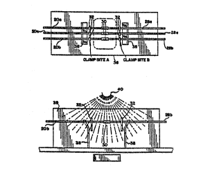
As diagrammatically illustrated in Figures 6 and
7, the product portions are joined by first isolating a
terminal end portion of the tubing segments 20a-c and 28a-
c from the remainder of the particular product portion.
For example, the terminal end of tubing 20a is isolated
from the remainder of the tubing and the associated drip
chamber. "Isolation" means blockage of the tubings from
ingress by bacteria or other airborne microorganisms. In
the preferred embodiment, the terminal end portions of the
tubings 20a and 28a are isolated from the remainder of the
tubing and the product portions by removable plastic,
radiation permeable slide clamps 32. Alternatively, the
end portions may be isolated by internal frangible
closures, such as those depicted in U.S. Patents Nos.
4,181,140 and 4,294,247. Such frangible closures would
normally seal the tubing, and would be open only after
joinder and sterilization of the joined, isolated regions
were complete. Regardless of whether slide clamp,
internal frangible closures or other means are used for
isolating the terminal end portions of the tubing,
preferably the material used for such clamps or closures
would be as nearly radiation transparent as possible to
assure that the terminal end portions, in their entirety,
including any portions contained within the clamps
themselves, would be sterilizable by radiation in general,
and electron beam radiation in particular.
The presently preferred slide clamp 32 is
depicted in more detail in Figures 12 through 14.- The
depicted slide clamp has previously been sold by the
Fenwal Division of Baxter Healthcare Corporation, under
product code no. 4R4423, for use in the collection and
laboratory processing of blood and blood components. The
slide clamp acts as a flow occlusion device, similar to a
CA 02027~9~ 1997-06-18
2~t75~
WO ~/11095 PCT/US~/01182
12
hemostat. By placing the clamp on the outside of the
tubing, the interior walls of the tubing are compressed,
thereby occluding flow while theoretically maintaining
sterility of the fluid path beyond the slide clamp (as
shown, e.g., in Figure 15).
In the present application, the slide clamp is
utilized for clamping the tubing segments 20a-c and 28a-c,
tubing which preferably has an inside diameter of 0.095
+/- 0.003 inches (approximately 0.241 +/- 0.0076
centimeters) and an outside diameter of 0.146 +/- 0.002
inches (approximately 0.37 +/- 0.005 centimeters). The
portion of the slide clamp for clamping the tubing,
depicted enlarged in Figure 13, preferably has a gap
opening of 0.026 inches (approximately 0.066 centimeters)
with a tolerance of + 0.005 and - 0.004 inches
(approximately + 0.0127 and - 0.0102 centimeters).
When tubing with the above-identified dimensions
is placed in the clamping or gripping portion of the
clamp, the tubing is tightly gripped and sealed with a
compressive force which is believed to be approximately
175 pounds per square inch (approximately 1206578.321
N/m )- Figure 15 depicts the gripping action in more
detail, with the area depicted by numeral 33, being a
representation of the compressed portion of the tubing
wall, being compressed by the clamp jaws 35.
Before describing the actual steps involved in
sterilization, however, there is one further alternative
for isolating the terminal end portions of the tubing
segments. Under normal assembly conditions, particularly
those associated with clean room environments,
microorganism ingress into open tubing would occur only in
the terminal end portion, and the remainder of the tube
and the product portion would remain sterile by reason of
the static condition of air within the tube and the
inherent resistance to flow of microorganisms into the
tube through the open terminal end. Thus, under these
conditions, a positive barrier may not even be required to
prevent contamination of the remainder of the product.
CA 02027~9~ 1997-06-18
202~759~
WO ~/1109~ PCT/US~/01182
13
However, slide clamps, internal frangible closures and the
like have the advantage of providing a positive barrier to
ingress of bacteria or microorganisms and are preferred at
the present time.
In accordance with the present invention, the end
segments of the tubings 20a-c and 28a-c are isolated by
slide clamps 32 prior to joinder. The sterile end covers
34 (Figures 4 and 5) of each tubing segment are then
removed and the ends of the tube are inserted into the
flexible plastic sleeve 30 and solvent sealed
therewithin. Following that step, the tubing is
preferably mounted on a fixture 36, such as that generally
shown in Figure 6. As may be seen there, the tubing is
held in place by a pair of tubing retainers 38, with the
tubing sleeve 30 and slide clamps 32 positioned between
the retainers.
The fixture 36, with the tubing segments
positioned thereon, is then exposed to a radiation source
40, as is figuratively shown in Figure 7. The radiation
source 40 is preferably an electron beam. During the
radiation of the isolated tubing end portions, the
remainder of the products, and in particular the medical
liquid containers 12 are shielded from the radiation
effects of the electron beam by an aluminum wall 39 or the
like, while they remain connected to the liquid
administration and processing apparatus 14.
Electron beam radiation is particularly
advantageous in this application. Electron beams are
unidirectional and may be relatively narrowly focused.
Also they may be readily turned on and off -- unlike gamma
radiation sources, which of course decay continuously
whether or not actually being used for product
sterilization. Further, radiation from the electron beam
may be readily shielded from other portions of the product
and from personnel involved in connection with the
manufacture of the product.
An accelerator such as a linear accelerator is
used to generate the electron beam. Various studies have
CA 02027~9~ 1997-06-18
2~2~ 9~
WO ~/1109~ PCT/US~/01182
14
been completed to determine the appropriate power and
radiation requirements to achieve sterilization,
particularly at the juncture of the tubing segments and
sleeve 30, where there is a double wall thickness, as
shown in Figure 3.
Initial studies were conducted using a 0.6 MeV
pulsed power electron beam instrument manufactured by
Pulse Sciences, Inc. Connection tubings were fabricated
from radiation grade polyvinylchloride plastic of size
typical for medical fluid administration apparatus, such
as set forth above. Far West Technology (FWT) dosimeters
(FWT-60-00, batch 6FM) and a FWT Radiachromic Reader were
used to quantify radiation dose.
Radiation-resistant spores of Bacillus pumilus
were utilized as a biological indicator. The D-value of
this organism is 0.15 Mrad as determined by Cobalt 60
irradiation of paper strips. The spore suspensions were
prepared by North American Science Associates, Inc.,
Northwood, Ohio. For the dosing studies, intact,
previously sterilized tubings were placed in an isolation
fixture and clamped. Ten microliters (approximately lo6
spores) of the suspension of test organisms were placed in
the interior of the tubing at a fixed site. Each tubing
was then cut at that site and subsequently rejoined using
a larger diameter tubing sleeve and joined together using
cyclohexanone. In some instances, approximately l06
spores were placed inside of each cut tubing half at the
location of the clamps (refer to Figure 6) prior to tubing
reconnection. The tubing was then allowed to remain in
the fixture of a minimum of twenty-four hours (in the
actual manufacturing process the units will be sterilized
immediately after the connection is made) after which the
fixture and tubing were exposed to varying doses of
irradiation from a 0.6 MeV electron beam accelerator. A
Faraday cup was used to measure the dose delivered to the
outside of the tubing and film dosimeters (FWT) were used
to quantify doses at various locations within the tubing.
Following irradiation, the inoculated tubings were
CA 02027~9~ 1997-06-18
2~iiS~
WO ~/11~5 PCT/US~/01182
aseptically removed from the pouches and the inoculated
areas individually transferred to lO ml of sterile water.
After sonification for ten minutes, serial dilutions were
made and samples were cultured at 30-35 C on tryptic soy
agar plates. Inoculated but non-irradiated tubings were
used as positive controls.
Results are shown in Table l. Completed
bacterial inactivation was seen at the distal (clamp
region) tubing inoculation sites following 2.2 Mrads of
radiant energy, however, this dose was insufficient to
achieve sterilization at the tubing center, due to reduced
electron penetration of the double wall thickness tubing
(sleeve) at the site of connection. These studies thus
indicated that a higher energy electron beam would be
required for effective sterilization.
A second series of studies was performed to
evaluate different beam energies/doses. A Pulserad 122A
linear electron beam accelerator rated at l.8 MeV was used
for these studies; energy levels of l.l, 0.9 and 0.75 MeV
were evaluated.
To study the variation of beam intensity at
various locations within the isolation fixture, dosimeters
were placed at the following locations: center of beam, l
l/2 inches (approximately 3.81 centimeters) above center,
l l/2 inches (approximately 3.81 centimeters) beneath
center, within the single walled tubing and within the
double walled "sleeve" area of the connection.
Approximately 0.5 Mrad was delivered to the tubing
contained within the fixture in each of two separate
experiments. As shown in Table 2, approximately one-half
of the dose delivered to the outside center of the tube
was available at the interior of the double walled
connection area (= 0.31 Mrad). About a 50~ falloff in
dose also occurred from the beam center to beam
periphery. The delivered radiation dose of the beam is
gaussian with intensity at the periphery being
approximately 50% of the intensity at the center. Since a
higher dose is required in the center double wall (sleeve)
-
CA 02027~9~ 1997-06-18
2021~9~
WO ~/1109~ PCT/US~/01182
16
area due to material thickness, the observed pattern of
energy delivery seemed well suited for the application.
Additional studies were performed using B.
pumilus pores as a biological indicator. For each dose
study, three tubings were placed in the isolation fixture
and positioned as would be the case during apheresis kit
manufacture. Two tubings were used for inoculation
studies while dosimeters were placed within the double-
walled central tubing area (junction site) and within the
tubing lumen at the clamp occlusion site of the third. A
dosimeter was also placed in a paper envelope and attached
to a Faraday cup.
Approximately 6.2 x 10⁵ B. pumilus spores were
placed at the intended site of reconnection under the
double-wall portion of tubing. An additional 8-9 x 10⁵ B.
pumilus spores were placed within the interior of each
tubing at the points at which it was clamped. After the
connection had been made, the tubings and fixture were
irradiated using a beam energy of 1.1 MeV. Additional
studies were performed using different tubings, inocula
and dosimeters; the delivered (exterior) dose in these
studies ranged from 0.45 to 6.00 Mrads.
Table 3 shows that while viable biological
indicator organisms were recovered when the tubings were
exposed to a low dose at an energy of 1.1 MeV irradiation
(external dose = 0.45 and 1.05 Mrads, respectively), no
organisms were recovered from the inoculated sites
following external doses of 2.38 Mrads or more. Culture
of non-irradiated control samples showed recoveries of
from 6 to 9 x 10⁵ viable organisms. Table 3 shows
bacterial recovery following various doses of electron
beam irradiation. Since the D value for B ~umilus is 0.15
Mrad, a total dose of 0.15 x 6 = 0.9 Mrad would be
anticipated to be needed for a 6-log reduction of viable
organisms. The third incremental dose delivered (1.35
Mrads inside the double wall connection area) exceeded the
anticipated (0.9 Mrads) dose required for 6-log organism
reduction. Thus, with an external dose of 2.38 Mrads and
- - -
CA 02027~9~ 1997-06-18
2~7~9~
WO ~/1109~ PCT/US~/01182
17
a delivered (worst case) internal dose of l.35 Mrads, a
spore log reduction of 9 was seen within the fluid-contact
pathway. Based on anticipated product and manufacturing
facility bioburden data, a sterility assurance level of in
excess of lO-l6 may be anticipated.
Additional dose/biological indicator studies
using 0.9 MeV and 0.75 MeV beam energies were also
conducted in a similar manner. At both beam energies, no
viable organisms remained following delivery of 2.5 or
more megarads of energy (Table 4).
While the above demonstrates the effectiveness of
beam energies as low as 0.75 MeV with 2.5 or more
megarads of delivered energy, preferably a 2.0 MeV linear
electron beam acceleration will be used in actual
production.
Calculations also demonstrated that a lO mm thick
aluminum sheet would be expected to be adequate to shield
products from 4.5 MeV electrons. This shield thickness is
expected to be adequate at both 2.5 and 5.0 Mrad doses.
Subseguently, specific dosimetry and biological
indicator studies were performed to quantify the radiation
dose delivered to portions of the apheresis kit and
solutions external to the isolation fixture/tubing target
area. In these studies, dosimeters and B. Pumilus
biological indicator strips were placed on the solution
containers. The connected tubing region and the shielded
isolation fixture were then subjected to 2.5 Mrad or 5.0
Mrad doses of electron beam irradiation as would take
place during the manufacturing technique. No radiation
was found to be delivered to the solution containers at
either dose of incident radiation (lower limit of
dosimeter detection = 0.05 Mrad). No significant
differences were seen in org~niC~ recovery between- non-
irradiated and shielded/irradiated biological indicator
strips, further indicating the adequacy of solution
fixture shielding using lO mm aluminum.
Based upon the above, solution stability/dating
is unlikely to be adversely affected by this change in the
CA 02027~9~ 1997-06-18
2~i755~
WO ~/1109~ PCT/US~/01182
18
apheresis kit manufacturing process. Assay of non-
irradiated control and shielded/irradiated solutions
exposed to 2.5 and 5.0 Mrad doses of radiation did not
show significant changes in solution constituents as
shown in Table 5.
Apparatus for carrying out the present invention
is depicted in Figures 8 through 11. Figure 8 shows an
electron sterilization unit having a radiation source 40,
radiation shielded housing 42 and a conveyor 44 for
loading and unloading the fixture 36 within the radiation
shielded housing 42. As depicted there, the fixture 36 is
mounted atop a carrier 46 adapted to move along the top of
the roller conveyor 44. The product 10, which comprises
the medical liquid containers 12 and liquid administration
or processing apparatus 14 lies atop the carrier. The
tubings 20a-c and 28a-c are fixed in the isolation
fixture 36 in the position indicated in Figure 6.
After the carrier 46 enters the housing 42, it is
raised by a piston cylinder arrangement 48 into the
position indicated in dashed lines in Figure 8. The walls
of the isolation fixture 36 surround the electron beam
emitter and isolate the remaining portions of the product,
particularly the medical liquid containers 12, from the
radiation resulting from the electron beam. After the
carrier is raised to the position shown in dashed lines,
the electron beam is turned on to provide the appropriate
radiation dose, as discussed in detail above and shown in
the preceding tables, to assure sterility of the tubing
area between the isolating clamps. Following
sterilization, the carrier is lowered and removed from the
housing along the roller conveyor 44.
Figure 9 depicts an alternative embodiment of
apparatus which may be used for carrying out the present
invention, which does not require as much shielding as the
apparatus of Figure 8, and is believed to be more
efficient in its operation. The apparatus depicted in
Figure 9 includes a shielded housing 50, a conveyor 52
upon which product carrier plates 54 move and a shielded
CA 02027~9~ 1997-06-18
~7!~
WO ~/11~5 PCT/US~/01182
19
closure member 56 mounted for vertical movement by an air
or hydraulic cylinder 58.
The detailed construction of the product carrier
plate is best seen in Figures 10 and 11. The carrier
plate has a generally rectangular, flat surface 58 upon
which the medical liquid containers 12 and the liquid
administration apparatus 14 rest. The tubings 2Oa-c and
28a-c lie along an outwardly extending and arcuate arm 60
with the flexible plastic sleeves 30 disposed at the end
of the arm over a U-shaped aperture.
After the product is placed upon the carrier and
the tubing arranged in the manner depicted in Figures 10
and 11, the carrier is moved into the position shown in
Figure 9 relative to the shielded housing. The lower
closure member 56 is then moved upwardly, nesting tightly
against and on the underside of the arm 60. As can be
seen from Figure 9, the end portion of the arm, where the
joining flexible plastic sleeves 30 are located is
positioned at a lower aperture 62 of the shielded housing
which is the focus of the electron beam. The beam is then
energized, as described above, to effect sterilization of
the isolated portion of the tubings 20a-c and 28a-c. The
closure member 56 is then lowered and the carrier removed
from the housing along the conveyor 52. The next carrier
is then moved into place and these steps are repeated.
The apparatus disclosed in Figures 9 through 11
requires less shielding than that depicted in Figure 8
due, in part, to the arcuate arm 60 (best seen in Figure
ll). The arcuate nature of the arm 60 creates a non-
linear serpentine path which greatly restricts theemission of any radiation from the isolated tubing area.
Although the present invention has been described
in terms of the preferred embodiment and utilizing a
specific product as an example of how it may be employed,
the present invention is not limited to the particular
product depicted in Figure 1 or to the apparatus shown in
the other drawings. The scope of the present invention is
defined by the appended claims.
CA 02027595 1997-06-18
2~'759a
WO 90/11095 PCr/US90/01182
o ~ ~
- c~ o o o o rn
,5 a ~D
Z X X
C
1-~; Z e~
U~ ~ ~
H O
O O O O O
~ P~ a
a z x x x ~:5
Z 1~ ID
.,~
o
~ e
V~ H ~ ~~
He O O O O O
e H ~1 ~
X X X X
O ~ I ~ D
_l
~a )
Z
C ~
-I 1' ~ U~ D
O ~ In O .
Z
Z
O HO n
i~ rn
5al~a ~ F
a c
~ ~ p u~ o o o rn
U
H ~
~ ~4 ~ N ~7
E~ r~
p U~
o Q ~5 ~ ~ ~ o
-- ~j h Sl Ll
U H ~ ~ ~ X
~ ~ ~ o o o o ~r
Ez ~-- o u~ ~ ~
1~ 3 ~1 ~I N ~ 11
U U~ A
CA 02027595 1997-06-18
2~2~7~9 j
WO90/1109~ PCT/US90~01182
21
TABLE 2
DELlv~K~D DOSE (Mrad)
DOSIMETER POSITION STUDY A STUDY B
Outside Center .55 .50
Outside Top .3l .3l
Outside Bottom .31 .31
Within Double Wall .31 .22*
Within Single Wall - .27*
*Tubing center was l/2 inch (l.27 centimeters) off
beam center.
CA 02027595 1997-06-18
5 ~ ~
WO 90/1109~ PCI/US90/01182
22
I
o ~ o
O U~ ~D ~ O ~D I I I I I I
Z ~ ~ ~ ~ ~ o
- -- X
~: ~ - o o o o o oo o o
o: ~Ln 0 o o o o oo
p~ ~ , . . . . . .. . C:i
E
O O ~)
X X O O O O OO
U N 0
O O
Z ~ X X o o o o oo ln
Z ~ Ur~ ~D X
O ~ ~1
U ~ O O N
X X c~
Z O O O O O O OO
U ~I ~ ..
H
E~ C
Z ~ I E
H O O t~;
~j X X O O O O OO CJ
H U ~
O O O
H ~1P~
Z ~; X X O O O O OO
H .5 0 0
U ~ ~ O
~ O O X
L ~
~ O~S~ O O O O OO N
U ~ _~
. . .
a ~ o u~ ~ o O
H ~ N 10 ~7~D r
Z 8 3 --I ~/~1 t~ ~ ~
U~
'i
U~ -1 ~~ In 0ul o ~ o o J
a~n ~ ~ o ~ Ou~ ~ ~ O
E~ o~1 ~ ~ ~ ~ ~ ~ ~
CA 02027595 1997-06-18
WO 90/1109~ PCI/US90/01182
z z
1 H
~n a ~ ~n a a~
Q H ~ O ~ ~
Z o~~o\~o\~ Z o\~ o\O o\O
-. H ~ _~_I O ~ i ~ ~ O c~
z 3
n ~3 ~ n
o -~
~h~ .~ ~ ~
Q Q
~z z
O N _I O
U h O _ U L~
z ~ o o Q~ ~ z ~ co o o
C X ~ O ~
~ ~ ~ U ~ g ~ U
O ~ ~
Z O
~ o
o o ~ U ~ o o o
Z H ~ C X ~ H ~ O _I
~ Z ~ ~ ~ Z ~
Q H Cu~ O H C: X
O ~ U ~ ~ O ~ U
~1 _I O O CO
U~ C ~ ~ ~ ~ U~ C a~ ~
C-rl ~ -rl 3
~ ~n ~ tn
~~ O O 1~ ~ ~rl ~ _I
~n H a ~n ~ a
Q
,
~ c
~ri C O O CD ~r~ ~ O I
~ ~ ~ J~ .Q ~
o
O E~ O E~
CA 02027595 1997-06-18
2~t7~9~
WO90/1109~ PCT/US90/01182
24
TABLE 5
Changes in Solution Constituents Following
Shielded Exposure to 2.5 and 5.0 Mrads of
Electron Beam Radiation
PRODUCT TEST CONTROL 2.5 Mrad 5.0 Mrad
0.9% NaCl pH (Unbufferred) 6.00 4.80 4.40
Chloride (g/L) 9.05 + 0.2 9.13 + 0.2 9.06 + 0.2
Sodium (ID) POS POS POS
ACD Sodium Citrate (g/L) 22.2 + 0 22.2 + 0.3 22.1 + 0.3
Citric Acid (g/L) 7.32 + 0.1 7.32 + 0.1 7.31 + 0.1
Dextrose (%) 2.47 2.47 2.49
pH 4.90 4.90 4.90
Chloride NMT 20 PPM NMT 20 PPM NMT 20 PPM