Note: Descriptions are shown in the official language in which they were submitted.
; j r )
M~THOD AND APPARATUS FOR TNERMALLY RECORDING
DATA IN A RECO~DIN~ MF,DIUM
BACKGROUND OF THE INVENTION
1. Field of the Invention
The present invention relates to a method and an apparatus for
thermally recording information on a recording medium and, more
particularly, for realizing an excellent recording by controlling the peak
temperature of the heating resistor so that it does not exceed a specific
temperature.
2. Description of the Prior Art
Conventional apparatuses for recording information on a recording
medium thermally utilize a resistor of a metallic compound such as ruthenium
oxide or tantalum nitride, or a cermet resistor prepared by dispersing an
insulator such as silicon oxide into a refractory metal such as tantalum in
the heating resistor of the thermal head.
When an appropriate voltage is applied to the aforementioned heating
resistor of the thermal head, an electric current flows through the heating
resistor to generate the Joule heat, and this state is maintained for a
constant time to give the heat-sensitive recording paper the thermal energy
necessary for the recording. The energy of the Joule heat generated by the
aforementioned heating resistor is determined in dependence upon the
resistance of the heating resistor, the applied voltage and the time period
of applying the voltage.
The conventional thermal recording apparatus so adjusts the applied
voltage or the time period of applying the voltage according to the heat
sensitivity of the heat-sensitive papers used, the background temperature
around the heating resistor, the temperature of the recording medium itself
and the thermal conductivity which the thermal energy generated by the
heating resistor is transmitted from the heating resistor to the heat-
sensitive paper that it obtains the optimum recording quality and the
desired recording density.
PAT 16161-1
On the other hand, powered transfer recording apparatus comprises an
ink donor shee~ having a power heating resistor layer which consists of
carbon paint and a power supply head. When the power heating resistor layer
is powered by the power supply head, the ink donor sheet is heated by the
thermal energy generated by the power heating resistor layer so that the ink
may be melted or sublimated and transferred to the recording medium. It so
adjusts the applied voltage or the voltage applying time period according to
the sheet resistance of the powered heating resistor layer, the temperature
of the ink donor sheet and the electrode temperature of the power supply
head that it makes the thermal energy generated by the powered heating
resistor layer most suitable for obtaining the optimum recording quality and
the desired recording density.
In the thermal recording method of the prior art, for the following
reasons, the adjustment oE recording thermal energy according to the voltage
and the pulse width to be applied to the heating resistor is seriously
troublesome, which raises the production cost for the recording apparatus.
The thermal energy to be generated in the heating resistor by applying
voltage pulses can be determined in dependence upon the voltage or the pulse
width of the applied pulses, as has been described hereinbefore. Despite
this fact, however, the temperature of the heating resistor will fluctuate
with the pulse application history such as the period of applying the pulse
and the number of pulses applied continuously, the thermal history of the
heating resistor, or the temperature of the supporting substrate of the
thermal head or the environments.
The thermal recording mechanism depends directly not upon the level of
the thermal energy generated by the heating resistor but upon the temperature
of the coloring layer of the heat-sensitive recording paper or the ink layer,
i.e, the temperature of the heating resistor. If, therefore, tile temperature
of the heating resistor at the heating time is made uniform so as to achieve
a uniform thermal recording upon the heat-sensitive papers or the like, the
thermal data and history of the environment in which the heating resistor is
placed at the instant of heating must be collected or extrapolated. The
voltage value or the pulse width of the applied voltage must be so determined
and adjusted based on those data that the temperature of the heating resistor
rises to the desired temperature.
! - 2 -
PAT 16161-1
J i ~
The data collecting means, data predicting means and recording
condition deciding means exert seriously high demands upon the hardware,
such as the requirement for a variety of temperature sensors for detecting
the temperature of the thermal head substrate of the environment, memories
for storing the past recorded data so as to grasp the recording histories,
simulators such as a thermal equivalent circuits for predicting the thermal
states, and the CPU and gate circuits for processing data. Seriously complex
software is also required for supporting that hardware. Especially, either
a large-sized highly precise thermal recording apparatus having a plurality
of heating resistors or an apparatus for recording data with continuous
density tone has to process massive amounts of data so that it cannot avoid
the increase in the size and price while sacrificing the recording quality.
On the other hand, the processing time for collecting and predicting the
data and deciding the recording conditions is restricted by the CPU or the
like, which adversely affects high-speed recording.
Moreover, the thermal head is usually formed with a glazed layer as a
heat insulating layer for enhancing the thermal efficiency. This glazed
layer is formed by a thick film process so that its thickness varies over t
20% of the average value of the thickness so that the heat insulating effect
by the glazed layer randomly varies among the individual thermal heads. No
matter how accurately the data of the thermal environment of the heating
resistor might be grasped and processed to decide the individual recording
condition, as has been described hereinbefore, the highly accurate exothermic
temperature control would be blocked by the variation of the thermal char-
acteristics of the thermal heads. If a more highly accurate control of theexothermic temperature is to be accomplished, the variation of the thermal
characteristics of the individual thermal heads also has to be incorporated
as a control parameter so that mass-productivity must seriously be sacrificed
by adjusting each recording apparatus individually. If it is decided to
replace the thermal heads in the recording apparatus because of problems or
age, it is most difficult to adjust the settings of the recording apparatus
for the individual characteristics of the thermal heads. The variations of
the thermal capacity and the thermal resistance also depend upon the
periphery of the heating resistor layer in the powered thermal recording,
thus raising problems similar to those of the aforementioned case of the
thermal head.
-- 3 --
PAT 16161-1
h ~ 3 ~
SUMMARY OF THE INVENTION
An object of the present invention is to provide an improved method and
apparatus for uniformly controlling the temperature of a heating resistor on
which the thermal recording mechanism depends.
Another object of the present invention is to provide an improved method
and apparatus for recording continuous tone data according to a period of
time for holding peak temperature of a heating resistor.
To realize the above objects, the present invention gives the thermal
head itself a temperature self-control function to prevent the temperature
of the heating resistor from exceeding a predetermined level.
More particularly, there is provided a monitor, which performs a
temperature change equal or similar to that of the heating resistor in syn-
chronism with both the temperature rise of the energi~ed heating resistor
and the temperature drop of the heating resistor due to the interruption of
the power-supply to the heating resistor, the monitor being located in the
path which the electric current flows to the heating resistor.
The monitor is made of a phase transition material having its electric
conductivity changing from metallic at a lower temperature across a pre-
determined temperature range to non-metallic at a higher temperature. When
the temperature of the heating resistor is raised to reach the predetermined
temperature, i.e., the metallic/non-metallic phase transition temperature,
by applying the voltage to the heating resistor so as to generate the Joule
heat, the phase transition material has its resistance increased substant-
ially to that of an insulator or semiconductor to substantially interrupt
the current. Therefore, the monitor suppresses the application of the power
so as to interrupt the temperature rise of the heating resistor when the
temperature of the monitor rises to the predetermined temperature range, and
it applies the power again so as to rise the temperature of the heating
resistor when lower than the predetermined temperature range. As a result,
the temperature of the heating resistor is not raised to exceed the phase
transition temperature so that its peak temperature can be uniformly con-
trolled within the phase transition temperature range. By this uniform
control of the peak temperature, the thermal recording can be made uniform.
Further, by the control of a period of time for holding the peak temperature,
it can achieve a stable and excellently reproducible recording of continuous
tone data.
-- 4 --
PAT 16161-1
Furthermore, the heating resistor itself may be made of the phase
transition material.
Thus, in one aspect of the invention, the thermal recording apparatus
comprises
a heating means made of a material giving a metallic/non-metallic phase
transition at a specific temperature and for generating heat due to
application of electric power;
first electrode means disposed in contact with one side of the heating
means;
second electrode means disposed in contact with another side of the
heating means: and
an electric power source for applying the electric power to the heating
means via a pair of the first and second electrodes; whereby the heating
means reduces an electric current flowing in itself when the temperature of
the heating means rises to said specific temperature.
In another aspect of the invention, the thermal recording apparatus
comprises:
a heating means for generating heat due to applied electric power:
first electrode means disposed in contact with one side of the heating
means;
second electrode means disposed in contact with another side of the
heating means;
an electric power source for applying the electric power to the heating
means via a pair of the first and second electrodes; and
monitor means disposed in a path through which the electric power is
applied to the heating means, the monitor means made of a material giving a
metallic/non-metallic phase transition at a specific temperature and adapted
to monitor the temperature of the heating means, whereby the monitor means
reduces an electric current flowing in itself when the monitored temperature
of the heating means rises to the said specific temperature.
In a first method aspect of the invention, there is provided a method
for recording continuous tone data in an apparatus having a heating resistor
which is made of a material giving a metallic/non-metallic phase transition
at a specific temperature and generates heat due to an applied electric
power and maintains a peak temperature of the heating resistor at the same
-- 5 --
PAT 16161-1
~ J~
temperature as the specific temperature during the electric power
application, comprising the steps of:
determining a period holding the peak temperature due to the tone of
the continuous tone data, and
applying a voltage pulse having a pulse width based on the sald period
to the heating resistor.
In a further method aspect of the invention, there is provided a method
for recording continuous tone data in an apparatus having a heating resistor
for generating heat due to an applied e~ectric power and a monitor which is
made of a material giving a metallic/non-metallic phasè transition at a
specific temperature, wherein the monitor is disposed in a path applying the
electric power to the heating resistor and performs a temperature change
similar to that of the heating resistor and maintains a peak temperature of
the heating resistor at the same temperature as the said specific temperature
during the electric power application, comprising the steps of:
determining a period holding the temperature due to the tone of the
continuous tone date, and
applying a voltage pulse having a pulse width based on the said period
to the heating resistor.
The invention will now be described further by way of example only and
with reference to the accompanying drawings illustrating preferred
embodiments.
BRIEF DESCRIPTION OF THE DRAWINGS
Fig. 1 is a plan view of one embodiment of a thermal head of the
present invention;
Figs. ~ and 3 are graphical representations showing the heating
temperature characteristics of the thermal head shown in Fig. 1;
Figs. 4, 5, 6, and 11 are diagrammatic renditions of a burn point area
of the thermal head of the present invention, showing various embodiments,
Figso 4(A), 5, 6(A) and 11 being partial plan views of various embodiments
and Figs. 4(B) and 6(B) being partial sectional views of the thermal head
shown in Figs. 4(A) and 6(A);
Fig. 7 is a plan view of a further embodiment of the thermal head of
the present invention;
Fig. 8 is a graphical representation showing the heating temperature
-- 6 --
PAT 16161-1
. ~ , ~ . .. . . .
~ ,
~ 3 ~ I Jl3
characteristics oi the thermal head shown in Fig. 7:
Fig. 9 is a block diagram of an embodiment of a driving control circuit
for carrying out the method of the present invention:
Fig. 10 is a timing chart showing control timing of the driving control
circuit shown in Fig. 9;
Fig. 12 is a graphical representation illustrating heating temperature
characteristics of a thermal head according to the present invention:
Fig. 13 is a graphical representation illustrating continuous tone
heating temperature characteristics of a thermal head according to the
present invention;
Fig. 14 is a graphical representation showing the temperature dependency
of the linear resistance of the material exhibiting the metallic/non-metallic
phase transition;
Figs. 15 and 17 are partial sectional views of apparatus for carrying
out the method of the present invention:
Fig. 16. is a partial perspective illustration of a thermal recording
head for use in the method of the present invention: and
Fig. 18 is a partial perspective illustration of a power heating sheet
for use in the method of the prèsent invention.
DESCRIPTION OF THE PREFERRED EMBODIMENT
The invention will now be described with reference to the accompanying
drawings representing an embodiment thereof.
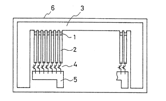
Fig. 1 is a plan view of an embodiment of a thermal head of the present
invention. This thermal head is constructed by forming thin-film heating
resistors 1. These are made of a material having metallic characteristics
of electric conductivity at a lower temperature of about 300 C and non-
metallic characteristics at a higher temperature such material being, for
example, vanadium oxide doped with about 0.1% of Cr relative to V. The
resistors are formed over a substrate 6 made of glazed alumina ceramics, by
connecting one terminal of each heating resistor 1 with an individual
electrode 2 and the other terminals of the resistors with a first common
electrode 3, and by connecting the individual electrodes 2 with through
current switching elements 4, such as transistors, to a second common
electrode 5. The thermal head need not be equipped with the switching
elements 4 and the second common electrode 5, instead these elements may be
separately provided in the recording apparatus.
-- 7 --
PAT 16161-1
: . .:~; .. , .. -
The first common electrode 3 is fed with a plus potential whereas the
second common electrode 5 is fed with a minus potential, and voltage pulses
are applied to the aforementioned heating resistors 1 by switching the swit-
ching elements 4. When voltage pulses are applied to the heating resistors
1, a suitable power consumption is caused by the applied voltage and the
resistances of the heating resistors 1, as in the thermal heads oE recording
devices of the prior art, to generate the Joule heat so that the heating
resistors 1 begin to rise in temperature.
Fig. 2 is a graphical representation showing the changes of the surface
temperature of the heating resistors 1 with time, according to a pulse
applied to the thermal head of Fig. 1. In Fig. 2, symbol Tc designates the
temperature of the metallic/non-metallic phase transition during electric
conduction of the heating resistors. Symbol ton designates the time of
starting the application of pulses. Symbol tp designates the time at which
the surface temperature of the heating resistors reaches the above-specified
phase transition temperature (Tc). Symbol toff designates the time to the
end of the pulse application. For the period between the time tp and the
time toff~ the heating resistors 1 repeat the metallic/non-metallic phase
transitions from the higher to lower temperatures and vice versa so that
their surface temperature stabilizes in the vicinity of the aforementioned
phase transition temperature Tc. The actual temperature of the heating
resistor may be raised to a slightly higher level than the level Tc by
either the heat capacity of the structural member at the periphery of the
heating resistors themselves or thermal inertia due to the thermal resis-
tance. The surface temperature of the heating resistors reaches the level
Tc of about 300 C for a time period as short as about 0.5 millisecs from the
time ton (unless a heat absorber such as heat-sensitive paper is brought into
contact with the heating resistors), when the heating resistors 1 have an
area of 0.015 mm2 corresponding to the heating resistor density of 8 dots/mm,
and a resistance of about 1,0001~ at the lower temperature, and where the
applied voltage is 20 V. This time period varies between individual thermal
head constructions because the local thermal characteristics such as the
thermal resistance or heat capacity of the heating resistors vary in depen-
dence upon the glazing thickness of the glazed substrate 6 of the thermal
head or the thickness of the protecting layer coating the surfaces of the
-- 8 --
PAT 16161-1
~ d J J ~
heating resistors 1. Since, however~ the peak temperature of the heating
resistors 1 is determined by the aforementioned phase-transition temperature
Tc f the material forming the heating resistors, such temperature does not
depend upon the aforementioned thermal characteristics of the thermal head
S or the structure of the thermal head.
Further, the variation of the thermal characteristics of the thermal
head appears as the temperature rise gradient from the time ton to the time
tp, i.e., at the time tp.
In the direct heat-sensitive recording system, the color developing
mechanism is the chemical reaction of a coloring agent due to the heat and
the reaction rate depends upon the temperature. In the thermal transfer
recording system, the recording mechanism is the physical phase change such
as the melting or sublimation of the ink and is dominated by the temperature
of the ink. Therefore, the effect of the variation of the thermal charac-
teristics on the recording characteristics is far smaller than in the thermalheads of the prior art in which the peak temperature of the heating resistor
fluctuates.
On the other hand, the variation of the resistance of the heating
resistors may exist not only in the thermal head of the thermal recording
apparatus of the prior art but also in the thermal head of the thermal
recording apparatus of the present invention, in dependence upon the thick-
ness of the resistive films. However, this variation appears only as that
of the period from the time ton to the time tp in the thermal head in the
present invention so that the peak temperature of the heating resistor does
not vary. If it is intended to strictly reduce the variation of the
temperature
rise gradient, i.e., the variation of the time tp due to the resistance
variation of the heating resistors, the applied voltage may be adjusted and
set to make the electric power uniform according to the magnitude of the
resistance of the heating resistors in the metallic electric conductivity
phase of the heating resistors at the lower temperature.
As has been described hereinbefore, the effects of the thermal
characteristics variation and resistance variation of the thermal head upon
the recording characteristics are remarkably small in the case of the
thermal head of the present invention. For the larger applied pulse width,
i.e., the longer time period for the time ton to the time toff of Fig. 2, as
_ 9 _
PAT 16161-1
,<J i~ 3 ,.3 ~j~
compared with the temperature rise period from the time ton to the time tp,
the more the changing and varying rates of the holding time period (toff ~
tp) of the peak temperature (which contributes the most to the recording
characteristics) are reduced, the more the recsrding quality is improved.
In the embodiment described above, the temperature for the
metallic/non-metallic phase transition of the heating resistors is set at
about 300 C. In the case of a thermal head required for a higher recording
speed, however, the heating resistors used have a higher phase transition
temperature of 400 to 450 C so that their resistance may be lowered (or the
applied voltage may be raised) to increase the electric power. Then, at a
higher temperature rise rate and at a higher peak temperature, the coloring
reaction of the heat-sensitive paper is sufficiently effected for a shorter
time so that the peak temperature holding time can be retained for a shorter
applied pulse width (toff - ton) to ensure a uniform recording operation.
By contrast, in a thermal head of lower speed and power consumption, the
power consumption rate in the heating resistors may be reduced by dropping
the applied voltage (or by increasing the resistance of the heating
resistors), or the aforementioned phase transition temperature may be
dropped to about 250 C. Alternatively, these two methods may be combined.
Figs. 4(A) and 4(B) are a partial plan view and a partial sectional
view of a modified thermal head in accordance with the invention.
The thermal head has a monitor o between the heating resistor 7 and the
individual electrode 2. The heating resistor 7 is made of ordinary resistive
material such as tantalum nitride. The monitor ô is made of the material
having the metallic/non-metallic phase transition used in the heating
resistor shown in Fig. 1 and is set to have a lower linear resistance than
that of the heating resistor 7. Therefore, when the power is applied between
the common electrode 3 and the individual electrode 2, the heat contribut--
able to the recording is generated mainly in the heating resistor 7 and the
monitor 8 generates a far lower heat than that of tha heating resistor 7.
If the material used to make the monitor 8 could form a film having a lower
sheet resistance (such as several tens mm ~ lower) than that of the heating
resistor 7, the individual electrode 2 could also be made of the material of
the metallic/non-metallic phase transition without differentiating it from
the monitor 8.
-- 10 --
PAT 16161-1
I'J''iJ ~
When the voltage is applied to the heating resistor 7, the heating
resistor 7 is heated by the Joule heat and the temperature of the monitor 8
is raised by the heat generated by the heating resistor 7. If the metallic/-
non-metallic phase transition temperature of the monitor 8 is 200 C, the
electric current flows till the temperature of the monitor 8 reaches 200 C.
When the temperature of the monitor 8 reaches 200 C, the current is substant-
ially blocked by the low non-metallic electric conducti~ity of the monitor 8
so as to interrupt the generation of the Joule heat. When the temperature
of the monitor 8 falls below 200 C, the current flows again to cause the heat
generation of the heating resistor 7. Thus, the temperature of the monitor
8 is held at the temperature of 200 C while the voltage is being applied.
Therefore, the temperatura of the heating resistor 7 is substantially cons-
tant at a higher temperature that at least that of the monitor 8 so that the
surface temperature of the heating resistor 7 cannot exceed the constant
level but is controlled. The accuracy of the temperature control of the
heating resistor 7 becomes higher as the monitor 8 is located closer to the
heating resistor 7, and the monitor 8 may be disposed in the burn area of the
heating resistor 7.
Fig. 5 shows a burn point area of the modified thermal head of the
present invention. The thermal head has monitors 8 made of the a-foresaid
material having the metallic/non-metallic phase transition, located at the
two sides of the heating resistor 7, the latter being made of ordinary
resistive material such as tantalum nitride.
In the case of the embodiment thus far described, the monitor 8 is
disposed in contact with one side of the heating resistor but may be disposed
at the two sides, as shown in Fig. 5. In case the electric conductivity of
the material of the metallic/non-metallic phase transition used in the
monitor 8 is not sufficiently small and an electric current leaks even at a
higher temperature to raise the temperature of the heating resistor contin-
uously, or in case the monitor 8 is heated by the leakage current at thehigher temperature~ it is preferable from the stand-point of the temperature
control that the monitors 8 be disposed at both sides of the heating resistor
7, as shown in Fig. 5, to enhance the current bloc~ing ability.
Figs. 6(A) and 6(B~ show a burn point area of a further modified thermal
head of the present invention. This embodiment differs from that of Fig. 5
-- 11 --
PAT 16161-1
~ 3
in that electrodes 22 are located between the heating resistor 7 and the
monitors 8, but the behavior of the monitor 8 by the heating of the heating
resistor 7 is unchanged. Especlally in case the materials of the heating
resistor 7 and the monitor 8 may possibly change their characteristics as a
result of chemical reactions at high temperature, this embodiment is more
effective because the electrode 22 may be made of a stable metal such as
gold in combination with at least the material of the monitor 8 to separate
the monitor 8 from the heating resistor 7.
Fig. 3 illustrates how the surface temperature of the heating resistor
changes when the aforementioned thermal heads are driven with continuous
pulses.
The peak temperature is constant for the time period from the first
pulse to the n-th pulse, and the temperature-rise time caused by the first
pulse is longer because of the lower initial background temperature of the
heating resistors, but the heating curves are substantially identical on and
after the second pulse. Thus, the self-control can be made to provide a
constant heating temperature without any driving control. The relatively
long duration of the heating temperature-rise time by the first pulse causes
no special problem even in the sublimation-type continuous tone printer. In
case of strict recording density management is necessary, the applied pulse
width may be elongated more for the temperature-rise time only in the case
of the first pulse, i.e., where the background temperature is low, to
control the peak temperature holding time at a uniform value.
In recording apparatus for continuous tone recording, it is usual to
control the continuous tone according to the width of the applied pulses no
matter whether the recording is of the direct heat-sensitive type or the
sublimation transfer type. In the thermal head of the prior art, the
continuous tone control is difficult to achieve due to the fluctuations of
the peak temperature of the heating resistor because the peak temperature
will change together with the pulse width.
In the thermal head of the present invention, on the other hand, the
peak temperature is self-controlled to a constant level so that the
continuous tone can be more finely controlled with respect to time, only
independently of the peak temperature. In the example of the prior art,
some relative density control performs sixty four continuous tones, but the
- 12 -
PAT 16161-1
,
~J ~3~
,,
absolute density control is restricted to sixteen continuous tones at most.
In the thermal head of the present invention, however, the absolute density
control can be facilitated to one hundred and twenty eight continuous tones
or two hundred and fifty six continuous tones, as will be apparent from the
foregoing description. Fig. 13 is a diagram showing the waveforms of the
surface temperature of the heating resistor with respect to the pulse width
applied to the heating resistor, when the thermal head of the present
invention is utilized in the continuous tone recording. A heating resistor
temperature waveform (18-1) caused by the first gradation pulse (19-1)
starts its cooled drop midway of the temperature rise. Even with this
gradation pulse setting, the continuous tone accuracy is high if the heating
peak created by pulses to the N-th continuous tone is within the time range
controlling the peak temperature flat.
The aforementioned embodiments are embodiments controlling uniformly
the temperature generated by the heating resistor of the thermal head to
apply the heat to the recording medium such as the heat-sensitive recording
paper or the ink donor sheet in a direct heat-sensitive recording system or
a thermal transfer recording system.
In a powered thermal recording system in which the heat-sensitive
recording paper or the ink donor sheet having a heat resistive layer itself
is heated by applying the power to the heat resistive layer, again the
heating temperature of the heat resistive layer is made uniform by making
the heat resistive layer of the material having the metallic/non-metallic
phase transition so that it can record uniformly. The present invention as
it applies to powered thermal recording will be described in connection with
the following embodiments.
Fig. 15 shows a powered thermal recording device of the present
invention. A head 60 has a pair of electrodes 61, 62. A powered heat-
sensitive recording sheet 50 is composed of a base sheet 52 such as a
plastic sheet, a coloring recording layer 51 disposed on one surface of the
base sheet 52 and a heat resistive layer 53 disposed on another surface of
the base sheet 52. The coloring recording layer 51 is comprised of coloring
agent compound and binder. The heat resistive layer 53 is made of the
material having the metallic/non-metallic phase transition. The powered
heat-sensitive recording sheet 50 is sandwiched between a platen SS and the
- 13 -
PAT 16161-1
head 60 and is carried by rotating the platen 55. When voltage pulses are
applied between electrodes 61, 62, the electric current flows from the
portion of the heat resistive layer 53 coming in contact with the electrode
61 to the portion of the heat resistive layer 53 coming in contact with the
electrode 62 so that the heat is generated in the aforementioned area of the
heat resistive layer 53. The heat is transmitted to the coloring recording
layer 51 through the base sheet 52 so that the area of the coloring recording
layer 51 corresponding to the heated area of the heat resistive layer 53
generates color with the chemical reaction of the coloring agent due to the
heat.
Fig. 17 shows a powered thermal transfer recording device of the
present invention. An ink donor sheet is composed of a base sheet 54 made
of metal having lower conductivity than that of the heat resistive layer 53,
the heat resistive layer 53 disposed on one surface of the base sheet 54 and
an ink layer 66 disposed on another surface of the base sheet 54. The ink
layer 66 is made of the thermal melting ink. The ink donor sheet and a
recording paper 67 are sandwiched between a platen 55 and a head having an
electrode 61 and is carried by rotating the platen 55. Further, an electrode
65 is disposed in contact with the heat resistive layer 53. When voltage
pulses are applied between electrodes 61, 65, the electric current flows from
the electrode 61 to the electrode 65 through the heat resistive layer 53 and
the base sheet 54. The electric current flows mainly downwardly in the heat
resistive layer 53 because the base sheet 54 has lower conductivity than that
of the heat resistive layer 53. Therefore, the portion of the heat resistive
layer 53 being in contact with the electrode 61 generates the heat. The heat
is transmitted to the in~ layer 66 through the base sheet 54 so that the
portion of the ink layer 66 corresponding to the electrode 61 is melted by
the heat and the melted ink is transferred to the recording paper 67.
In the devices shown in Figs. 15 and 17, the peak temperature of the
heat resistive layer 53 is always constant independently of the applied
voltage, the power application time, the sheet resistance of the heat
resistive layer 53, the temperature of the head, and the temperature of the
platen 55 and the environment~ because the heat resistive layer 53 is made
of the material having the metallic/non-metallic phase transition.
- 14 -
PAT 16161-1
,
Fig. 16 shows a modified head for applying the power in the powered
thermal recording system. The head is composed of a supporting substrate
63, electrodes 61 disposed on the supporting substrate 63 for applying the
power, and a portion 64 disposed at a chamfered end of each electrode 61.
S ~ach portion 64 is made of the material having the metallic/non-metallic
phase transition, has the function of interrupting the electric current
based on its temperature and is in contact with the powered recording medium
having the heat resi~tive layer. When the applied voltage pulse is applied
to the heat resistive layer of the powered recording medium by the head, the
heat resistive layer generates the heat. The temperature of the portion 64
rises in company with the temperature rise of the heat resistive layer. If
the temperature of the portion 64 reaches the phase transition temperature
of the material having the metallic/non-metallic phase transition, the
portlon 64 changes to non-metallic phase and interrupts the electric
current. As a result, the head can control the peak temperature of the heat
resistive layer to a constant level. In this case, the heat resistive layer
can be made of conventional material such as tantalum nitride.
Here, the aforementioned material having the metallic/non-metallic phase
transition is exemplified by a compound of vanadium oxide. This vanadium
oxide will change the metallic/non-metallic electric conductivity, lf doped
with a minute amount of Cr, in a region at a higher temperature than roorn
temperature. The doped vanadium oxide has a non-metallic electric conduc-
tivity at a higher temperature and a metallic electric conductivity at a
lower temperature. Both vanadium and its oxide are refractory materials and
can be used to make the heating resistors. The heating resistor film can be
formed by the thin-fllm process such as the sputtering or by the thicX-film
process of spreading either a paste, which is prepared by powdering the
material and mixing it with a binder, or an organic material. In either
case, the filmed vanadium oxide component is required to have at least a
polycrystalline structure. The sputtering process is exemplified either by
sputtering an alloy target of metallic vanadium and chromium or a metallic
vanadium target having buried chromium with a gas mixture of argon and
oxygen, or by high-frequency sputtering a target, which is sintered with
vanadium oxide powder and chromium oxide powder, with argon gases or a gas
mixture of argon and a minute amount of oxygen. In either sputtering
- 15 -
PAT 16161-1
method, the temperature to be filmed is desirably at several hundreds C or
higher so as to crystallize surely.
In the case oE doping a proper amount of Cr, the electric conductivity
will change by 2 to 3 orders of magnitude at the aforementioned phase
transition temperature. If, therefore, the material is used to make the
heating resistor of the thermal head and the heating resistive layer of the
heat-sensitive papers, the power to be consumed around the aforementioned
phase transition temperature in the state of constant voltage application
changes by 2 to 3 orders of magnitude and it follows from this that it
substantially controls the heating state and non-heating state from the
thermal recording standpoint. The phase transition temperature can be
changed according to the ratio of the doping Cr so that the pea~ temperature
of the heating resistors can be set. Further, the phase transition
temperature shifts to the lower temperature side as the ratio of the doping
Cr increases. Vanadium oxide having no Cr dopant has its resistance
changing at a small rate, giving gentle changes in temperature. Since,
however, the resistance rises by one order of magnitude from the lower to
higher ~emperatures across about 400 C, the undoped vanadium oxide can also
be used in the thermal head of the present invention.
Fig. 14 is a diagram showing the temperature changes of the linear
resistance of the heating resistor exhibiting the metallic/non-metallic phase
transition. The linear resistance itself presents a reference because it is
changed with the film thickness and the line width. However, the vanadium
oxide doped with about 0.5a of Cr has its resistance changed ~y 3 orders at
about 150 C, as indicated by a linear resistance characteristic curve 31.
The temperature range for causing the resistance change with Cr dopant is so
changed with the incrèase of the Cr dopant that it is gradually shifted to
the lower temperature side. If the doping ratio of Cr to V of the vanadium
oxide exceeds several percent, the change whereby the resistance increases
from the lower to higher temperatures disappears so that the object of the
present inventlon cannot be achieved. Since the doping ratio of Cr changes,
the temperature characteristics of the resistance change as has been
described hereinbefore, the change of the linear resistance may be made
gentle to occur over a temperature range of certain width, as indicated by
curve 32 in Fig. 14, by the inhomogeneity of Cr doped in the vanadium oxide,
- 16 -
PAT 16161-1
3 rJ ~
even if the doping ratio oE Cr to V in the vanadlum oxide is 0.5~. With
this gentle change, the object of the present invention can be achieved.
When a heating resistor having a side of several mm below 1, for example, is
to be energized and heated, its resistance change appears gentle, as
S indicated by the curve 32 of Fig. 14, in case the above-specified material
is used to make the heating resistor of the thermal head, because the
temperature rise is not spatially uniform in the heating resistor. In this
case~ too, the temperature rise and the energization stop are caused in a
micro manner so that the heating resistor can realize the temperature rise
or not without any problem.
Further, the material having the metallic/non-metallic phase transition
characteristic is a mixed crystal, represented by BaxPbl_xTiO3, composed of
barium titanate and lead titanate. In this case, it has the phase transition
temperature of about 300 C and the electric conductivity changes by 2 to 3
orders at the phase transition temperature when x is equal to 0.55.
Next, another driving method for the thermal head or the power supply
head in the thermal recording method of the present invention will be
described in connection with a particular embodiment thereof.
Fig. 7 is a top plan view showing the thermal head in which the
switching elements of the aforementioned thermal head of Fig. 1 are in the
form of thyristors. The thyristors 10, which are connected one-on-one with
the individual heating resistors 1 having the metallic/non-metallic phase
transition characteristics, are turned on by inputting a turn-on signal to
their gates 11 at an arbitrary timing according to the recorded data. The
first common electrode 3 is fed with a plus potential, and the second common
electrode 5 is fed with a minus potential. When the thyristors 10 are turned
on, the heating resistors 1 are substantially fed with the difference between
the plus and minus potentials so that they start to pass the electric
currents. Upon this energization, the heating resistors 1 generate the Joule
heat so that their temperature rises are started. When the temperature of
the heating resistors 1 reach the metallic/non-metallic phase transition
temperature of the material making the heating resistors, the value of the
current flowing through the heating resistors drops by 2 to 3 orders if the
heating resistors are made of vanadlum oxide doped with Cr, for example. If
elements having suitable turn-off characteristics are selected as the
- 17 -
PAT 16161-1
thyristors 10, these thyristors 10 are turned off by interrupting the current
through the heating resistors 1. Once the thyristors 10 are turned off, the
heating resistors 1 cannot be energized again so long as the turn-on signal
is not inputted to the gate 11, so that heat generation from the heating
resistors 1 is interrupted. In other words, the heating resistors 1
automatically interrupt their heat generation, when they are energized to
have their temperature reaching the aforementioned phase transition level,
and are cooled down to stand-by for the subsequent input of the thyristor
turn-on signal.
Fig. 8 is a diagram showing the time changes of the surface temperature
of the heating resistors when the heating resistors 1 of the thermal head
shown in Fig. 7 are continuously driven by the aforementioned thyristors 10.
Numeral 13 indicates the surface temperature of the heating resistors, and
numeral 14 indicates the gate input signal to the thyrlstors 10, i.e., the
timing signal for starting the heating. TC designates the aiorementioned
phase transition temperature. No matter what timing gate input pulses 14
might be inputted, as is apparent from Fig. 8, the surface temperature of the
heating resistors would not exceed the level Tc, but the temperature curve in
the vicinity of the peak temperature, which is one oE the most important tem-
peratures for the thermal recording, is identical for either heat generation.
In the foregoing description of the temperature rise and fall curve, ithas been clarified that the curve is not influenced by the heating history of
a specific one of the heating resistors. However9 the rise and fall curves
of the peak temperature of the specific heating resistor 1 are not influenced
to realize the uniEorm heat generation at all times even for the simultaneous
heat generations, the histories of the past heat generations of the heating
resistors adjacent to or around the specific heating resistor, or the
temperature of the substrate 6 of the thermal head. Moreover, even if the
applied power variation accompanying the variation of the resistances of the
heating resistors and the thermal characteristic variation accompanying the
variation of the glazed layer thickness exists between either the individual
heating resistors or the individual thermal heads, the peak temperatures to
be determined by the aforementioned phase transition temperature and the
heating waveforms in the vicinity of the peak temperature are uniform.
- 18 -
PAT 16161-1
3 ,3 ~
In the case of the thermal head having the combination of the
aforernentioned material for the metallic/non-metallic phase transition and
the thyristor, the peak temperature of the heating resistor is always
constant. As a result, under the identical thermal driving conditions,
the recording density will be different in the case where the coloring
sensitivity is different due to differences in the various kinds of heat-
sensitive paper. As shown in Fig. 12, the surface temperature of the heating
resistors changes with the voltage applied to the heating resistors, as
indicated by temperature curves (15, 16 and 17). In case a heat-sensitive
paper of standard sensitivity is used, for example, the aforementioned
applied voltages are so set as to follow the curve 16 of the heating resistor
surface temperature. In the case of the heat-sensitive paper of low sensi-
tivity, the applied voltage is set by lowering the applied voltage to extend
the temperature maintenance time in the vicinity of the peak temperature, as
indicated by the curve 17. In the case of the heat-sensitive paper of high
sensitivity, on tha other hand, the applied voltage is raised to reach the
peak temperature instantly, as indicated by the curve 15. The thermal head
can correspond to the difference in the recording sensitivity
characteristics of the heat-sensitive paper solely by changing the applied
voltage.
Another effective method for coping with the sensitivity difference is
also exemplified by a preheat of the heat-sensitive paper or the in~ donor
sheet immediately before heating of the heating resistor. In the case of
low heat-sensitive paper, for example, no change in the voltage applied to
the heating resistor can be sufficient if the aforementioned preheating
temperature is set at a high level.
The thyristor can be utilized in switching the power applied to the
head 60 in the powered thermal recording device shown in Fig. 15. In this
case, a circuitous current path is left so that an extreme curren~ reduction
cannot be deslred, even if a minute portion corresponding to one picture
element turns nonconductive, because the heat resistive layer 53 is widely
planar. It is, therefore, necessary to provide a circuit having a large
turn-off current. Further, it can reduce the circuitous current, can ensure
the current blocking property of the heat resistive layer 53 and can achieve
the fine recording property by which the heat resistive layer 53 is divided
into a plurality of islands 53a having a similar size to the recording
-- 19 --
PAT 16161-1
l~f ~ .J 1~ ~
picture element, as shown in perspective view in Fig. 18.
Fig. 9 shows one embodiment of the heating drive control circuit, and
Fig. 10 is a driving timing chart oi the thermal head using the drive control
circuit. In Fig. 9, reference numeral 35 designates serial-in parallel-out
S shift registers having a serial input terminal 31 and a shift clock terminal32. AND gates are fed with the parallel outputs of the shift registers 35
and the heating timing signal coming from an input terminal 33, each AND
gate having an output terminal 34. This output terminal 34 of the ~ND gate
36 is connected with the gate 11 of a thyristor 10, which in turn is
connected with the heating resistor, so that it can turn on the thyristor 10
selectively. In Fig. 10, numeral 41 designates video data of one recording
line, and numeral 42 designates a shift clock. If the video data 41 are
arrayed in the aforementioned shift registers 35, a heating timing signal 43
is inputted in the form of pulses of several microsecs so that the input
signal 44 of the gate 11 of the thyristor 10 is outputted in the form of
~ulses of several microsecs from the aforementioned output terminal 34 in
accordance with the content of the video data 41. When the input signal 44
is outputted, the drive control circuit shown in Fig. 9 can be released from
the heating operation and shifted to a series of the aforementioned
preparations for the next line.
The drive control circuit of the conventional thermal head is enabled
to perform the high-speed processing by having a latch circuit so that the
recording video data may be written in parallel with the heating operations
of the heating resistors. ~owever, in the present invention, the high-speed
parallel processing can be accomplished without the latch circuit by
combining the heating resistors of the metallic/non-metallic transition type
and the thyristors. As a result, it is posslble not only to reduce the size
and drop the cost of the drive control circuit but also to reduce the size
of the thermal head embodying the drive control circuit.
In all the embodiments excepting the aforementioned powered recording
one, the peak temperature of the heating resistors is unvaried regardless o~
whether or not the recording medium such as the heat-sensitive papers acting
as an endothermic source might contact the heating resistors. As a result,
the thermal head of the present invention is freed from the deterioration or
breakage of the heating resistors due to an abnormal rise of the peak
- 20 -
PAT 16161-1
;~'J ;~ .3
temperature, which might otherwise be caused in the state of no paper feed
of the heating resistors of the thermal head of the prior art. Moreover, a
high reliability is exhibited, even in the event of malfunction or runaway
of the drive control circuit of the CPU due to noise.
S This effect is commonly applied to the powered thermal recording by
enhancing the reliability and safety of the apparatus with neither the
abnormal heat generation nor firing of the powered heat-sensitive recording
paper due to runaway of the circuit nor the breakage of the parts such as
the platen.
Fig. 11 is a top plan view showing an essential portion of the thermal
head, in which the heating simulator 23 made of the material having metal-
liclnon-metallic phase transition is arran8ed in series with the individual
electrode 2 at a position removed from the heating resistor 7 made similar
to that of Fig. 4. The aforementioned heating simulator 23 is given a linear
resistance lower than that of the heating resistor 7 and higher than the
individual electrode 2. If the heating resistor 7 is energized to generate
the heat, the heating simulator 23 starts a gentle heat generation. If the
temperature of the metallic/non-metallic phase transition of the heating
simulator 23 is set at about 120 C, for e~ample, the heating simulator 23 is
heated by the Joule heat to about 120 C simultaneously with the temperature
rise of the heating resistor 7, so that it is transferred to the non-metallic
phase. As a result, the current flowing through the individual electrode 2
connected in series with the heating simulator 23 and the heating resistor 8
can be blocked like the aforementioned individual embodiments to realize the
heating control of the heating resistor 7. The heating and cooling behaviors
of the heating simulator 23 are substantially similar to those of the
aforementioned heating resistor 7 but are highly different in the peak
temperature. The heating simulator 23 is not directly influenced by the
temperature changes due to the voltage pulse applied to the heating resistor
7 because it is positioned apart from the heating resistor 7. The heating
simulator 23 is most seriously influenced by the background temperature
resulting from the flow heat storage or rise of the thermal head substrate
due to the heat storage around the exothermic simulator itself, the environ-
mental temperature or the heat generation of the heating resistor. As a
result, the heat generation by the heating resistor cannot be completely
- 21 -
PAT 16161-1
I~`J i~
controlled, but a sensitive reaction is exhibited for the fluctuations oE
the apparent coloring sensitivity due to the temperature fluctuations of the
heat-sensitive papers accompanying the fluctuations of the environmental
temperature and the inside temperature of the recording apparatus. As to
the influences of the heating resistors around or adjacent to the heating
resistor being activated, the peripheral heating simulators thermally inter-
fere with one another to affect the heating simulations of the grouped
heating resistors, if the heating simulators 23 are aligned with one another
in positional relationship of the heating resistors 7, as shown in Fig. 11,
for example. Since, moreover, the heating simulator is not heated to a high
temperature but has a small thermal impact, it is advantageous in the
heat-resisting reliability for the material of the metallic/non-metallic
phase transition. Tf a protecting layer over the heating resistor is
likewise formed over the heating simulator, the reliabilities are improved
against oxidation or thermal degradation of the heating simulator and
against the impact of the crystalline structural change accompanying the
aforementioned phase transfer.
In all the embodiments thus far described, the characteristics of the
material used in the heating resistor, the heat resistive layer, the leading
end of the power supply electrode, the wiring line and the heating simulator
need not have their electric conductivity changed discontinuously at the
predetermined temperature but may have the conductivity changed continuously
within a temperature range having a predetermined width. In order to ensure
the exhibition of the effects of the present invention, the electric
conductivity is at least 1 order or desirably 2 orders or more. This
necessary change means the practically minimum ratio of the resistance which
is required by the power consumption (or energy) to enable the heating
temperature rise to reach a level necessary for the recording to the
resistance at which the power consumption (or energy) becomes lower than the
level for maintaining the temperature of at least the heating resistor or
the heat resistive layer at the temperature level relating the recording
under the condition of a constant applied voltage. In short, in order to
obtain the advantages of the present invention, it is important to make use
of the material which has its electric conductivity changed at the
aforementioned minimum ratio in dependence upon the temperature.
- 22 -
PAT 16161-1
~ w ~ ~3 ~
According to the present invention, as has been described hereinbefore,
the following excellent effects can be exhibited:
(1) The peak temperature of the heating resistor can be uniformly
controlled for all the temperature environments in which the heating resistor
of the thermal head or the heat resistive layer of the powered heat-sensitive
recording sheet is placed;
(2) The variation of the recording characteristics can be suppressed
for the thermal characteristic variation such as the glazed layer of the
thermal head:
(3) The recording characteristic variation can also be suppressed for
the variation of the sheet resistance of the heat resistive layer;
(4) Highly precise density gradation control is facilitated;
(S) The heating drive control circuit can be simply constructed to
reduce the dimensions of the circuit, the thermal head and the power supply
head substrate;
(6) The recording can be speeded up with ease;
(7) Temperature data collection circuits or recording density
correction circuits such as for temperature detection of the recording
apparatus need not be used so that the apparatus can be provided with a
small size and at a reasonable cost; and
(8) A high reliability and safety can be obtained against the runaway
of the heating resistor.
PAT 16161-1