Note: Descriptions are shown in the official language in which they were submitted.
FLEXIBLE COUPLING FOR JOINING A
DRIVING MEMBER TO A DRIVEN MEMBER
FIELD OF THE INVENTION
This invention relates in general to flexible
couplings for joining a driving shaft to a driven Shaft,
which may be misaligned relative to each other. More
particularly, it relates to a coupling of the type
employing one or more flexible disc elements which allow
high axial and/or angular displacement between the shafts
with increased torque transfer capability.
BACKGROUND OF THE INVENTION
When the axes of rotation of a driving and a
driven shaft are not in alignment, there are a number of
possible categories of such misalignment. One may be
considered parallel offset, that is, where the axes are
parallel to each other but spaced from one another in a
transaxial dir~ction. Another may be considered angular
offset, which is where ~tha axes are not parallel but
intersect at an angle, although the axes may lie in
parallel planes. The third is misalignmant in the axial
direction.
Numerous coupling devices have been developed
to transmit power from ar between two such shafts.
United States Patent No. 3,625,024 to Kikuchi, which
issued December 7, 1971, and United States Patent No.
4,321,805, which issued to Bossler, Jr. on March 30,
1982, disclose such coupling devices (also known in the
art as a "delta-flex°' coupling), but they are limited in
their torque carxying capabilities because the arms of '
the °'delta°' used to txansmi~t torque are long and are
subject to column buckling. Each of the ccauplings
includes an element having a single beam or column with
V-shaped elements at each of their ends for connection to
driving and driven elements, such as xotatable shafts or
_2_
hubs on such shafts. In each of these coupling elements,
a beam or column which connects the "v", is susceptible
to buckling under high torque loadings. This limits
torque carrying capability.
Another type of coupling provided to transfer
loads to accommodate axial misalignment or displacement
between a driving and a driven shaft or displacement
between a driving and a driven shaft is found in a series
of patents currently assigned to the Assignee of the
present invention. These are: United States Patents
Nos. 4,282,723: 4,317,339 and 4,331,004, which issued on
August 11, 1981, March 2, 1982 and May 25, 1982,
respect~.vely, to Richard Schmidt.
In the Schmidt devices the actual coupling
element, which is attached to hubs on each of a driving
arid a driven shaft, includes an annular portion and two
pairs of parallel arms. Whereas the arms themselves are
parallel, the pairs are not symmetrical. The arms are
sufficiently flexible to provide good axial and/or
angular displacement to compensate for the misalignment.
However, there are inherent limitations in the design
resulting in a limited ability to transfer high torque
loads. This results from the fact 'that regardless of the
direction of rotation, at least one pair of arms at all
times is in compression without any compensating tensile
component. The result is that under high torque
conditions, the arm under compression is susceptible to
buckling which, therefore, limits the load carrying
capacity of the entire coupling element. The Schmidt
type of device is also known as an open-end arm ar apen-
link type of coupling.
Diaphragm-type couplings are known which permit
large torque transmission, but are able only to handle
slight angular misalignment on the order of 1/4 degrees
to 1/3 degrees.
~~~~~ ~i~~~~
-3-
Flat metal discs, such as the Formsprag type,
are also well known, which offer high torque
transmission, but are not capable of handling severe
misalignments of driving and driven shafts. Also, in
flat disc couplings, the phenomenon of °'fretting" occurs.
There are two types of "fretting", i.e. (a) nuta~ting
around the bolt bearing washer, and (b) linear fretting,
which occurs by the rubbing together of one disc on
another (generating a shearing action) away from the
connection area of the disc. As the disc material rubs,
it oxidizes and disturbs the substrate, eventually
propagating a fatigue crack. This is especially
prevalent in discs having a thickness on the order of
.015" to .090". Coating on such discs may extend their
life, but they also deteriorate under the rubbing action.
I~t is an object of the present invention to
provide a coupling mechanism capable of transmitting high
torque loads whale compensating fax axial and/or angular
misalignment.
Tt is another object of the present invention
to provide a coupling mechanism which is capable of
'transferring torque loads in shear rather than either
tension or compression alone, to approximate a diaphragm--
type performance, while permitting higher angular
misalignment, and axial displacement, both continuous and
intermittent.
Still another object of the present invention
is to provide a coupling mechanism which is capable of
offsetting compression loads in each torque transmitting
member by a tensian load.
A still further abject is to provide a coupling
which eliminates fretting effects and being fatigue
adjacent to the means of attachment.
An added object is to provide a coupling which
can, in unidirectional applications, be assembled to
minimize fretting by placing all attachment elements such
-4-
as lobes in compressionp or alternatively to maximize
torque carrying capacity by placing all lobes in tension.
An additional object is to provide a constant
velocity coupling of a non-lubricated type.
SUMMARY OF THE TNVENTTON
The coupling device of the invention includes a
flexible coupling disc element or elements for use in
joining a driving member to a driven member, which
members may be misaligned. Each flexible coupling disc
element is formed into a plurality of lobes which are
interconnected by connector elements, which can take
various forms. In one preferred form, the lobes are
spaced from an inner ring (or hub portion) or outer ring
by generally radially extending connector elements. Each
lobe has a pair of arms joined together adjacent the
connector. They extend away from the connector in
opposite circumferential directions, and terminate in
free finds. This type of structure can be connected to
driving and driven members in such manner as to cause
force or torque transmission through the disc with shear
loading on the connector element or tensile or
compressive loading between the free ends of the lobes.
There are means at the free ends for connecting the lobes
selectively either to the driving and/or 'the driven
members.
The coupling device may include a first and a
second coupling member, respectively mounted to driving
and driven shafts. At least one intermediate flexible
disc element is preferably located between the coupling
members in the preferred embodiment, to which members the
other flexible disc members are also mounted. In one
form of the invention each coupling member has a
plurality of radially extending arms. At the free ends
of the arms of the lobes on the flexible disc element are
means for connecting the arms selectively to radially
~~~~~~v~
--5~
extending arms of the driving and driven coupling
members, respectively.
The above and other features of the invention
including various and novel details of construction and
combinations of parts, will now be more particularly
described with reference to the accompanying drawings and
pointed out in the claims. It will be understood that
'the particular misalignment compensating and high torque
transmission coupling device embodying the invention is
shown by way of illustration only and not as a limitation
of the invention. The principles and features of this
invention may be employed in varied and numerous
embodiments without departing from the spirit and scope
of the invention.
BFtTEF DES(;RIPTION OF TIE DRAWINGS
Figure 1 is a coupling mechanism representing
the prior art as taught in U.S. Patent 4,331,04 to
Schmidt.
Figure 2 is an end view thereof as viewed from
the left side of Figure 1.
Figure 3 is a flexible coupling member employed
in the prior art Schmidt device.
Figure 3A is a view of a typical Formsprag type
of flexible coupling member employed in the prior art.
Figure 4 is a flexible coupling member employed
in the coupling mechanism of the invention.
Figure 5 is the same form of flexible coupling
member as shown in Fig. 4 which can be employed in an
alternative attachment arrangement of the coupling
mechanism of the invention.
Figure 6 is another form of flexible coupling
member which can be employed in the coupling mechanism of
the invention.
~~?'~
Figure 7 is a preferred form of flexible
coupling member which can be employed in the coupling
mechanism of the invention.
Figure 8 is an end view of a preferred form of
the coupling mechanism of the invention employing the
flexible coupling member shown in Figure 7.
Figure 9 is a side view of the coupling
mechanism of Figure 8.
Figure l0 is an exploded perspective view of a
l0 preferred form of the coupling mechanism of the invention
employing an intermediate hub member.
Figure 11 is a view of a further form of
flexible coupling member of the invention which
eliminates the use of an inner ring element.
Figure 11A is a view of a further form of
flexible coupling member of the invention which
eliminates the use of an inner ring element.
Figure 12 is a view of a still further form of
flexible coupling member of the invention in which there
are two pairs of lobes used, and
Figure 13 is a view of a still further form of
flexible caupling member of t~ha invention in which twa
connector elements are used per lobe.
DETAI:GED DESCRIPTION OF THE INVENTION
Referring to Figs. 1, 2 and 3, the prior art as
represented by U.S. Patent 4,282,723 to Schmidt will now
be described. The Schmidt device comprises a flexible
coupling mechanism generally indicated as l0, which
connects a first shaft 12, which can be a driving shaft
(hereinafter sometimes referred to as Shaft A), to a
second shaft 14, which can be a driven shaft (hereinafter
sometimes referred to as Shaft B). Whereas the axis of
rotation 16 of the shaft 12 and the axis of rotation 18
of shaft 14 appear to be aligned, they may suffer from
w ~~ ~ ~~ aJ
-
any one or combination of the misalignments described
previously.
There are three basic members comprising the
coupling mechanism 10. They include a first coupling
member 20 (Fig. 1) and a second coupling member 22 which
are adjustably secured to shafts 12 and Z4 respectively
by set screws 24 or their equivalents. ~.n intermediate
flexible membex, generally indicated at 26, is located
between the first and second coupling members 20 and 22.
The first and second coupling members 20 and 22 are
substantially identical to each other, consequentially,
only one will be described here. Coupling member 20
includes a ring-shaped annular portion 28 having element
receiving portions in the form of spider-like arms 30
Z5 extending radially outwardly and approximately 120
degrees apart,
Whereas the first coupling member 20 has been
described in general and shown in Figure 2 in salid
lines, the companion coupling member 22 is shown for the
most part in dotted lines.
The prior art intermediate flexible coupling
member 26 will best be seen in Figure 3. It includes a
generally ring-shaped annular portion 32 which has a
cylindrical interior opening 34.
The intermediate member 26 also includes a
first air of opposed generally para11e1 arm portions 36,
36' having attached ends 38, 38' respectively connected
to the annular partion 32. each arm 36, 36' also has a
free end 40, 40', respectively, provided with the
openings 42, 42' respectively therein to receive a bolt
to attach the arms 36, 36' to two of the three projecting
spider-like arms 30 of the driving coupling member 20 as
shown in Figures 1 and 2. The pair of free ends 40, 40'
on the arms 36, 36°, respectively, are each connected to
the spider arms as shown in the upper right and lower
left quadrants of Figure 2, the connection being
G 2 i , i
~~J~ ~~.~~;~~1~
-g_
accomplished by bolts 44. The remaining arm 30 (lower
right quadrant of Figure 2) remains unconnected.
The intermediate member 26 further has a second
pair of opposed generally parallel arm portions 56, 56',
having attached ends 57, 57' respectively connecting such
arm portions to the annular portion 32. Each arzn 56, 5E>'
also has a free end 54, 54' respectively, provided with
the openings 52, 52' respectively, therein to receive a
bolt to attach the arms 56, 56' to two of the three
projecting spider-like arms 33 of the driven coupling
member 22, as shown in Figures Z and 2. The pair of free
ends 54, 54' on the arms 56, 56' respectively, are each
connected to the spider arms 33 as shown in the lower
right and upper left quadrants of Figure 2, the
connection being accomplished by bolts 43. The remaining
arm 33 (upper right quadrant of Figure 2) of the driven
coupling member remains unconnected.
Tn operation, the driving shaft 12 transmits
torque through coupling member 20, the arm 30, to arm
portion 3~ of the intermediate member 26 (assuming a
counter-clockwise rotation as shown in figures 2 and 3)
through the bolt connection. Tha torque is then
transmitted through the halt connection. The torque is
than transmitted through the attached ends 38 and 57 to
arm 56 and via arm 33 of the driven coupling member 22 to
the shaft 14. At the same time, torque is also
transmitted through arm 30 to arm 36 and end 38' to ring
portion 32 and via end 57' to arm 56' and via another arm
33 and second coupling member 22 to shaft 14.
With the direction of rotation being counter-
clockwise as viewed in Figures 2 and 3, as indicated by
the arrows, the arm is in tension and the arm 36' is in
compression, as indicated respectively by the letters "T"
and "~'° in Figure 3. Also, the arm 55 is in tension and
the arm 56° is in compression as indicated by the letters
T and C in Figure 3. xn other words, the coupling member
~7 a .
~ ~~ ~.:~ ~ ~J ~~
20 pulls the arm 36 and pushes the arm 36' by means of
the bolts which pass through the free ends 40, 40' of the
arms 36, 36', respectively. This renders arm 36'
susceptible to columnar buckling, and thus limits high
torque transmission. Also, the arm 56 is in tension and
the arm 56' being in compression is also susceptible to
columnar buckling. The foregoing shortcoming of the
Schmidt coupling is one of the aspects which the present
invention intends to improve upon.
While only a sketchy description of the
apparatus and function disclosed by Schmidt has been
given reference should be had to the patent cited for a
more complete description of the function as well as haw
it behaves in transmitting torque between misaligned .
shafts. Tt should be noted that as described above the
spider arm 30 in the lower right-hand quadrant of Figure
2 is unconnected to the intermediate coupling member.
The spider arm 33, which is part of the second coupling
member 22 and shown in the upper right-hand quadrant of
Figure 2, is also coupled.
As shown in Figure 3A, another type of prior
art device is the Formsprag type of intermediate flexible
member which can be used singly or in a pack. The
flexible member may be in the form of a metal flexible
disc 26' having a circular opening 34' and provided with
four holes 42'°, 42 " ', 52'° and 52 " ' for receiving
bolts to be mounted to a driving and driven shaft
coupling element. The convention mentioned abave is
used, i.e. the connection to the driving shaft is shown
by the letter "A" and the connection to the driven shaft
is shown by the letter "B". Portions of the disc 26' are
respectively placed in tension and in compression,
assuming a counter-clockwise driving motion as shown by
the arrow in Figure 3A. The tensile and compressive
forces are indicated by the letters '°T°' and "C".
Although in such a type of device the sides in tension
E
~S ~~ N 3
-10-
restrain the sides in compression from collapsing because
of the geometry to obtain good torque transmission, there
is very limited ability to accept angular misalignment.
This is another feature found in the prior art which the
invention is intended to overcome.
In applicant's invention the use of lobes as
shown in Schmid~t is also found to be advantageous, but
there is provided in connector element to each lobe to
interconnect them which is positioned between the ends of
the lobes to reduce the column length. ~bviously a
halfway positioning is optimum. This provides a buckling
constraint. The column length is the distance between
the connecting bolt or washer outer diameter, and the
inner end of the connector neck, instead of the entire
length of the lobe arm as shown in the Schmidt device.
This effectively reduces the column length subject to
buckling by 2/3rds, but reduces the effective flexing ram
by only 50%. A lobe/connector arrangement is thus
preferred to abtain more torque. It is thus found that
the shorter the length of the column arm, the more torque
can be transmitted. Another feature of the invention is
the use of an annular ring element to provide load
sharing by distributing the torque transmittal forces.
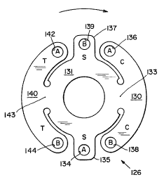
As shown in :Figure 4 the teachings of the
invention may be applied to a flexible coupling disc 126
which has two lobes 130 and 140 connected to an inner hub
or force transmission ring 131 by connector portions 133
and 143, respectively. Although a ring is shown as the
shape of hub 131 other shapes can be used, e.g. a diamond
shape, as long as the function of force transmission
between lobes is obtained. A third connector element is
provided in the form of lug portions 135 and 137; also
connected to the force transmission ring 131. Lobe 130
has bolt holes 136 and 13~ at its ends, and lobe 140 has
bolt holes 142 and 144 at its ends. Lug 135 is provided
with bolt hole 134 and lug 137 is provided with bolt hale
-11-
139. The connection of the flexible coupling is shown by
convention as being to driver shaft A and driven shaft B
by placement of the letters "A" and ''B" in the bolt holes
as shown in Figure 4. With the direction of rotation of
the coupling member being clockwise as indicated in
Figure 4, both ends of lobe 130 are placed in compression
and both ends of lobe 140 are placed in tension, The
lugs 135 arid 137 are placed in shear. Forces are thus
balanced out to obtain higher torque transmission, i.e.
the shear and tension forces in lobe 140 and lugs 135 and
137 balance out the compression forces in lobe 130 to
prevent column buckling.
To eliminate columnar loading entirely~an
intermediate coupling member can be used (as described in
more detail hereafter), which is illustrated in Figure 5.
Flexible coupling disc 126' has two lobes 130° and 140°,
which are connected by connector portions 133' and 143'
respectively to the inner force transmission ring 131'.
Lobe 130' is provided with bolt holes 136' and 138° at
its ends and lobe 140' is provided with bolt holes 142'
and 144' at its ends. Lugs 135' and 137' are provided
with bolt holes 134' and 139', respectively, and are
connected to an intermediate hub as shown by the
convention "I" placed in these bolt holes. By using an
intermediate hub member at least one flexible coupling
disc must be placed on each side of such intermediate hub
for connection respectively to the driving and to the
driven coupling member. Figure 5 shows a disc which has
both of its lobes 130' and 140° connected to the driving
member A, and another identical flexible coupling disc
will have both of its lobes connected to the driven
member B. These will be mounted on either side of the
intermediate hub member and the lugs 135° and 137' of
both of such discs would be affixed to the intermediate
hub. Such an arrangement increases torque transmission
still further since it is accomplished all in shear
~C~' ro ~ a~ rs
-12-
similar to a diaphragm type of coupling. Tt is the shear
forces generated at the connector portions 133' and 143'
which cause force transmission and the disc lobes are not
column loaded since they function essentially as "dead°'
elements. The use of the intermediate hub allows for
more misalignment, and misalignment conditions.
The connector portions and the central hub can
be combined in mechanical function by the use of a series
of connector bars as elements connecting the lobes. As
shown in Figure 6 a flexible coupling disc 226 is formed
with three lobes 230, 240 and 250 which are
interconnected by three connector bars 235, 245 and 255,
arranged in the form of a delta connection. In this
arrangement radial bending due to torque transmission is
eliminated. Obviously, other forms could be used, such
as a Y shape, or even only two bars being joined at one
lobe, or also a spoked type with bars joined at the
center. The lobes are provided with bolt holes 232, 242
and 252 for connection to a driving hub, and holes 234,
244, and 254 for connection to a driven hub. With
rotation in the counter-clockwise direction as shown in
Figure 6 each of the lobes will be in tension and
subjected to radial bending from torque. The bars
function as torsion beams due to actions caused by
angular and axial misalignment of the coupling hubs.
A preferred form of applicant's invention is
shown in Figures 7, 8 and 9 in which a flexible coupling
disc member 58 is used. As shown in Fig. 7 the disc 58
includes an inner hub portion 60, which is illustrated as
being essentially circular in shape. As indicated
previously the shape may be other forms such as for
example, triangular, without departing from the scope of
the invention. There are shown a plurality of
symmetrical outer lobes 62, 63 and 64, respectively
connected to the inner hub 60 via connector portions 65,
67 and 69. The lobe 62 has a pair of arms 75, 77 joined
.
x: ~,
l~~ ~ 'i i.l ~%
-13-
together adjacent the radial connector 65 and extending
away therefrom in opposite circumferential directions.
Similarly, the lobe 63 is provided with the arms 86, 87
adjacent the radial connector 67; and the lobe 64 is
provided with the arms 96, 97 adjacent the radial
connector 69. Each labs terminates in symmetrically
arranged arms provided with mounting holes for bolts.
Thus lobe 62 has belt hales 7~, 70' in arms 75, 77
respectively; lobe 63 has bolt hales 80, 80' in arms 86,
87 respectively; and lobe 64 has bolt holes 90, 90° in
arms 96, 97 respectively.
As will be seen in Figure 9 the discs 58 are
used in a plurality to form a disc pack. Each of these
discs may be relatively thin or thick, and are flat upon
assembly. They may be made of any appropriate similar or
dissimilar metallic or nonmetallic material. Also, as
seen in Figures 9 the disc pack 158 serves as an
intermediate coupling member (four individual flexible
discs being shown, although any number can be used) which
is bolted together between the first and second axially
arranged coupling members 74 and 76 (shown as slightly
misaligned 3n Figure 9).
As shown in Figure 8 the coupling member 74 is
formed with three spider-like arms 102, 104 and 106
extending from a central hub 100 which contains a bore to
accommodate the driver shaft 12. A set screw 82 is
employed to secure the coupling member 74 to the driving
shaft 112. In a similar manner, the driven coupling
member 76 is formed with three spider-like arms 202, 204
and 206 extending from a central hub 200 containing a
bore to accommodate the driven shaft 114. Bet screw 182
is provided to secure the coupling member 76 to the
driven shaft 114. Although not shown, keyways and keys
may be used in a well understood manner with the set
screws lacking onto the keys themselves. Also, although
a coupling member with "spider-like'° arms is shown, other
i~ -.
-14-
shapes, e.g. round, could be employed, while still coming
within the spirit and scope of the invention.
Figures 8 and 9 show the bolting arrangement.
A series of identical bolts 108 are used as described
hereafter. A bolt 108 secures the arm 87 of lobe 63 to
the arm 102 of the driving member 74 (as shown at the one
oarlock position of Figure 8). Another bolt 108 secures
the arm 75 of lobe 62 to the arm 104 of the driving
member 74 {as shown at the 9 o'clock position of Figure
8). Still another bolt 108 secures the arm 97 of lobe 64
to the arm 106 of the driving member 74. Similarly, the
arms 202, 204 and 206 of the driven member 76 are bolted
to the arms 77, 96 and 86 of the lobes 63, 62 and 64,
respectively. Thus, each lobe is attached to both the
Z5 driver and the driven coupling members and is flexed in
the process of being driven as shown in Figure 9.
Assuming a counter-clockwise direction Of
rotation as shown by the arrow in Figure 8, lobes 62, 63
and 64 are all placed tn tension because their respective
2,0 arms 75, 87 and 97 are being pulled by the respective
spider arms 104, 102 and 106. The respective connector
portions 65, 67 and 69 (see Figure 7) are placed in
shear. No columnar buckling can occur in this
arrangement. If a cloc7twise direction of rotation were
25 chosen in Figure 8, the lobes 62, 63 and 64 would all be
placed in compression because their respective arms 75,
87 and 97 are being pushed by the respective spider arms
104, 102 and 106. Fretting is inhibited due to the
effect of compressive forces on the substrate of the
30 material.
In the preferred embodiment of the invention an
intermediate hub is preferably used, as suggested lay the
discussion attendant with the description of Figure 5.
The arrangement is shown in the exploded perspective view
35 of Figure 10. A driving shaft 312 has mounted to it the
first coupling member 374, which has an outwardly
~~,~~'~~~f
3'J
-15-
extending hub 300 affixed to the shaft 312 by means of a
key and set screw in a well known manner. A series of
four (only three being seen in Figure 10) access holes
305 pass through the coupling member 374. Four bolts 308
are arranged to pass through the coupling member through
appropriate holes for fastening to a first disc pack 358.
A11 of the bolts are assembled by means of a spacer
washer 306 and nut 304: Each individual disc is formed
in the manner shown in Figure 7. although four such
discs are shown in Figure 10 for each disc pack, any
number can be used. Each disc may be separated from the
next one by means of a spacer (not shown). Disc pack 360
is constructed similar to disc pack 358. Three lobes
362, 363 and 364 are formed by the disc pack 358. Lobe
la 362 is formed with through holes 370 and 372 at the ends
of its arms; lobe 363 is formed with through holes 380
and 382 at the ends of its arms; arid lobe 364 is formed
with through holes 390 and 392 at the ends of its arms.
Holts 308 pass through the holes 392, 390, 380 and 382 to
fasten the lobes 363 and 364 to the driving coupling
member 374. The lobo 362 is fastened to an intermediate
hub 320. The hub 320 is generally square shaped and has
a central opening 330. Formed on the outer surface of
the hub 320 axe four bosses 322, 324, 326 and 328, each
of which has a through hole to receive a bolt 308. The
lobe 362 is fastened to the intermediate hub 320 by bolts
passing through bosses 324 and 326 and through the holes
372 and 370, respectively. Tn a similar manner the lobe
462 of disc pack 360 is fastened to the intermediate hub
320 by bolts 308 passing through the bosses 322 and 328 ,
and through the holes in the ends of the arms of lobe
462. The lobes 463 and 464 of the disc pack 360 are
fastened to the second coupling member 376 by means of
bolts 308 passing through holes 307 in member 376 and
through the appropriate holes in the lobes. The coupling
member is in turn fastened to a driven shaft 314.
~, 4Y
~,l [/~ ~ > ' J
>J i t3 fc4
-16-
Although only one intermediate hub is shown in this
preferred embodiment, a series of intermediate hubs
(associated with a series of flexible disc packs) may be
employed to accommodate greater misalignments.
~'ith the coupling device of the invention as
shown in Figure 10 employing an intermediate hub, the
disc packs function in the manner of a "wish-bone°°, i.e.
flexing occurs in the active inner ring portions adjacent
the lobes which are fastened to the intermediate hub.
ZO Fluxing in this manner greatly increases the flexing
length, resulting in lower side forces, greater angular
misalignment capability and predominately high axial
displacements. These are permitted without compromising
the torque transmitting ability of the device when
compared to convoluted diaphragm and disc coupling. In
Figures 5 and 12 the disc packs function in a manner of a
"double wish-bona flex". The lobes which are fastened to
the intermediate hub arc therefore either pulled or
pushed when the coupling device is in operation, and
their connector portions to the inner ring are subjected
to shear forces. The lobes which are fastened to the
driving or driven coupling member essentially are "dead'°
elements in 'the flex mode, but are a part of the torque
transmission system since both ends of each lobe are
fastened to the same member. 'there is essentially no
flexure in these lobes and they do not bend. There is by
this arrangement a greater ability to handle misalignment
and greater ability to transfer torque, because it is
handled in shear. Fretting action is eliminated as well
as fatigue problems at the bolts because there is no
bending of the arms of the lobes at the lobe end
attachment points. None of the lobes are subject to
column buckling.
Still other forms of discs may be used where an
intermediate hub is employed. For example, in Figure 11,
instead of an inner ring, the disc 558 is provided with
.a,
~~''~~~~i
-17-
an outer ring 560 having inwardly arranged lobes 562, 563
and 564. Lobes 562 and 563 are shown as being connected
to the driving coupling member while the lobe 564 is
connected t0 the intermediate hub. Companion discs or
disc packs on the other side of the intermediate hub
would have their lobes 562 and 563 connected to the
driven coupling member. Tn such a coupling device there
is no column buckling in the arms of the lobes, the
majority of the torque load is carried in shear at the
connecting portions of the lobes to the outer ring. 3n
Figure Z2 there are four lobes 662, 663, 664 and 665
shown as being connected to an inner torque reaction ring
660 in the disc 658. With lobes connected as shown to
the driving and the driven coupling members, the disc
functions as a solid hinged gimbal and large angular
misalignment is allowed. Where an intermediate hub is
employed two of the lobes (e.g. the lobes ~.ndicated as
being connected to ''B") would.be connected to the
intermediate hub, and another disc or disc pack would be
employed an the other side of 'the intermediate hub which
would have two opposed lobes connected to the driving
coupling member. This arrangement would allow for
parallel misalignment as wall as angular misalignment.
For maximum torque transmission, the inner hub opening
can be reduced to a small bore, to allow the solid
clamping (as by means of a bolt) of the flexible disc (or
disc pack) to the intermediate member. The attachment of
the flexible disc in this manner acts as a constraint on
plate buckling, which permits very high torque
transmission at very high transient and continuous forms
of misalignment. In still another arrangement a disc 758
could be employed as shown in Figure 13. The disc 758 is
formed with an outer torque reaction ring 760 and an
inner torque reaction ring 740. Three lobes 762, 763 and
764 are connected between the inner and outer rings.
When used with an intermediate hub the bolt connection is
%Y,
'3 7~ ~~ (~
~18-
as shown in Figure 13, it being understood that a similar
disc or disc pack would be located on the other side of
the intermediate hub and be connected to the B or driven
coupling member instead of the driving coupling member A.
Very high angular misalignment may be accommodated as
well as at very high torc~ues. The connector portions of
the label are subjected to double shear because of the
use of inner and outer torsion rings. The °'wishpbone"
flexing as above described occurs at both the inner and
outer ring connectians to the lobes.
It is clear that other arrangements of discs,
and different combinations employing intermediate hubs
may be employed, all within the spirit and scope of the
present invention. For example, in those configurations
which position the discs at the outside ands of the
coupling (i.e, with the driver and driven hubs adjacent
ane another), a part of the ring portions adjacent such
lobes may be eliminated so that the ring assumes a '°C"
shape, i.e., with open ends (the lobes may also be
shortened in length adjacent to the open part of the
"C"). This allows the disc pack to be readily removed
from the coupling device for easy replacement of discs
without having to disassemble the driving or driven
coupling member from the respective shafts to which they
are coupled. Obviously this could be done with discs
having an inner ring such as in Figs. 5, 7 and 12, an
outer ring such as in Fig. 11, or where both inner and
outer rings are used as in Fig. 13. Such a configuration
is showm for example in Fig. 11A, wherein the disc 558 is
provided with an outer ring 560, and an opening 559 is
provided by shortening the lobes 563 and 562, thus
forming the ring 560 into a "C°' shape.