Note: Descriptions are shown in the official language in which they were submitted.
2~28028
~xpress Mail LB143189563
t~nVdrYlbr~ trinslVptnt.~plcn
, Oc~ ~ 09:~:02 19~9
INTRINS ICALLY SAFE SYSTEM
Field Of The Inventio~
This invention relates to electrical systems,
such as instrument systems, which may operate in an
environment which may contain combustible materials. More
particularly, this invention relates to methods and
apparatus for ensuring that electrical energy and power
supplied to an environment which may contain combustible
materials are limited so as to minimize tne likelihood of
i~nition of comhustible materials.
BacXaround of the_Invention
Many loc~tions, such as in and around industrial
processes, ar2 or are subject to becoming "hazardous"
areas, i.e. areas in which the concentration of flammable
gases i8 or may become in the range which will present an
explosion and~or ~re hazard. Such hazardous areas often
require electrical apparatus and/or wiring to be present,
such as apparatus and wiring for instrumentation systems
to monitor and con~rol an lndustrial process.
~0 Several approaches have been developed to cope
with the explo6ion hazard in ~uch Areas. Initially,
apparatl~s was placed in heavy and expensive metal casings
and wiring was run in heavy and expensive metal conduit,
so that any axplosion ignited by ~he apparatus would be
~5 con1ned to the interlor of the hou~ing and conduit system
2~28~28
and unable to ignite hazardous atmospheres surrounding the
~ystem. Such "explosion proof" systems are extremely
expensive, and are inconvenient because they require that
the area be made non-hazardous prior to opening an
explosion proo~ housing such as to test, calibrate, or
inspect apparatus in the housing.
With the advent of solid state electronics, it
became possible to design instrumentation and control
systems operable at power levels low enough to be
intrinsically unable to ignite specified hazardous
atmospheres. So long as the energy storage capacity of
circuits supplied from energy and power limited supplies
is sufficiently low, such apparatus will be incapable of
releasing sufficient energy to ignite hazardous
atmospheres and the entire system, including both wiring
and connect~d electrical apparatus, will be safe for u~e
in the hazardous atmosphere.
Since all real~world 3ystems are s~bject to
component ailure, systems are generally desi~ned to
tolerate B certain number of events which are considered
to be faults in the system, while still maintai~ing energy
and power lavals su~ficiently low as to preclude ignition
of a hazardous atmosphere. According to generally
accepted standards, a ~ystem i~ deemed "intrinsically
safeN for a ~peciied hazardous atmosphPre if it can
withstand any combination of two ~aults in tha ~y~tem
while maintaining en~rgy and power levels below the limits
necessary to ignita that ha~ardous atmosphere.
2028028
Intrinsic ~afety "barriers" have been developed
to prevent intrusion of hazardous voltages and currents
into circuitry which is intended to be intrinsically safe.
Such barriers have an input terminal adapted to be coupled
to a power ~ource, an output terminal adapted to be
coupled to intrinsically safe wiring and circuity, means
for limiting the voltage which may be applied to the
output terminal, and means for limiting the current which
may be supplied to the output terminal. Such barr~ers
typically include a fuse to protect the voltage an~
current limiting components from ~ailure in the event of
high power being supplied to the input terminal.
Such barriers generally c~ntain components whose
failure modes, arrangement, and redundancy are such that
the output terminal is considered intrinsically safe. The
circuit components and terminals are typically supplied as
a potted or encapsulated assembly in which the components,
including the fuse, are inaccessibl~. By supplying one
such barrier in eac~ non-grounded line entering a
20 hazardous area, those lines will be rendered intrinsically
~afe provided that intrinsically ~afe wiring practices are
followed and devices coupled to those lines have
appropriately low ener~y storage capacity.
However, ~uch intrinsic ~afety barriers are
expen~ive items, and can considerably afect the cost of
an intrinsically safe circuit or system. This i5
particularly the case with systems involving a large
number of intrinsically safe circuits. Moreover, when a
fault cccur8 which blows a fuse in a barrier, it typically
-4-
must be replaced, leading to additional expense and
inconvenience. Some intrinsic saf2ty barriers also laçk
the ability to have each limiting component tested
individually to verify that the barri~r is fully
unctional with t~e intended degree of redundancy. Even
in barriers whera quch tests may be made, testing
typically requires removal of the barrier from service, a
procedure which may involve considerable expense, time,
and inconvenienc~.
S mmarv Of The Invention
It it therefore an object of the invention to
provide inexpensive intrinsic safety means.
It is a further object of the invention to
provide intrinsic sa~ety means suitable for use with a
lar~e number of circuits.
It is another ob;ect of the invention to provid~
intrinsic sa~ety means usable with a wide variety of ~ield
devices.
It i3 another object o~ the invention to provide
intrinsic sa~ety means using only passive components in
the ~ntrinsically sa~e lines.
It ~s ~nother object o~ the invention to provide
intrinsic safety means which does not degrade a ~ignal
~asslng through ~t.
- 2~28~28
It is another object of the invention to provide
intrinsic safety means which permits great separation
between the electrical supply and hazardous area equipment
it supplies.
It is anoth~r object sf the invention to provide
intrinsic safety means which is simple and convenient.
It is another object of the invention to provide
intrinsic safety means which may be tested without removal
from service and without interruption in operation of the
circuits protected by the intrinsic safety means.
In accordance with the foregoing objects, the
intrinsic &afety means of the present invention includes a
plurality of lntrinsically afe conductors each of which
is coupled to a common power supply, current limiting
me~ns associated with each intrinsically safe conductor,
and voltage limiting means coupled to and effecti~e to
limit the voltage o~ the common ~upply. In accordance
with the pr~ferred embodiment o~ the invention, the
voltage limiting means comprises redundant crowbar
circuits.
These and other objects and features of the
inv~ntion will b~ understood wi~h re~erence ~o the
~ollowing description, the drawings, and th~ claims.
2~2~2~
Briaf Description_of the Drawinqs
Figure l is a schematic diagram of an intrinsic
~afety barrier typical of the prior art.
Figure 2 is a block diagram o a typical
intrinsically sae system according to the prior art.
Figure 3 is a block diagram of an intrinsically
safe system in accordance with the present invention.
Figures 3a and 3b show preferred current interrupting
means and current limiting means, respectively, for use in the
present invention.
Figure 4 is a schematic diagram of a crowbar
circuit useul in the system o~ the present invention.
Figure 5 is a ~lock diagram of an Pmbodiment of
2~ the invention which includes means for testing certain
protective components.
Detailed~DescriptiQ~ of the Preferred Embodiment
Figure 1 shows a schematic representation of an
intrinsic ~afety barrier used in accordance with the prior
art to protect a ~lngle line lntended to ~e run in a
hazardous area. The barrier includes an input terminal 24
intended t~ be coupled to a source of power and an output
terminal 26 intended to be coupled to ~azardous area
wirin~ ~nd circuitry. The barrler includes redundant
zener diodes 20 and ~2 ~or limiting the ~oltage which may
be presented to output terminal ~ upon t~e occurrence o~
fault conditions, ~uch as excessive voltage and/or
current, at lnput terminal 24. Re~lstQr 18 i~ prov ded to
2~28~28
limit the maximum current available through output
terminal 26. Fuse 14 is provided to disconnect the output
and th~ protective circuitry of the barrier from the input
upon high input current conditions to the barrier, and
resistors 12 and 16 are provided to limit the current and
hence the dissipation in zener diodes 20 and 22 under
~ault ~onditions in the time interval before fuse 14
blows. The barrier includes redundant connection~ 28 and
30 adapted to be coupled to an intrinsically safe ground,
which in accordance with intrinsic safety wiring practices
is requ~red to be connected to a ~acility's central
grounding location by redundant protected wiring having
resistance of one ohm or less. The components of the
intrinsic safety barrier, including ~u~e 14, are
gener~lly potted or encapsulated to preclude intentional
or accidental actions which may affect the ability of the
barrier to maintain its output terminal intrinsically
~afe. Accordingly, an input fault condition generally
requires replacement o~ the entire barrier, an ~xpensive
and inconvenient procedure. Moreover, because resistor 18
i5 reguired to limit the output current available when the
maximum voltage is present acros~ zener diode 22 under
fault conditions, the additional r~sistance o resistors
12 and 16 r~duces the resistance which may be allocated to
field wiring or ~ield devices und~r normal operating
conditions. Thi~ may, for instance, und~lly limit the
conductor length and physlcal separation ketwe~n the
barrier and 3 connected field device.
Figure 2 ~how~ a typical prior art ~ystem
providing intrin~ically ~a~e circuitry in a ha~ardous
2~28~8
--8--
area. A plurality of field devices 46a, 46b ... 46n are
required to be plac~d in a hazardous area ancl supplied
with power over lines 44a, 44b, ... 46n. Such field
devices may include transmitters, transducers, indicators,
and the like. Typically, such field devices will be
required to be placed in a hazardous area in order to
monitor or control the ~tatus of processes and materials
in the hazardous area. Often such ~ield devices will be
transducers or other devices operating in a 4-20 mA two-
wire loop, i~ which event the lines 44 would eachcorrespond to one conductor of each such loop. The oth~r
co~ductor o such two-wire loops may be coupled to a
barrier-protected line or to an intrinsically safe ground.
Field devices 46 in the hazardous area are
generally supplied with power from circuitry in a non-
hazardous area. Such circuitry will ~enerally include a
power supply 40, generally an AC line-powerPd supply of
approxi~ately 24 volts DC output. Supply 4Q generally
energizes certain circuitry coupled to the conductors or
lines 44 and designated in Figure 2 as function block 42.
Function block 42 may comprise signal generating,
monitoring, or measuring devices, displ~y device~,
multiplexing circuits, and/or a variety of other devices
performing disparate ~unctions xelating to t~e ~ield
devices. As shown in Eigure 2, a single ~nCtiQn block 42
is illu~trated w~ich is coupled to all field devices and
power supply co~mon; it will be under~tood that one or
more functional blocks may ~e dedicated to eac~ ld
device ~6 and associated line 44.
2 ~ 2 ~
In order to protect lines 44a, 44b, ... 44n and
their associated field devic~s 46a, 46b, ... 44n from
intrusion of hazardous energy upon fault conditions in the
non-hazardous area or in the hazardous area, intrinsic
safety barriers 48a, 4~b, ... 48n are provided. Each such
barrier 48 may have the structure shown in Figure l; other
designs, however, are in use. Barriers are provided in
each non-grounded line entering the hazardous area.
Accordingly, conventional two-wire signal 10QPS require
two barriers per loop. For circuits in which one
conductor is coupled to the intrinsically safe ground,
only one barrier per loop is needed. However, this can
still result in considerable ~xpense and inconvenience
which the present inve~tion is intended to avoid.
Power ~upply 40 may be coupled to other or
auxiliary clrcuitry 50 which ls not coupled to or related
to the field devic~s. In the system of Figure 2, barriers
48 do not protect or otherwise af~ect such circuitry.
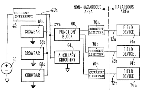
Fi~ure 3 shows an intrinsically ~afe system
according to the preerred embodiment o~ the lnvention.
Like the ~ystem o Figur~ 2, the 6ystem of Figure 3
includes a plurality o fi~ld devices 74a, 74~, ... 74n
which may be located in a hazardous area and w~ich are to
be supplied with electrical energy over conductors or
~5 lines 7~a, 72b ... 72n. As pr~vio~sly described, such
ield devices may include indicators, tra~sducer~,
tra~smlt~erfi including ~-20 mA tr~nsmitter~J ~nd the like.
Power for the ~ield devices ~4 i8 derived ~rom power
~upply 60 g~nerally loea~ed in the non-hazardous area.
2028~28
--10--
Power supply 60, like that of Figur~ 2, is generally an AC
line powered supply having an output on the order of 24
volts DC. Shown coupled to power supply 60 by supply line
67a, 67b is function block 66 which, like function block
42 described above with respect to Figure 2, may comprise
signal generating, monitoring, or measuring devices,
display devices, multiplexing circuits, or a variety of
circuits performing other functions. In general, function
block 66 comprises the functional interface between the
~ield devices and the equipment in the non-hazardous ~rea,
and the means by which power is coupled to lines 72 and
thus to field devices 74. It will be understood that
while a ~ingle function block is shown in Figure 3,
e~uivalently a plurality of function blocks could be
provided each o~ which serves one ~r more lines and field
devices. It will further be understGod that systems in
accordance with the invention n~ed not include means for
providin~ any f~nction in function block 66 other than
coupling power to the field circuit.
~0 The supply line coupling current interrupting
means 62 to function block 66 and auxiliary circuitry 64
1~ identified in one portion as 67a and in another as 67b,
to enable comparison o~ corresponding circuit portions in
the d2scrip~.ion of Figure 5. The diff~rentiation is not
fiigniicant i~ Figure 3, and both portions will be
re~erred to collectively as supply line 67.
In accordance with the invention, at least one
crowb~r circuit is pro~ided between he ~upply llne 67 and
a conductor coupl~d to intri~sicalLy ~a~e ~round. By
2~28~28
--11--
providing such a crowbar circuit, supply line 67 is
rendered a voltage limited conductor and the power supply
means coupled to function block 66 is rendered a voltage
limited power supply means. Preferably, and as shown in
Figure 3, a plurality of such crowbar circuits is
provided. In Figure 3, three such crowbar circuits 68a,
68b, and 68c are provided, each of which may be identical.
Such crowbar circuits sense the voltage of the protected
supply line 67 and, if it exceeds a predetermined
threshold, such as 28 volts, provide a low impedance path
between the protected supply line and intrinsically safe
ground.
In accordance with the preferred embodiment of
the invention, a current interrupting means 6~ such as a
fuse is provided in the power supply linP between supply
60 and function block 66 to current limit supply line 67.
Other current interrupting means, ~uch as a circuit
breaker, may also be used. Figure 3a shows fuse 63 which is the
pre~erred current interrupting means 62 of the present invention.
Accordingly, in the circuit of Figure 3, the
protected supply line 67, so long as it is prokected from
intrusion of hazardous energy or power levels which bypass
current interrupting means 62, forms a fail-safe supply
which is voltage limited with respect to intrinsically
~afe ground. In the event of an overvoltage and/or
overcurrent co~dition at power supply 60, ~uch as may be
cau~ed by a shorted pass transi tor in power ~upply 60,
the voltage on line 67 will ri~e to the thresh~ld voltage
of crowbar circuits 68a, ~8b, and/or 68c. Even if two
crowbar circuits 6~ are ~aulted and non~unckional, at
~828~
least one will be functional to impose a low impedance
path to ground and to limit the voltage on line 67 to non-
hazardous levels. In most circumstances, this will cause
current interrupting means 62 to open, there~y removing
power ~rom function block 66, from the ~ield wiring and
devices, and from the crowbar circuits. So long as the
short circuit current capacity o the crowbar circuit~s)
is greater than the current required to open current
interrupting means 62 and their short circuit impedance is
sufficiently low, and the resistanc~ of the electrical
return path to power supply 60 is low, the voltage on line
67 will be maintained at intrinsically safe lsvels even
with input overvoltage and/or overcurrent fault conditions
and two aulted crowbar circuits.
By providing intrinsically safe voltage limiting
to the lines supplying power to the field wirin~ and field
devices, such wiring and devices may ~e made intrinsically
~afe by limiting the current which may be introduced into
them. Thi5 i8 easily accomplished by provision o~ current
limiting means 70a, 70b,...70n, in each line 72a, 7~b,...72n, Such
current lim~t~rs are desirably of a construction which, if
they fail, will fail safely, i.e. which in this
application will ~ail to an open circuit or high impedance
condition rathe~ than a short circuit or low impedance
condition. Figure 3b shows a resistor 65 which is the preferred
current limiting means 70 of the present invention. Metal film and
wirewound resistors are suitable. Use of passi~e components such
as resistors for current limiting minimizes the likelihood of
failure and, in particular, low-impedance failure. Moreover, such
passive components minimize any signal degradation in the current
limiting means.
~2~02~
It will be noted that any field line and field
device may be protected by simply including an inexpensive
resistor ~n series with the line. Thus, by en~urlng that
the power supplies which may be coupled to the field
wiring are appropriately voltage limited, any number o~
field circuits may be rendered intrinsically safe by the
~imple and inexpensive inclusion of a resistor in the
line. This is particularly advantageous 1~ systems
supplying large numbers of field circuits. Of course, it
will be understood that ordinary intrinsic safety
considerations will apply to the system of Figure 3, such
as limitation of the energy storage capability of the
lines 72 and field devices 74 and use of intrinsically
safe wiring practices.
Since no resistan~e is provided to limit the
current in crowbar circuits 68, other than the internal
resistances of the sourc~ 60, wiring, current interrupting
means 62, and the crowbar circuits them elves, the
parasitic e~fect~ o~ such resi~tance, described above with
re3pect to intrinsic ~aety barrier resistances 12 and 16~
are avoided. Thus the system of the ~nvention maximizes
the re istance available ~or ~ield wirin~ and devices and
thu~ the separation whlc~ may be obtained under given
conditions between the field device~ 74 and the non-
ha~ardous area circuitry.
Eigure 3 further ~hows auxiliary circuitry S4couplad to power ~upply 60. In ac~ordance with the
invantion, other non-ha~ardous-area circuitry be~ides the
function block 66 as~ociated with the ield devices may be
supplied from power supply 60. In the ev~nt that it is
desired that such circuitry be protected from overvoltage
conditions, such circuitry may be operated from the
protected supply line 67, as shown.
Figure 4 shows crowbar circuitry useful in
connection with the present invention. It will be
understood, however, that many crowbar circuits including
the circuit o~ Figure 4 are known per se and may be used
in the system o~ the present invention.
The shorting element of the erowbar circuit of
Figure 4 is silicon controlled rectifier (SCR) 80,
connected with its main terminals coupled to intrinsically
safe ground and to the protected supply line S7. SCR 80
is controlled by o~rvoltage sen~e circuit 82 which may be
Motorola type MC 3423, an integrated circuit (IC~
speci~ically designed for use in crowbar circuits. IC 82
sourc~s current from pin 8 when the volta~e applied to pin
2 exceeds an internal reference vol~age. Accordingly,
resistors 84 and 86 form a voltage divider to establish
the voltage o conductor 67 which, when axceeded, will
cause current flow out o~ pin 8. Such current ~low
provides gate current e~fective to ~ire SCR 80 and thus to
crowbar the ~upply. Resistor 88 i8 provided to limit the
gate curr~nt of SCR 80, and resis~or 90 bypasses leakage
current. Capacitors g2 and 94 are provided for noise
immu~ity so that brief noise transients do not actuat~ th~
rrowbar and diRable the system. Zener diode 96 is
provided to protect IC ~2 from supply overvoltage
~2~
conditions, and may assist in causing the supply fuse to
open in the event o input overvoltage conditions.
It will be understood that other crowbar
circuits may be employed in the system of the invention,
which may involve means ~or imposing a low-impedance path
other than an SCR, such as a triac or a diac.
Figure 5 shows a modification of a portion of
the system of Figure 3 to permit testing and verification
of operability of the crowbar circuits. The system of
Figure 5 includes means ~or such testing and verification
which may take place without interruption of the normal
functioning of field devices 74, auxiliary circuitry 64,
or devices comprising function block 66 of Figure 3, and
without affecting the intrinsic ~afety affordad by the
system. In order to provide for such testing, testing
circuitry including pass element 100, control circuit 10
and switch means 116a-c i8 provided. To permit ac~uation
of the crowbar circuit~ during testing without opening
current interrupting means 62, which would disable the
sy~tem, pass element 100 is insarted in series with
conductor 67. Pass element 100 controls current ~low
between conductor 67a, connected to the current
interrupting ~e~n~ and conductor 106, under th~ control of
control line 126. Pass element 100 may comprise a
~5 transistor coupled to control line 126. Load , such as
function block 66 and auxiliary circuitry 6~ of Figure 3,
are co~pled to conduct~r 67b.
~28~8
-16-
Crowbar circuits useful in t~e present inYention
will generally include means ~or comparing a signal
related to the monitored voltage with a threshold value,
and for actuating a ~witch in response to the comparison.
Such features render the crowbar circuits amenable to
testing without the necessity of raising the monitored
voltage to a level above the normal threshold voltage of
the crowbar circuits. While crowbar circuits could be
tested in this fashion, doing 50 greatly oomplicates
testing of the individual crowbar circuits; if the voltag~
o~ the monitored conductor were merely rai~ed, the crowbar
circuit having the lowest threshold voltage would b
actuated first and prevent actuation of the other crowbar
circuits.
The system of Figure 5 avoids such difficulties
by simulating oYervoltage conditions at each crowbar
circuit. Such conditions may be simulated separately for
each of the crowbar circuits present, en~bling tham to be
individually tested. In the ~ystem of Fisure 5, each of
the crowbar circuits 6Ra~ b, and c includ~s an input 114a,
b, and c to which a ~ignal may be applied to establi~h,
control, or vary the threshold at which the crowbar
circuit will ~e actuated. Testing of the crowbar circuits
in Eigure S in carried out under the control of control
circuit 102. Control c~rcuit 10~ may include means ~or
initiat~ng a test, such a~ timer means ~or automatically
initiating a test. Co~trol circuit 102 also may lnitiate
a te~t i~ respon~ to an input 130 such as may b~ supplied
~rom an operator, external ~ircuitry, or- the like.
g ~2~8
-17-
The testing sy~tem of Figure 5 includes means
for varying the inputs 114 of the crowbar circuits 68. In
the system of Figure 5, means for varying the imputs
comprises switches 116a, b, and c, which are controlled by
control circuit 102. In the normal position, as shown,
switches 116 couple the inputs 114 of crowbar circuits 68
to conductor 120, which establishes ~or the crowbar
circuits the normal threshold voltage to provide
intrinsically safe operation, such as 28 volts on
monitored conductor 106. In normal operation, control
circuit 102 al60 controls pass element 100 so that current
through it i8 ~ssentially ~nrestricted, such as by causing
saturation of a pa~s transistor in pass element 100.
To perform a test, the current capacity of pass
element 100 is controlled by control circuit 102 to be
less than the current which would open circuit
interruption ~eans 62. Control circuit 102 then causes
actuation of the switch means 116 coupled to the
particular crowbar circuit to be tested, thereby coupling
the corresponding control input 114 to co~ductor 122.
Thi~ e~tablishes a monitored voltage threshold for
actuation of the crowbar circuit 6~ to be tested which is
less than the voltage noxmally ~upplied by supply 60 or
present on conductors 67 or 106. If the erowbar circuit
under test is unctional, the ~resence of a monitored
voltage highar than itB threshold voltage will cause it to
impose a low-impedanca path across the crowbar circuit,
1.e. between conductor 106 and intrinsically Ba~e ground.
This in turn will cause a drop in the voltage of conductor
105 which may be detected to indicate that the crowbar
202~02~
-18-
circuit has been actuated. Detector 104 in the circuit of
Figure 5 is a means for providing a signal to control
circuit 102 which is responsive to actuation of a crowbar
circuit, in the embodiment shown by responding to the
change in voltage of monitored conductor 106. As shown,
detector 104 detects the voltage of conductor 106 with
respect to the voltage of conductor 67, i.e., it is
responsive to the voltage across pass element 100.
However, it will be understood that detector 104 may
equivalently be responsive to the voltage o conductor 106
with respect to the other potentials, or may even s~nse
the actuation of a crowbar circuit by other effects, such
as by detecting the current or change in current through a
crowbar circuit.
Actuation of crowbar circuit under the testing
conditions described above will generally cause conductor
106 to be effectively grounded, or at least unable to
support the load imposed by field devices, auxiliary
~ircuitry, and the like coupled to conductor 67b. Diode
108 ~nd c~pacitor 112 provide a means for continuing to
supply power to such connected loads during te~ting of the
crowbar circuits. Capacitor ll~ will be charged during
normal system operation, and if it~ capacitance is
~ufficiently large considering the load and the duration
o the testing procedure, it will maintain the voltage o~
~onductox 67b ~ufficiently hi~h to permit continued ~ystem
opera~ion durin~ ~estins. Diode 108 i~ a means for
preventing di~charge o~ c~pacitor 112 by ~he crowbar
circuits. Diode 108 and capacitor 11~ in efect ~orm a
backup power supply which act~ au~omat~cally to power the
~go2~
-19--
load during testing of the crowbar circuits. Accordingly,
it will be understood that other means may be provided to
perform this ~unction, such as a separate power supply to
which the load is switched during testing of the crowbar
circu~ts.
Crowbar circuits useful in the present invention
include circuits in which the low impedance path imposed
upon actuation may per ist after the condition which
actuated them. The crowbar circuit of Figure 4 operates
in this fashion; once triggered, ~CR 80 will remain on
until the current through it is reduced substantially to
zero. For ~uch circuits, control circuit 102 may include
means for controlling pass element 100 so as to decrease
its curre~t conduction below the holding current of a
crowbar circuit 60 and p~rmit it to reset. Such means may
be employed upon rec~ipt by control circuit 102 of a
si~nal indicating that a crowbar circuit has been actuated
in response to a test. Thereafter, control circuit 102
causes pass element 100 to assume its normal conduction
~0 state, allowing power supply 60 to recharge capacitor 112
and support the connected load on conductor 67b. It will
be understood that other ~eans for resetting latched
crowbar circuits may be provided which are appropriate for
the particular crowbar circuit6 employed.
2S In the event that detector 104 does not indicate
to control circuit 102 that 9 crowbar circuit has been
actuated within a predetermined ~ime after a crowbar
circult test has been initiated, the crowbar circuit under
2~2802~
-20-
test may be deemed to be faulted and the test may be
texminated.
Test circuit 102 may comprise means for
generating an output 132 in response to the results of
testing. Such an output may inclu~e a visual display, a
signal ~or communication to other circuitry, or the like.
The foregoing testing procedure may be performed
~eparately for each o the crowbar circuits pr~sent in the
~ystem, enabling separate testing and identification of
any faulted crowbar circuits. Testing may be performed
automatically and repetitively to provide continued
assurance of intrinsically ~afe conditions, or whenever a
verification of such conditions is desired.
Accordingly, systems have been disclosed which
are capable o~ ~imply, reliably, and inexpensively
rendering a plurallty o circuits intrin~ically safe.
While particular methods and apparatus have been
described, it will be understood that variations will no
doubt occur to those skilled in the art without departing
from the spirit of the invention.