Note: Descriptions are shown in the official language in which they were submitted.
,..~; t ~'J ~, ~,3 ~ ~ i
A fluidized bed apparatu6 for making and/or processing
pourable material~
The invention relates to a fluidized bed apparatus for making
and/or processing pourable material consisting of solid molded
parts, comprising
- at least one treatment chamber which includes at least one
gas inlet and at lea~t one gas outlet to produce a general
~low of gas,
- at least one hollow lance extending transversely of the
general flow of gas in the treatment chamber, having an out-
line which is symmetrical with r~spect to a center plane, and
including a conveyor channel which extends in longitudinal
direction of the lance and to which discharge nozzles for ma-
terial are connected, and
- at least one pair of guide vanes between which the lance is
arranged for the general flow of gas to flow around it ~rom
the bottom to the top~
In the case of a fluidized bed apparatu~ of thi~ kind known
from DE 38 39 723 Cl the treatment chamber is the circular in-
ner space of a vessel which is rotationally ~ymmetrical with
respect ts a vertical axis. In the treatment chamber there is
a ring of guide vanes which overlap one another, as seen in
the direction of the axis o~ the vessel, to give a twist or
spin to the upwardly direGted flow o~ gas. Lance~ disposed ra
dially with respect to the axis of the veesel are arranged
between the guide vanes. They ea~h include a plurality of
discharge nozzles ~o deliver ma~erial which are located in the
direction of flow of the gas. Great quantities of pulverous
and~or liquid material can be supplied through ~hese nozzles
per unit time into a fluidized bed which forms above the guide
vanes~
L Granular material which has been produced and/or processQd in
this known fluidized bed apparatus is characterized by excep
tionally good homogeneity. For instance, in making nucleating
granules, ~ narrow particle size spectrum can be achieved and,
in coating, the layers of coat obtained are of particularly
uniform thickness.
Such unifo~mness, however, is not alway~ desirable. To fill
capsules for pharmaceutical application, for example, some-
times pellets are n~eded that have coat~ of different composi-
tions or di~ferent thicknesses in order that certain active
substances may be relea~ed specifically in certain areas of
the human gastrointestinal tract. Up to now, such different
pellets had to be produced in batches one after the other in
the known apparatus, and longer shutdown periods could not be
avoided to adapt the machinery to different operating condi-
tions. At a given contain~r size, the batch quantity o~ the
known apparatus can be varied within relatively narrow limits
only so that production by means of such fluidized bed appara-
tus cannot readily be changed to conform to different opera-
tional requirements.
It is, therefore, the object of the invention to devise a
fluidized bed apparatus for producing and/or processing pour-
able material consisting of solid molded parts so that the ap-
paratus i5 easily adaptable to dif~erent requirements of the
kind mentioned.
Starting from a ~luidized bed apparatus of the kind described
initially, the object is met, in accordance with the inven-
tion, in that
- the center plane of the lance i~ located at least approxi-
mately vertically,
- a pair of semishells are disposed above the guide vanes
forming, together with the guide vanes, a straight trough
which is at least approximately symmetrical with respect to
the center plane, and
- a pressure gradient can be produced be~ween the gas inlet
and the gas outlet, at which gradient a rectilinear fluidized
bed is formed within the trough.
3 ,1 I J 1~1 ~'iJ 13 ~ ~
A trough according to the invention of a given overall length
can constitute a single rectilinear treatment path in a corr~-
sponding elongated housing, or it may ~e subdivided in~o a
plurality of sections which can be arranged in space-sa~ing
manner side by side in a common housing. In any case, similar
or dif~erent steps of treatment may be performed at the same
time in more or less long sections of the trough, as may be
required, while unused sectlons are shutdown, for example by
the provision of partitions. It is likewise possible to set
out with dif~erent starting materials, such as pellets, cry-
stals, tablets, or granular material of different composition
and/or size supplied to different sections of the trough
which, for instance, may be positioned side by side so as to
obtain a final product in the end which will have a certain
mixture of different particles.
Advantageous further developments of the invention may be ta-
ken from the subclaims.
Embodiments of fluidized bed apparatus according to the inven-
tion will be described further below with reference to the ac-
companying diagrammatic drawings, in which:
ig. 1 is a longitudinal sectional elevation in the vertical
plane I~I of fig. 3 of an apparatus for coating and
drying prefabricated molded parts;
Fig. 2 is an enlarged cutout of fig. 1;
Fig. 3 is the vertical cros~ section III-III of fig. l;
Fig. 4 is the top plan view in the direction of arrow IV in
~ig. l;
Fig. 5 is the top plan view o~ an apparatus for extruding,
coating, and drying molded parts;
Fig. 6 is the longitudinal section VI-VI of fig. 5;
Fig. 7 is the cross section VII-VII of fig. 5;
Fig. 8 is a much enlarged cutout o~ fig~ 7;
Fig. 9 is the corresponding side elevational view, shown
partly as s~ctional view IX-IX of fig. 8.
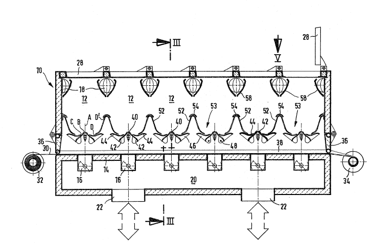
Th~ fluidized bed apparatus illustrated in figs. 1 to 4 com-
prises a housing 10 which presents a parallelepiped of ~lon-
gated configuration in horizontal direction and has thermally
insulated walls. Six treatment chamb~rs 12 are formed inside
the housing 10, having a common bottom 14, two gas inlets 16
each located in the bottom, and gas outlets 18 of which five
each are associated with two adjacent treatment chambers 12.
Through the gas inlets 16, the treatment chambers 12 communi-
cate with a common air supply chamber 20 disposed under the
bottom 14 and receiving dehumidified hot air or another gas
for treatment through connections 22. The gas outlets 18 open
into spent air chambers 24 arranged at the longitudinal sides
of the housing 10 and extending down to below the bottom 14
where they are adapted to be connected to the suction end of a
conventional blower through connections 26. In operation, each
treatment chamber 12 is closed at the top by a lid 2B made,
for example, of glass and adapted to be swung open for clean-
ing purposes.
conveyor belt 30 permeable to gas, ~uch as a known ar~icu-
lated or jointed band o~ metal or plastics wire helices, lies
on the bottom 14 and extends in longitudinal direction through
the entire housing 10. The conveyor belt 30 may be wi~hdrawn
from a pay-off reel 32 and wound up, after use, on a take-up
reel 34. Instead o~ these two reels 32 and 34, deflecting pul-
leys may be provided around which an endless conveyor belt is
passed.~The face e~ds at whi~h the conveyor belt 30 enters
into and leaves the housing 10 normally are closed ~y a flap
3~ each.
To empty the treatment chambers 12, it is proYided to place a
foil 38 on a section of the conveyor belt 30 which is somswhat
longer than the housing 10. By moving the conveyor belt 30,
this foil subsequently is brought into the housing 10, loaded
with material made or processed in the treatment chambers 12,
and then moved out of the housing 10 together with ~hat ma-
terial by renewed movement o~ the conveyor belt 30. ~s indi-
cated in fig. 1, the foil 38 is drawn upwardly to 8uch an ~x-
tent at the lateral limits of the treatment chambers 1~ that
any contamination of the conveyor belt 30 by the ~omposition
being produced and~or treated i5 avoided.
All the built-in structures which will be described below are
symmetrical with respect to a vertical center plane A of the
respective treatment chamber 12, which plane extends trans-
versely of the longitudinal direction of the housing lo. A
lance 40 passes horizontally and spaced above the bottom 14
through each treatment chamber 12 in the center plane A. The
outline of each lance 40 is of drop shape, symmetrical with
respect to the center plane A, being rounded at the bottom and
pointed at the top. At both sides of this contour there are
two guide vanes 42 and 44 each, disposed in parallel with the
corresponding lance ~0.
~he two guide vanes 42 and 44 at one and the other side of the
lance 40 are interconnected by plates 46, e~ch extendiny in a
vertical longitudinal plane and fastened on a shaft 48 which
extends parallel to the lance 40. The shafts 48 are connected
to a pivot drive means 50 each, for example an hydraulic or
pneumatic rotary wing motor by means of which the associated
guide vanes 42 and 44 are pivotable back and forth through an
angular range o 30, for instance.
A semishell 52 each is arranged at either eide o~ the lance
40, llkewise extending parallel to the same. Together with the
corresponding guide vanes 42 and 44 an~ the lance 40, the se-
mishells 52 fo~m a trough 53 which is almo&t totally closed at
the bottom when the guide vanes are in their operating posi-
tion - cf. second and third treatment chambers 12 from the
right in fig. 2 but leaves open threa gaps B, C, and D at
either side of the lance 40. These gaps extend throughout the
width of the treatment chamber 12. Air used in th~ treatment,
in the form a general ~low of gas E (cf. figs. 2 and 3) may
flow through these gaps B, C, and D, starting from the cor-
6 ,',1 1~ f'/ ~ ,J 9i,,~
responding gas inlets 16 and flowing around the lance 40 inupward direction, forming a fluidized bed F which is defined
by the trough 53 (cf. second chamber from the right in ~ig. 2
and fig. 3).
The guide vanes 42 and 44 can be pivoted by the pivot drive
means 50 from their operating position into an emptying posi-
tion - cf. first chamber from the right in fig. 2. In this po-
sition, the material which has accumulated in the trough 53
after shutdown of the air flow may trickle down through the
gaps B, C, and D on to the foil 38.
An intermediate ~pace is left free between the upper edges of
the semishells 52 in adjacent treatment chambers 12, and this
space is covered by a roof element or shaped cover 54 which is
concave when looked at from below. Between the upper edge of
each semishell 52 and the corresponding shaped cover 54 a gap
D' is left open through which another part of the general flow
of gas E flows from top to bottom into the respective trough
53. The shaped covers 54 are mounted in such a way that mate-
rial may flow across them if it exceeds a certain level in one
of the troughs 53. A~ an alternative, adjacent troughs 53 may
be separated by a partition 56. The gas outlets 1~ located at
a highex level are covered by baffle pla~es 58 so that dust~
like particles, at best, of the composition will get into the
spent air chambers 2~ where they can be ~eparated in known
manner from the gas ætream by filtering.
In all its treatment chambers 12, the apparatus shown in figs.
1 to 4, is fit for fluidized bed coating and drying of prefa-
bricated molded parts P, such as pellets or tablets which are
poured ~rom above into each individual trough 53. With ~he ap-
paratus according to figs. 5 to ~, on the other hand, it is
possible irst to extrude particles o~ a doughy mass, and then
coat and finally dry them. Consequently, as the field o~ use
of the apparatus illu~trated in figs. S to 9, begins at an
earlier stage of the manufacturing process, details of this
7 ~ s; . 1 i3 ~i ~
apparatus will be described below before dealing with furth r
common features of both apparatus.
.
As shown in figs. 5 to 7, three elongated treatment chambers
12 corresponding to those illustrated in figs, 1 tD 4 are ar-
ranged one behind the other in the housing 10, The left one in
fig~. 5 and 6 of these three treatment chambers 12 serves for
extruding, the central one for coating, and the right one for
drying. A single lance 40 subdivided into three aligned sec-
tions, one for each treatment chamber 12, extends through the
three treatment chambers 1~. Thrsughout their lengths all the
portions of the lance 40 have the out~r contour shown in fig.
7, whereas only the part in the left treatment chamber 12 has
all the design details illustrated in fig. 8 and 9 and
described below.
The portion o~ the lance 40 in the first treatment chamber 12,
the left one in figs. 5 and 6, includes a conveyor channel 60
of circular cross section oriented in longitudinal direction
and being disposed coaxially with the lower part of the lance
profile likewi~e of circular arc shape, extending approxi-
mately for the full length of the first treatment chamber 12.
A pump 62 each is connected laterally to the ends of the con-
veyor channel 60. This may be a conventional eccentric worm
type pump driven by an electric moto.r 64 and pressin~ a doughy
mass for extrusion from a receptacle 66 into the conveyor
channel 60. The section o~ th~ lance 40 located in the first
treatment chamber 12 includes an agitator 68 in its conveyor
channel 60 which agitator is adapted ko be driven by its own
electric motor 69 and makes sure that the c~mposition inside
the c~nveyor channel 60 is stirred constantly and does not
solidify.
As shown in figs. 8 and 9, the conveyor channel 60 communi-
cates through a longitudinal slot 70 with a distributor chan
nel 72 which likewise extends in longitudinal direction of the
lance 40 and from which equally spaced bores pass in oblique
upward direction to the surface of the lance 40. The bores
8 2~280~6
each have a shoulder where they are widened outwardly an~
where a ~ealing ring is seated. ~ discharge nozzle 80 ~or ma-
terial, embodied by an extruder nozzle, is pushed into the en-
larged outer region of each of the bores up to the shoulder~
Each of the discharge nozzles 80 for material located in the
first treatment chamber 12 and shown in figs. 8 and 9 has an
axially inner narrower portion which determines the cross sec-
tion of a strand of the doughy mass produced in the discharge
nozzle 80 for material, and an axially outer enlarged portion
84 adapted to be vanted from outside through at least one
breakthrough 86 to promote the drying of the strand. According
to figs. 8 and 9, the breakthrough 86 is provided in the form
of an axial slot positioned at the windward side of the
dischar~e nozzle 80 for material, with respect to the general
flow of gas E, and extends from the beginning of the enlarged
portion 84 up to the free end of the discharge nozzle B0 for
material.
In the case of all the discharge nozzl~s B0 for material
lncated in the first treatment chamber 12, their half lying at
the leeward ide with respect to the general flow of gas E in
the axially outer part of the widened portion 84 is removed,
such as by milling, so that a semitubular shield 88 is what
remains at the windward side, while a breakaway edge 90 ls
formed at the leeward side. In the lance 40 extending in the
first treatment chamber 12 there are two tie bolts, according
to fig. 8, each extending at one side of the canter plane A in
longitudinal direotion of the lance 40 and serving to lock t~.e
discharge nozzle 80 for makerial pressed into the respective
half of the lance 40 against axial displacement and rotation~
Th~ portion of the lance 4V in t~e first treatment chamber 12
further comprises two lower pressure gas ducts 94 which extend
parallel to the conveyor channel 60 and from which pressure
gas noæzles 96 lead away such that per breakthrough 86 of each
discharge nozzle 80 for material there is one pressure gas
nozzle 96 directed towards it. The pressure gas ducts 94 are
9 2~80~6
fed inter~ittently by way o~ el~ctromagnetic ~alves o~ known
design with compres ed air which may be dried and preheated.
The lower pressure gas noæzles 96 thus emit pressurized air in
pulses toward the opening range o~ the ascociated discharge
no~zle 80 for material. In a sharply ~ocu sed jet, the pres
surized air acts pulsatingly on the strand through the or a
breakthrough in the respective discharge nozzle 80 for ma-
terial, whereby an extruded particle H breaks sff from the
strand at each blast of air.
Another pressure gas duct 98, likewise in parallel with the
conveyor channel 60, is arranged in the upper area of the
lance 40 portion located in the first treatment chamber 12. It
is fed continuously with hot, dry pressurized air. Pressure
gas nozzles 100 depart from the upper pressure gas duct 98
which are each directed from above at an acute angle against
the opening range of a discharge nozzle 80 for material. The
extruded particle H forming in the same thus is dried by a hot
air jet whose pressure prevents it from breaking o~f too soon,
~efore its free end has reached the end of the shield 88.
When severed, th~ extruded particles H are entrained in upward
direction by the general flow of ga~ ~ in the first treatment
chamber 12. A~ the same time, a fluidized bed F or whirling
bed is formed within the trough 53 defined by the semishells
52 and the guide vanes 42 arld 44 and in ~t the extruded par~
ticles H are dried still further. Thi~ ~luidized bed F advan-
ces slowly but steadily along both sides of the lance 40, to
the right in figs. 5 and 6, since the partial streams of the
general flow of gas E passing through thQ g~ps B, C, and D
have a forward~y directed flow component. This flow component
is caused by the f act that the guide vanes 42 and 4~ and the
semishells 52 are formed with upwardly protruding corrugations
or fins 102 rising to the left at both sides o~ th~ lance 40
and, therefore, pre~enting a herringbone pattern with the
point directed to the right in ~he top plan view of fig. 5.
~2g~
In tha central treatment chamber 12 of the apparatus illus-
trated in figs. 5 to 9 the guide vanes 42 and 44 and the se-
mishells 52 have the same on~iguration and the same herring-
bone pat~ern as in the first treatm~nt chamber 12. The porti.on
of the lance 40 passing through the central treatment chamber
12 is designed merely for spraying on the extruded particles H
and, therefore, equipped with discharge nozzles 80 for multi-
substance discharge. These discharge nozzles 80 for material
each are disposed in a respective depression 104 at the upper
~dge of the lance contour and are directed vertically upwardly
in the center plane A. The corresponding central portion of
the lance 40 is connected to a liquid conduit 106, a moist air
conduit 108, and a dry air conduit 110. The discharge noæzles
80 for material supplied by these conduits issue a mist of a
coating substance, e.g. of an aqueous or organic solution,
suspension, or dispersion, whereby the extruded particl~s H
proceeding steadily forwards in the fluidized bed F become
coated. Sui~able multisubstance nozzles are known from DE 38
06 537 ~1, especially figs. 5 to 7.
In the third treatment chamber 12, the right one in figs~ 5
and 6, the coated extruded particles H merely are dried while
they continue to move on steadily. The fluidized bed F pro~
duced by the general flow of gas E in the trough 53 may be
sufficient to effect the drying. However, also in th~ third
treatment chamber 12 the lance 40 may aomprise noæzles through
which, for instance, additional hot air is introduced into the
fluidized bed F to promote the drying. At the end of the third
treatment chamber 12 the coated, dried extruded particles H
will drop into a chute 112.
When the lids 28 are swung open, the treatment chambers 12 of-
fer ready access for cleaning. Nozzles 114 are provided both
in the air supply ch~mbers 20 and in the spent air chamhers 24
for cleaning liquid to be sprayed in. This is true of both ap
paratus shown.
1~ 2~280~6
The apparatus according to figs. 1 to 4 operates in batch~.
The lances 40 in all the treakment cham~ers 12 are equipped
with discharge nozzles 80 for material in the form of multi-
substance nozzles o~ the kind known from DE 38 06 537 A1. Ac-
cording to fig. 3 they each are connected at b~th ends,
respectively, to a liquid conduit 106 and a moist air conduit
108 as well as a dry air conduit 110.
According to fiy. 4, the guide vanes 42 and 4~ and/or the se-
mishells 52 again are formed with oblique corrugations or fins
102 which, however, have ~he same inclination at both sides of
the lance 40, when looked at from the top. Such fins 102 im-
part an oblique direction to the general flow of gas E so that
the fluidized bed F at both sides of the lance 40 will travel
in opposite directions along the lance, whereby the extruded
particles ~ are mixed especially thoroughly.