Note: Descriptions are shown in the official language in which they were submitted.
2 ~
Diaphragm and Method for Producing Same
BACKGROUND OF THE INVENTION
Field of the Invention
This invention relates to a speaker diaphragm and a method
for producing the same. More particularly, it relates to a
diaphragm exhibiting a superior modulus of elasticity due to
extensive orientation of the ultra-high molecular weight
polyolefin, and a method for producing the same.
DescriPtion of the Prior Art
In a speaker diaphragm, a demand for a high specific modulus
of elasticity E/P, where E is a modulus of elasticity and p the
density is raised to enhance the range of piston movement, while
a demand is similarly raised for larger internal losses for
smoothing frequency characteristics in the high sound range.
Until now, a method of mixing carbon fibers into the
diaphragm material, mainly composed of paper pulp, for example,
or a method of mixing a material of a higher modulus of
elasticity, such as carbon fibers or mica, into the high
molecular weight material, has been practiced as means for
increasing the specific modulus of elasticity. On the other
hand, the internal losses may be improved by applying an organic r
paint showing large internal losses, known as a dumping agent,
to the surface of the diaphragm, or impregnating the diaphragm
with such paint.
With the former method by mixing carbon f-ibers into paper
pulp, it is difficult to achieve a high specific modulus of
elasticity due to limitations imposed on the amount of the carbon
fibers, whereas, with the method by mixing the material of the
high specific modulus of elasticity into the high molecular
weight material, the specific modulus of elasticity cannot be
increased sufficiently because of increased melting viscosity at
the time of molding and resulting limitations on molding. With
the latter method, coating or impregnation of the dumping agent
for improving the internal losses results in the lowered specific
modulus of elasticity.
With this in view, researches and development of diaphragm
materials having a high specific modulus of elasticity and large
internal losses, such as ultra high molecular weight polyolefin,
are progressing.
Meanwhile, for realizing the high specific modulus of
elasticity and large internal losses of the above mentioned ultra
high molecular weight polyolefin, it is essential that the
molecular chains of polyolefin be aligned in one direction. Thus
the general practice has been to use fibers previously stretched
by a gel stretching method as the diaphragm material.
For example, the Japanese Patent Publication No. JP.A58-
182994(1983) discloses a technique of forming ultra high
molecular weight polystyrene fibers with the propagation velocity
of the longitudinal waves of not less than 4000 m/sec into a
sheet by a wet paper making technique, drying and pressing the
.,
:: '
.
.
:
'7 ~
sheet by air under pressure to produce a speaker diaphragm.
However, with the diaphragm produced by the above mentioned
paper making technique, since the fibers are oriented at random,
the specific modulus of elasticity is markedly lowered as
compared to the specific modulus of elasticity proper to the
fibers.
On the other hand, the polyolefin fibers are difficult to
mold on account of their inactivated surfaces, while the use of
the binder has practically no effects in improving moldability
of the polyolefin fibers.
OBJECT AND SUMMARY OF THE INVENTION
It is therefore an object of the present invention to
provide a new technique for extensive orientation of the
molecular chains of the ultra high molecular weight polyolefin.
It is another object of the present invention to provide a
method for producing a diaphragm superior in specific modulus of
elasticity and internal losses by application of a conventional
molding technique.
As a result of our prolonged researches towards
accomplishing the above object, the present inventors have found
that, by taking advantage of the difference in fluidity in the
components of the polyolefin composition produced by multi-stage
polymerization, the molecular chains of the ultra high molecular
weight polyolefin may be extensively oriented as a result of
injection molding.
2 ~
The present invention has been fulfilled on the basis of the
above finding and is characterized by producing a molding
material formed essentially of a polyolefin composition by a
multi-stage polymerization method from an ultra-high molecular
weight polyolefin having a limiting viscosity as measured in a
Decalin solution of 135~C of 10 to 40 d~/g and a low to high
molecular weight polyolefin having a limiting viscosity as
measured in a Decalin solution of 135-C of 0.1 to 5 dQ/g, and
injection molding said ultra-high molecular weight polyolefin for
radially orienting said ultra-high molecular weight polyolefin.
In this manner, a diaphragm may be produced which is superior
both in specific modulus of elasticity and internal losses.
According to the present invention, the ultra high molecular
weight polyolefin with a high melting viscosity and the low to
high molecular weight polyolefin with a low melting viscosity are
polymerized by multi-stage polymerization to produce a polyolefin
composition, which is then injection molded so as to take
advantage of the difference in fluidity between the two
components to realize radial orientation of the molecular chains
of polyolefin. In this manner, the diaphragm may be produced
which is superior is both specific modulus of elasticity and
internal losses.
The diaphragm may be molded by application of the well-
known injection molding, which is advantageous from the viewpoint
of productivity.
2 ~
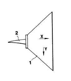
BRIEF DESCRIPTION OF THE DRAWINGS
Figs. lA and lB are a side elevational view and a front
view, respectively, showing a mold employed for molding the
diaphragm.
Fig. 2 is a chart showing sound pressure frequency
characteristics of a full-range speaker formed of the polyolefin
composition and a speaker formed of ordinary polypropylene.
DETAILED DESCRIPTION OF THE INVENTION
It is known that, if the molecular chain of an organic high
polymer material is oriented in one direction, physical
properties of the material, such as modulus of elasticity or
tensile strength, may be improved significantly. As an example,
if polyethylene as a general-purpose high polymer material is
oriented to a higher degree, its theoretical modulus of
elasticity may be computed to be 250 GPa. As a matter of fact,
fibers having the modulus of elasticity of 200 GPa have been
produced on the laboratory level by a technique such as gel
elongation, while fibers having the modulus of elasticity in the
order of 90 to 100 GPa have been presented to the market.
Therefore, molecular chain orientation is an effective means for
improving the modulus of elasticity to meet the demand raised in
connection with a speaker diaphragm.
According to the present invention, a polyolefin composition
obtained by multi-stage polymerization of an ultra high molecular
weight polyolefin with a high melting viscosity and a low to high
2 ~
molecular weight polyolefin with a low melting viscosity is used
and the molecular chains of the ultra high molecular weight
polyolefin are oriented radially by means of injection molding
taking advantage of the differential fluidity between these two
components to improve the modulus of elasticity of the
composition.
It is critical that the two components of ~he polyolefin
composition having markedly different melting viscosity be mixed
uniformly together. If the polyolefin composition obtained by
multi-stage polymerization is melted and fluidized, the low
viscosity component acts as the inner lubricant to stretch the
high viscosity component, that is the ultra high molecular weight
polyolefin, in the direction of increasing fluidization, to
realize extensive orientation of the molecular chains.
., ,
; Conversely, if only the ultra high molecular weight
polyolefin and low to high molecular weight polyolefin are simply
mixed together and the resulting mixture is injection molded, the
high viscosity component is not dispersed minutely, although some
extent of orientation is realized, and hence the molded product
'~is subject to, for example, laminar exfoliation, such that
optimum characteristics are not obtained.
It is critical in the present invention that the olefinic
composition, employed as the molding material, be a homopolymer
or a copolymer of ~-olefins, such as ethylene, propylene, 1-
butene, 1-pentene, 1-hexene, 1-octene, 1-decene, 1-dodecene, 4-
:
;
.
:: .
methyl-1-pentene or 3-methyl-1-pentene, and that the two
components exhibiting markedly different melting viscosities be
mixed uniformly together.
That is, the composition is a homogeneous mixture of an
ultra high molecular weight polyolefin having a limiting
viscosity of 10 to 40 d~/g and a low to high molecular weight
polyolefin having a limiting viscosity of 0.1 to 5 d~/g.
Such olefin compound has been known per se and the method
for producing the same is shown for example in the Japanese
Patent Publication No. JP.A01-144533(1989). More specifically,
it may be produced by a method of multi-stage polymerization of
an olefin or olefins in the presence of a catalyst consisting
essentially of a certain high-activity solid titanium catalyst
component and an organoaluminium compound catalyst.
The multi-stage polymerization is performed by carrying out
the process of olefin polymerization in plural stages in the
presence of a Zegler type catalyst constituted by a high active
titanium catalyst component (a) consisting essentially of
magnesium, titanium and halogens and an organoaluminium component
(b). The ultra high molecular weight polyolefin having a
limiting viscosity of 10 to 40 d~/g is produced in at least one
polymerization process and the olefin is polymerized in another
polymerization process in the presence of hydrogen to produce the
low to high molecular weight polyolefin having a limiting
viscosity of 0.1 to 5 d~/g.
2 ~
Hence, a multi-stage polymerization apparatus comprised of
at least two series connected polymerization tanks is used for
polymerization, with the number of polymerization being 2 to n,
n being an optional integer. Alternatively, the multi-stage
polymerization may be carried out by batch polymerization using
a single polymerization tank.
In the above mentioned multi-stage polymerization, the
polymerization reaction of producing the ultra-high molecular
weight polyolefin or of producing the low to high molecular
weight polyolefin may be practiced by a gas-phase polymerization
or a liquid-phase polymerization. In either case, the
polymerization reaction of producing the polyolefin is carried
out in the presence of an inert medium, such as aliphatic,
alicyclic, aromatic or halogenated hydrocarbons, as the occasion
may require. For producing the ultra high molecular weight
polyolefin durlng the polymerization process, the polymerization
reaction is preferably carried out in the absence of hydrogen.
On the other hand, in the polymerization process other than the
process of producing the ultra-high molecular weight polyolefin
as described above, the polymerization reaction for the remaining
olefins is carried out in the presence of hydrogen.
the so-produced polyolefin composition is used as the
molding material and injection molded under customary injection
molding conditions to produce a diaphragm. It is preferred that
the molding material be injected at the center of the mold to
permit the melted molding material to flow radially within the
mold.
The molding material, consisting essentially of the above
mentioned polyolefin composition, may additionally contain mica, r
glass fibers or the like fillers. From the aspect to fluidity,
the filler content is preferably about 40 wt. % at the maximum.
The present invention will be explained in detail with
reference to concrete experimental results.
ExamPle 1
Composition
A polyethylene composition was prepared by a two-stage
polymerization of polymerizing ethylene in two stages in the
presence of a catalyst consisting essentially of a high-active
solid titanium component and an organoaluminium compound
component.
limiting viscosity (Decalin, measured at 135~C)
ultra-high molecular weight
polyethylene, 30 d~/g
low to molecular weight
polyethylene, 0.7 dQ/g
composition, 8.1 d~/g
amounts of the components
ultra-high molecular weight
polyethylene, 25 wt.%
low-to-high molecular-weight
polyethylene, 75 wt.%
In~iection Moldinq
Using an injection molding apparatus (IS-55 mfd. by Toshiba
Kikai Co. Ltd.), the above mentioned polyethylene composition was
injection molded into a conical mold 1 shown in Fig. 1A and lB
by means of a central nozzle 2 to produce a 16 cm cone-shaped
full-range speaker under the following injection molding
conditions:
Cylinder Temperature; 200 to 270~C
Injection Pressure; 1st/2nd=1800/800
Mold Temperature; 32~C(water cooling).
A portion of the produced molded product (Example 1) was cut
out and its physical properties such as modulus of elasticity and
internal losses were measured by the vibration reed method to
appraise the properties as the speaker diaphragm. Measurement
was performed in the X-direction in Figs. lA and 1B, that is the
radial direction with the nozzle of the injection molding as the
center, and in the Y-direction, that is the direction orthogonal
to the X-direction. The items of appraisal were the internal
losses tan o, Young's modulus ~, densi-ty and the speed of
propagation of the longitudinal waves C. For comparison, similar
appraisal was made of the molded products formed of usual
polypropylene ~Comparative Example). The results are shown in
Table 1.
Table 1
direction tan ~ ~ 3 C
(GPa) (kg/m ) (m/sec)
Ex. 1 X 0.041 7.78 971 2831
Y 0.053 2.21 971 1~10
Comp. Ex X 0.065 2.29 901 1594
Y 0.071 1.89 901 1448
It may be seen from Example 1 that the molecular chains are
oriented in the direction of driving the speaker diaphragm, that
is, in the X-direction, with resulting improved modulus of
elasticity.
Conversely, in the Comparative Example employing usual
polypropylene, although some orientation occurred, the effect
of orientation could hardly be noticed.
It is noted that the properties of the non-oriented
polyethylene composition employed in Example 1 were substantially
similar to those of Example 1 as measured in the ~-direction.
The sound pressure frequency characteristics of the produced
speaker diaphragm were measured for comparison between the
Example and the Comparative Example. The results are shown in
Fig. 2.
It is seen from these results that the playback frequency
region of the speaker diaphragm formed of the above described
polyethylene composition has been enlarged, which is thought to
be attributable to the improved modulus of elasticity brought
about by orientation. It is also seen from Example 1 that smooth
,
:, :
frequency characteristics in the high frequency region have been
achieved despite increased modulus of elasticity, thus indicating
that proper internal losses are maintained.
Example 2
In the present Example, an appraisal was made of the
composition admixed with the filter.
The polyethylene composition was prepared in the same way
as in Example 1 and admixed with 15 wt.% of chopped strands of
carbon fibers each 6 mm in length. The resulting mixture was
injection molded in the same way as in Example 1 A portion
thereof was cut and its physical properties were measured by the
vibration reed method in the same way as in Example 1 to appraise
its properties as the speaker diaphragm. The results are shown
in Table 2.
Table 2
direction tan ~ ~ C
(GPa) (kg/m3) (m/sec)
Ex. 2 X 0.021 13.43 1054 3570
Y 0.032 3.45 1054 1810
It is seen from these results that, in addition to the
effects orientation, noticed in Example 1, the carbon fibers are
also oriented, with the result that the modulus of elasticity in
the X-direction may be improved significantly.